Italeri 1/72 Ca-311
| KIT #: | 113 |
| PRICE: | $20.00 AUD |
| DECALS: | Four options |
| REVIEWER: | Alwin Broekelmann |
| NOTES: |
| HISTORY |
In order to replace the outdated
reconnaissance aircraft the Ro. 37, the Italian Air Ministry decided in 1939 to
choose a new reconnaissance plane with more advanced features. This aircraft was
designed to also qualify as a light tactical bomber and fighter. Further
specifications called for a crew of 3, twin engines and a speed of not less than
400kmh (250 mph). CAPRONI, the builder partly fulfilled these requirements first
with the 310 and latter with the CA 311. This plane was streamlined with a front
glass section to give the crew maximum visibility. The defensive armament was
quite basic and insufficient included one 7.7mm machine gun placed in the
ventral position, one 7.7mm machine gun in a revolving turret just behind the
cockpit which was to be used for rear and side protection and one 7.7mm machine
gun was placed in the wing mounted on the left side close to the cockpit wall
for low level strafing. It had a bomb load of 400kg (880ld) and had basically
well conceived aerodynamic features and was equipped with Piaggio 470 hp
engines. These proved to be only powerful enough for the prototypes with out
armament and 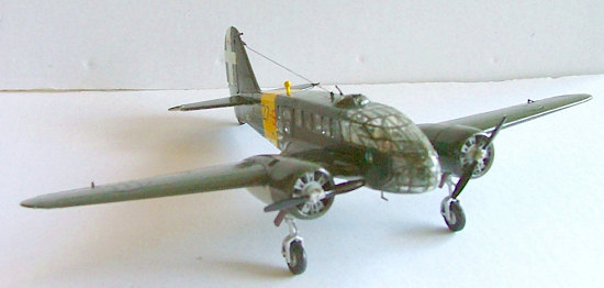 bomb load, but
caused problems for mass-produced fully equipped units, which included armament.
Further failures resulted from the glass structure of the cockpit; these were
eliminated by redesigning the cockpit profile. Similar changes were made to the
two related aircraft the CA 313 and 314. The plane first saw service in 1940 in
the African campaign, where they were assigned to the 129th Squadron.
In spite of the inadequate performance of the engines and insufficient armament
they distinguished themselves in numerous actions, in Africa, the Balkans and in
Russia, thanks to the ability of their brave crews. Having taken part on many
fronts, the CA 311 reached the end of the war still in action with Flying
Schools in various areas.
bomb load, but
caused problems for mass-produced fully equipped units, which included armament.
Further failures resulted from the glass structure of the cockpit; these were
eliminated by redesigning the cockpit profile. Similar changes were made to the
two related aircraft the CA 313 and 314. The plane first saw service in 1940 in
the African campaign, where they were assigned to the 129th Squadron.
In spite of the inadequate performance of the engines and insufficient armament
they distinguished themselves in numerous actions, in Africa, the Balkans and in
Russia, thanks to the ability of their brave crews. Having taken part on many
fronts, the CA 311 reached the end of the war still in action with Flying
Schools in various areas.
Tech Data:
Wingspan: 16.20m
Length: 11.74m
Net weight: 3500kgs
Max weight: 4860kgs
Max speed: 350kmh
Range: 1600km
Max altitude: 6500m
Crew: 3
Armaments: 3-6 7.7mm machine guns
Bomb load: 400kg
Engines 2 Piaggio P VII C. 35 400/470hp
| THE KIT |
3 Sprue's 2 plastic parts and one with
clear parts these include 2 upper cockpit options, a set of basic decals. The
instructions are typical of Italaerei in this period, an A5 sheet folded into 3
pages, info on the aircraft on front page in 3 languages, page 2 is layout of
parts and a 4 description of the aircraft in another language. Page 3 & 4
contain a 7 step pictorial guide to assembling the kit
 and the back 2 pages is your
painting guide showing 4 different schemes.
and the back 2 pages is your
painting guide showing 4 different schemes.
(Alwin could have also mentioned that one has the option
of building either the stepped or full nose version, that there are ejector pin
marks on nearly all the parts, and that the transparencies are somewhat thick.
The aircraft is considered a 'medium' bomber [according to the box] and comes
with a full bomb load. A rather complete cockpit section with seats, instrument
panel and control columns is includes with the rudder pedals molded to the
floor. Though one can see into the interior through all the transparencies, it
is relatively sparsely detailed. This is an old Italeri kit from the late
1960s/early 1970s and the moldings show it. Another indication of its age is
that it comes with crew figures and a display stand [at least my copy does].
Each of the two nose options has two markings options; one for a solid green
over grey plane and for a sand with brown and green mottles. Ed.)
| CONSTRUCTION |
Once I had made the decision on which aircraft to build, I started as per the
instruction sheet by putting together the bomb load, which consists of 8 bombs,
their holding brackets, the load rails and base plate. This was a relatively
simple task and was done quickly. Next came the cockpit section after painting
the pilots I decided not to use them and put them in my spares box. Then moved
onto the floor plate, seats, control yoke, instrument bar as this is not a dash
but an upright bar in the centre of the cockpit then a rail leans over to the
right side in front of the pilots position. Then to the rear of the pilots seat
were placed what appears to be a nav table and a radio set. I then made up the
top turret this was a truly fiddly task and took quite a bit of time and
patience, next was the rear ventral gunners tub a simple task and done in short
time. I then moved onto placing the side glass in no drama here, next mating the
2 halves with all their components. They went together nicely with no gaps
anywhere they shouldn't be, attach rudder, tail wheel, top radio bea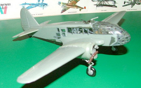 con,
ventral gunners tub and ventral glass. The latter 2 proving to be tricky, as I
was not using the gunner so the tub is in the raised position and the glass
section needed some fine trimming to fit correctly. Fit the nose glass and
chosen upper cockpit glass takes a bit to align correctly and a trim was need
once the glue had set.
con,
ventral gunners tub and ventral glass. The latter 2 proving to be tricky, as I
was not using the gunner so the tub is in the raised position and the glass
section needed some fine trimming to fit correctly. Fit the nose glass and
chosen upper cockpit glass takes a bit to align correctly and a trim was need
once the glue had set.
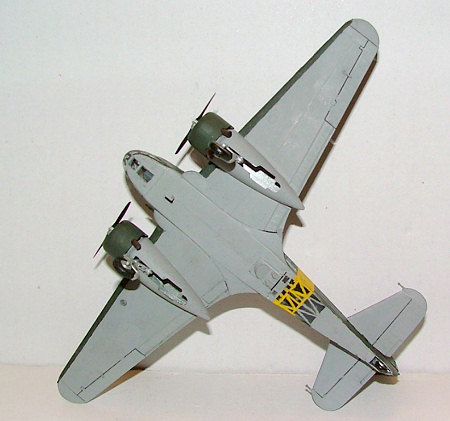
While all that was left to set I moved onto the next stage, which was to assemble the wings and ailerons, which I set at level. Then the tail plane and elevators, these I set to droop as is common with aircraft on the ground. Then fit these to the fuselage, no problems here though I thought there was a gap, but on checking 3 plan views and a couple pics found this was not a gap but a design feature. Now to build the engine pods straight forward enough just follow the pictures to the letter right, no as they show only placing the landing gear minus wheels. Then 2 stages latter place the landing gear lock brace if you are having gear down, but you need to fit this at the same time as the leg or you have to cut the locating pin off one side to get it into place. Not a great deal of trouble with the engines as they are quite nicely molded and are clear of plastic between the pots. Then fitting the pods [nacelles] to the wing at this point I noticed the fact that the top section of the pod that I glued together as I though I broke then get them off the sprue was in fact meant to be like that, so that it fits over the wing. Never mind cut and clean the test fit again and they actually go into the correct spot without any undue force. But test, test and test again before you put any glue as there is apparently a knack to get them into place, without getting glue all over the wing, I never found it and had to clean up once the glue dried. Glue your landing gear springers, slide your wheel into the leg, fit mudguards a little fiddly then chin pitot tube and you are ready to paint.
| COLORS & MARKINGS |
 Painting:
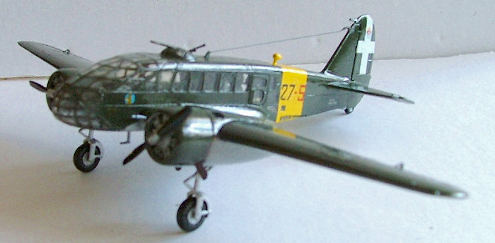
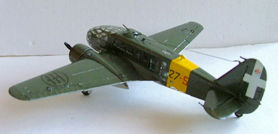
After the last Italian jobs a Fiat Cr-42 and SM- 79 with mottle pattern, I opted for a simple two colour dark green upper and sky grey belly. After painting I fitted the antenna wire using black sewing thread.
Decals:
These went on easily after I treated them with tamiya x-20 clear coat as the were extremely brittle and the test one’s that I used broke up badly. So remember to clear coat for safety if in doubt.
| CONCLUSIONS |
Over all a pleasant kit to work on, needs a bit of experience so would not recommend this one for the beginner. Has come up very nicely and is a good addition to my rare and not so well known bird collection.
(As a note to Alwin on his photos. You need to back up or something as all your images [except the one to the right] were out of focus to one extent or another. Basically the backgrounds were in focus, but the subject was not. Ed)
| REFERENCES |
Bill Gunston’s Combat aircraft of WW2
Plan 3 views. www.richard.ferriere.free.fr/3vues/3vues.html
Virtual Air Museum. www.avia.russian.ee/index2.html
Alwin Broekelmann
November 2007
Copyright ModelingMadness.com
If you would like your product reviewed fairly and fairly quickly, please contact the editor or see other details in the Note to Contributors.