| KIT #: | 04101 |
| PRICE: | $10.00 in 1988 |
| DECALS: | Two options |
| REVIEWER: | Stephen Young |
| NOTES: | Kit is generally available on Ebay although buyer beware regarding inflated minimum bid prices. A newer Glencoe release is available as kit #5125 and adds decals for a U.S. Coast Guard JF-2.True Details resin seat; EZ Line fine and heavy for rigging |
| HISTORY |
When Leroy Grumman formed the Grumman Aircraft Engineering Company in 1929 the
business relied on repairing and rebuilding aircraft as well as developed a
series of floats with retractable landing gear. Proposed to the U.S. Navy in
1931 as a amphibian utility aircraft, the XJF-1 Duck prototype was ordered in
1932. After evaluation and redesign the JF-1 was accepted for production in
small numbers as a utility aircraft to support fleet aircraft carriers. The next
version was the JF-2 contracted by the U.S. Coast Guard for search, rescue and
patrol duties and delivery began in 1934. In 1936 further improvement resulted
in the J2F-1 Duck that featured a lengthened main float to improve water
performance and
 equipment for target towing, smoke generation, photography, and
medical evacuation. Twenty-eight were delivered to the Navy.
equipment for target towing, smoke generation, photography, and
medical evacuation. Twenty-eight were delivered to the Navy.
These aircraft were followed by the J2F-2 model featuring a more powerful 790 hp Pratt and Whitney R-1820-30 engine; thirty were delivered to the U.S. Navy and the U.S. Marines. Of the Marine aircraft nine were modified as J2F-2As in 1939 to equip Marine Scouting Squadron 3 (VMS-3) for Neutrality Patrol duty in the Caribbean. Further product improvements resulted in the J2F-3, J2F-4, J2F-5 and finally the J2F-6. Due to war time combat aircraft production priority for Grumman, Duck production was sub-contracted to Columbia Aircraft Corporation in 1941. The J2F-6 was the most numerous version manufactured with 330 being built and the last delivered by the Columbia Aircraft Corporation in 1945. Through out its career the Duck served in a general utility and light transport duties but also performed missions including mapping, scout/observation, anti-submarine patrol, air-sea rescue, photographic survey, reconnaissance and target tug duty with small numbers of aircraft assigned to various squadrons in the US Navy, the US Marine Corps, the US Coast Guard, the US Air Force and several foreign navies. It is probably most recognized for its use in the 1971 movie “Murphy’s War” that featured a J2F-6 Duck flown by Murphy in his obsession to destroy the Kriegsmarine submarine that sank his ship. Several examples survive today in the United States.
| THE KIT |
Initially released in 1958 by ITC Model Craft, Glencoe Models
re-released the kit as J2F-2 Duck, kit number 04101, in 1988, in 2006 as kit
number 4101 and currently as kit number 5125. Although listed as “Approximately
1/48th
scale” the model is actually 1/52nd
scale per the kit instruction sheet. Molding in light gray plastic consisting of
fifty-six parts with a single piece clear canopy, the quality of the kit is
great for 1958 technology (I’m old enough to know the difference!) but when
measured by the best of today’s technology will shock the modeling senses. The
fuselage has prominent rivets and basic details are soft or even completely
incorrect. The cockpit interior consists of a floor and two seats that resemble
bucket seats from my 1969 Volkswagen Beetle. Two half figures are pr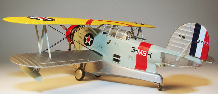 ovided as
crew and they are much too large for the scale. I have no idea if the overall
dimensions are correct but comparison to photos of a J2F-2 show additional
missing features such as the air intakes above and below the engine cowling, a
simplified and inauthentic landing gear and rear tail wheel, and no interior
under the cockpit. Under wing rocket launchers and integrally molded in rockets
are also included although these were never used on any Duck. Later versions did
have the capability for under wing racks able to carry bombs and even 325 pound
depth charges but these are not provided. The included Scale-Master decals
provide markings for three aircraft; a U.S. Marine Corp VMS-3 Duck based in the
United States Virgin Islands, a U.S. Navy plane of Utility Squadron 1 based at
Pearl Harbor, Territory of Hawaii, and an Argentine Navy aircraft. The
instructions for assembly are very basic although the markings and decal
placement diagrams are clear.
ovided as
crew and they are much too large for the scale. I have no idea if the overall
dimensions are correct but comparison to photos of a J2F-2 show additional
missing features such as the air intakes above and below the engine cowling, a
simplified and inauthentic landing gear and rear tail wheel, and no interior
under the cockpit. Under wing rocket launchers and integrally molded in rockets
are also included although these were never used on any Duck. Later versions did
have the capability for under wing racks able to carry bombs and even 325 pound
depth charges but these are not provided. The included Scale-Master decals
provide markings for three aircraft; a U.S. Marine Corp VMS-3 Duck based in the
United States Virgin Islands, a U.S. Navy plane of Utility Squadron 1 based at
Pearl Harbor, Territory of Hawaii, and an Argentine Navy aircraft. The
instructions for assembly are very basic although the markings and decal
placement diagrams are clear.
| CONSTRUCTION |
Probably like many modelers dealing with alignment of a second wing and
rigging has always seemed daunting. In fact I had never before build a biplane
model with this and a few other biplane kits languishing for years in my
collection. Having jumped on the Airfix wagon by purchasing the company’s
excellent new Supermarine Walrus it seemed like a good idea to finally develop a
technique to meet the alignment and rigging challenges before taking a project
with more financial and emotional investment. What better way than to retrieve
an old, low value kit from the collection and try things out. Relying on Steve
Ginter’s excellent Naval Fighters Number Eighty-four Grumman JF/J2F Duck for
reference it became clear that built truly out of the box the model really would
result in a flash back to the 1950’s era of modeling so I decided to make some
changes to make the finished model look a little more in tune with today but
still limit the time investment. After washing the parts in warm water and
dishwashing detergent to remove any mold release agents some test fitting was
done to assist in construction planning. The kit seats were discarded in favor
of a 1/48 resin and donor kit seats from the spares box; one was a Squadron True
Details P-47 seat and the other came from an unknown 1/48th
kit. Although not accurate for any Duck they look far better than the kit seats
once painted, highlight washed and installed with a closed canopy model. I
thought about adding two 1/48th
scale crew members but there was no way to make any of my saved spare pilots fit
in the small space with the replacement seats. There is no hull interior below
the cockpit floor despite the clear windows but I decided to leave that area
alone. To prevent a direct view into the hull/fuselage through the wheel wells
they were blanked off using pieces of 0.020 sheet styrene trimmed to fit and
cemented in place with liquid cement. The entire fuselage interior was airbrush
painted Testors Model Master Aluminum as was the cockpit floor. Based on black
and white photos of pre-war Ducks it appears the interior was either natural
metal or painted aluminum color except for the instrument panels. The inaccurate
and basic pilot’s control panel was painted flat black with silver dials. Since
no control st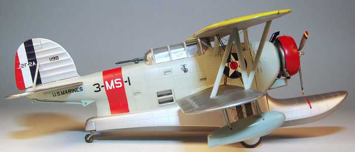 ick is included in the kit one was fabricated out of carved
stretched sprue, painted Testors Silver, and installed. The hull windows were
attached from the inside using Tamiya Extra Thin liquid cement (a superb fast
setting liquid plastic solvent cement) and the fit is good and secure. The
landing gear needs to be installed before the fuselage halves are joined and are
designed to raise and lower although when raised the fit, with wheels attached,
leaves much to be desired. The legs and links bear little resemblance to the
real aircraft but I decided not to make any changes. The legs were airbrushed
with Testors MM Aluminum and then assembled per the kit instructions.
ick is included in the kit one was fabricated out of carved
stretched sprue, painted Testors Silver, and installed. The hull windows were
attached from the inside using Tamiya Extra Thin liquid cement (a superb fast
setting liquid plastic solvent cement) and the fit is good and secure. The
landing gear needs to be installed before the fuselage halves are joined and are
designed to raise and lower although when raised the fit, with wheels attached,
leaves much to be desired. The legs and links bear little resemblance to the
real aircraft but I decided not to make any changes. The legs were airbrushed
with Testors MM Aluminum and then assembled per the kit instructions.
The
fuselage halves assembled well using liquid cement after attaching the cockpit
floor. Fit was good and only a minute amount of Bondo red auto body putty
thinned with lacquer thinner and a small amount of Testors liquid cement was
needed on a couple of areas of the seam line. (Incidentally in my experience
thinning the Bondo with lacquer thinner alone does not provide enough adhesion
to bare styrene plastic but this seems to be corrected by adding about 10%
Testors liquid cement to the mix. However, one must be careful to avoid over
application due to the risk of dissolving plastic.) Sanding the seam naturally
removed some of the rivet detail so after the filling and sanding was completed
the rivet detail was restored using the R&B Productions Rivet-R Mini tool
(#RB-T010) that was being used for the first time. The R&B tool is very nice and
comes with four different wheels with varying rivet spacing that is clamped into
a common hobby knife holder (not included). The entire engraving wheel is
visible while it is being used so very precise placement of the engraving is
possible with care. One wheel matched the original kit rivet spacing exactly and
the engraved rivets look quite good when the surface is painted. Once the
fuselage was complete the next step was the wings. Both lower wing halves and
the top wing halves were assembled using liquid cement. The lower wings surface
has four holes per side to receive the rocket launchers that I did not intend to
use so the holes were filled with stretched sprue and Bondo putty and sanded
smooth. After finish sanding of the peripheral join seam the bottom wings were
ready for attachment to the fuselage. On a biplane accurate and symmetrical
attachment is essential since the top wing must align with the bottom. On the
Duck the bottom wing has 3 degrees of dihedral while the top wing has 0 degrees
of dihedral. Although the wing tab is slightly angled to provide the dihedral
the corresponding fuselage slot fit is much too loose to rely upon a accurate
assembly. To solve the problem and later assist in the top wing assembly a jig
was made using inexpensive Styrofoam construction board readily available at any
office supply, craft store or Walmart store. Styrofoam construction board
consists of two heavy, smooth paper sheets laminated to a core sheet of
Styrofoam and is precisely 0.25 inches thick. It is very easily and accurately
cut with a box cutter with a new, sharp blade against a steel straight edge. The
jig components were assembled with the necessary 3 degrees of dihedral on the
jig to support the lower wings. Regular white PVA glue was used to assemble the
jig and lengths of tooth pick were strategically placed and glued to allow the
model parts to be held in place using small rubber bands. The fuselage was
aligned in the jig and held in place by the rubber bands and the lower wings
were then glued in place with liquid cement. Following this the horizontal
stabilizer assembly was cemented in place although a minor amount of trimmin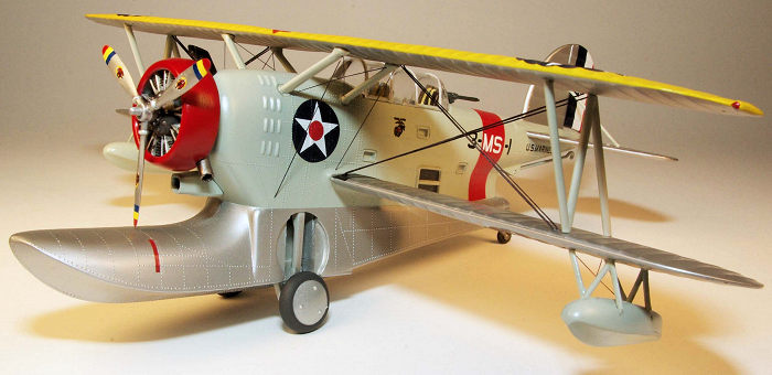 g of
the mating surface was needed for accurate alignment. The rudder was then
attached. After the assembly was cured the fuselage/wing/stabilizer was removed
for masking and painting. It and the upper wing would need to be finish painted
before assembly since it would be impossible to accomplish once both wings were
assembled. In addition the small components were assembled and painted including
the engine, wheels, cowl ring, and struts. The upper air intake above the cowl
ring and the lower air intake below the cowl ring were present on the J2F-2 but
omitted from the model. The upper intake was carved from a section of left over
sprue and the lower intake was made from the parts from the spares box. A small
section of 1/64th brass rod was
glued with CA into each to provide reinforcement for the attachment to the
fuselage. The exhaust ring was used although it is not accurately represented;
in the real aircraft the lower part of each exhaust is slightly curved. The ends
were drilled out for appearance.
g of
the mating surface was needed for accurate alignment. The rudder was then
attached. After the assembly was cured the fuselage/wing/stabilizer was removed
for masking and painting. It and the upper wing would need to be finish painted
before assembly since it would be impossible to accomplish once both wings were
assembled. In addition the small components were assembled and painted including
the engine, wheels, cowl ring, and struts. The upper air intake above the cowl
ring and the lower air intake below the cowl ring were present on the J2F-2 but
omitted from the model. The upper intake was carved from a section of left over
sprue and the lower intake was made from the parts from the spares box. A small
section of 1/64th brass rod was
glued with CA into each to provide reinforcement for the attachment to the
fuselage. The exhaust ring was used although it is not accurately represented;
in the real aircraft the lower part of each exhaust is slightly curved. The ends
were drilled out for appearance.
Once the finish painting and decal application
was done including the satin clear coat the model was replaced in the jig and
the interplane struts (the ones toward the wing tips) carefully test fitted to
the lower wings and the upper wings. The cabane struts (attaching the upper wing
to the fuselage) have attachment pins where they meet the wings while the
fuselage end inserts into a slot within an excessively large hole in the upper
fuselage. The angle of the fairing on the wing end was too acute for each of the
cabane struts so some trimming and filing was performed to improve the fit
although it still ended up imperfect. Any resultant gaps were filled with
Testors Clear Parts cement then touch up painted with MM Aircraft Gray enamel.
The major challenge was coming up and that was the rigging. The Duck rigging was
actually termed “tie rods” by Grumman. There are eight long, flattened rods
running span wise; four to each side and in addition smaller tie rods between
the cabane struts on each side and connecting the upper wing to two
 points on
both the right and left sides of the forward fuselage. In addition there are two
tie rods connecting the inner struts for each lower wing float. The span wise
tie rods compared to the other tie rods have a flattened cross section that is
readily apparent on photos. After doing a fair amount of internet and YouTube
research on the many ways to rig a biplane model I decided to use EZ Line and
obtained both the fine and the heavy version. The heavy EZ line is flattened so
it was the best match to the span wise tie rods whereas the fine would be good
for the remainder. I decided to drill blind placement holes in the struts before
assembling the wings using a #77 micro bit and pin vise. One has to be careful
to match the placement of the holes with the direction of the rigging needed.
Also care must be taken to avoid twisting the EZ line representing the span wise
tie rods when attached. Once this was done the span wise rigging was glued into
the upper wing before the wing was attached to the lower wing. EZ line makes
this part simple since it is very elastic. Just cut a piece an inch longer than
the final finished distance and glue it by placing a very small and precise drop
of liquid CA in the locating hole. Holding the piece of EZ line with a fine
tweezers/forceps insert the end into the hole with the CA glue then while
holding it in place touch a tiny amount of CA accelerator to the joint with a
piece of stretched sprue. The EZ line will be instantly glued in place. This
resulted in a total of eight lengths of heavy EZ line being glued to the bottom
of the top wing. Once this was done, with the model aligned in the jig, the interplane struts were aligned then glued in place with CA. Once these had
cured, the upper wing was inserted onto the upper ends of the interplane struts,
alignment verified and held in place using small rubber bands, and these were
then glued with CA. After allowing several hours for the CA to set the cabane
struts were installed by also gluing with CA. As noted above there are somewhat
large holes in the fuselage where the cabane struts insert so after the glue had
set these were filled with multiple careful applications of Testors Clear Parts
cement. Once filled and dry the cement was over painted by hand with Aircraft
Gray. The next step was completing the rigging and this was accomplished by
cutting each length of rigging about 1 cm short of the final length then
stretching it to the correct hole with the CA glue applied. Once the CA
accelerator is touched to the join the line is glued ins
points on
both the right and left sides of the forward fuselage. In addition there are two
tie rods connecting the inner struts for each lower wing float. The span wise
tie rods compared to the other tie rods have a flattened cross section that is
readily apparent on photos. After doing a fair amount of internet and YouTube
research on the many ways to rig a biplane model I decided to use EZ Line and
obtained both the fine and the heavy version. The heavy EZ line is flattened so
it was the best match to the span wise tie rods whereas the fine would be good
for the remainder. I decided to drill blind placement holes in the struts before
assembling the wings using a #77 micro bit and pin vise. One has to be careful
to match the placement of the holes with the direction of the rigging needed.
Also care must be taken to avoid twisting the EZ line representing the span wise
tie rods when attached. Once this was done the span wise rigging was glued into
the upper wing before the wing was attached to the lower wing. EZ line makes
this part simple since it is very elastic. Just cut a piece an inch longer than
the final finished distance and glue it by placing a very small and precise drop
of liquid CA in the locating hole. Holding the piece of EZ line with a fine
tweezers/forceps insert the end into the hole with the CA glue then while
holding it in place touch a tiny amount of CA accelerator to the joint with a
piece of stretched sprue. The EZ line will be instantly glued in place. This
resulted in a total of eight lengths of heavy EZ line being glued to the bottom
of the top wing. Once this was done, with the model aligned in the jig, the interplane struts were aligned then glued in place with CA. Once these had
cured, the upper wing was inserted onto the upper ends of the interplane struts,
alignment verified and held in place using small rubber bands, and these were
then glued with CA. After allowing several hours for the CA to set the cabane
struts were installed by also gluing with CA. As noted above there are somewhat
large holes in the fuselage where the cabane struts insert so after the glue had
set these were filled with multiple careful applications of Testors Clear Parts
cement. Once filled and dry the cement was over painted by hand with Aircraft
Gray. The next step was completing the rigging and this was accomplished by
cutting each length of rigging about 1 cm short of the final length then
stretching it to the correct hole with the CA glue applied. Once the CA
accelerator is touched to the join the line is glued ins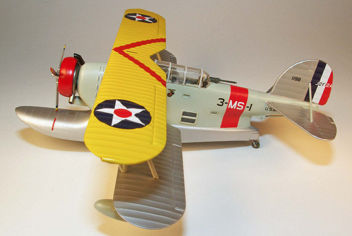 tantly. The process is
tedious and for me requires magnifying loupes to accomplish but really is not
very difficult. Much of this was accomplished with the model held in the jig
which simplified handling although some of the rigging was done with the model
resting on the egg crate foam pads that I always use to greatly simplify the
handling during construction at all phases. After the rigging was finished the
rigging insertion points were touch up airbrushed with Testors Dullcote/Glosscote
25%/75% to eliminate the shine of the CA glue residue. Final assembly then
proceeded with adding the intakes, engine, outrigger floats and their struts and
rigging and other small parts. Attachment of the propeller was reworked to more
closely match photographs since the kit plastic shaft provided looks atrocious.
The kit canopy was used and was pre-treated with a dip in Future. The framing
was hand painted with a 5-0 brush using Vallejo Acrylic paint.
tantly. The process is
tedious and for me requires magnifying loupes to accomplish but really is not
very difficult. Much of this was accomplished with the model held in the jig
which simplified handling although some of the rigging was done with the model
resting on the egg crate foam pads that I always use to greatly simplify the
handling during construction at all phases. After the rigging was finished the
rigging insertion points were touch up airbrushed with Testors Dullcote/Glosscote
25%/75% to eliminate the shine of the CA glue residue. Final assembly then
proceeded with adding the intakes, engine, outrigger floats and their struts and
rigging and other small parts. Attachment of the propeller was reworked to more
closely match photographs since the kit plastic shaft provided looks atrocious.
The kit canopy was used and was pre-treated with a dip in Future. The framing
was hand painted with a 5-0 brush using Vallejo Acrylic paint.
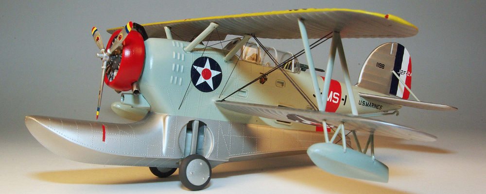
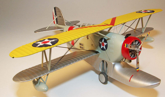
| COLORS & MARKINGS |
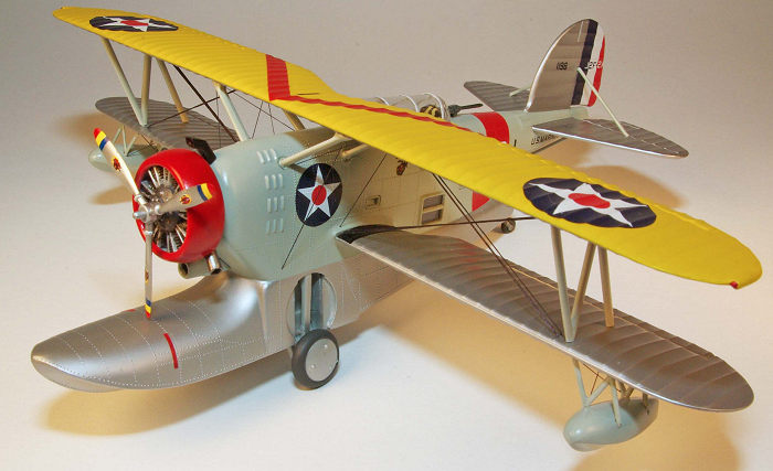
The interwar years includes that time in which many U.S. Navy aircraft were
painted in colorful schemes commonly called the “Golden Wings” era. Most of the
published photos from the 1930s are black and white and books are available
discussing in detail the lack of uniformity in finish application associated
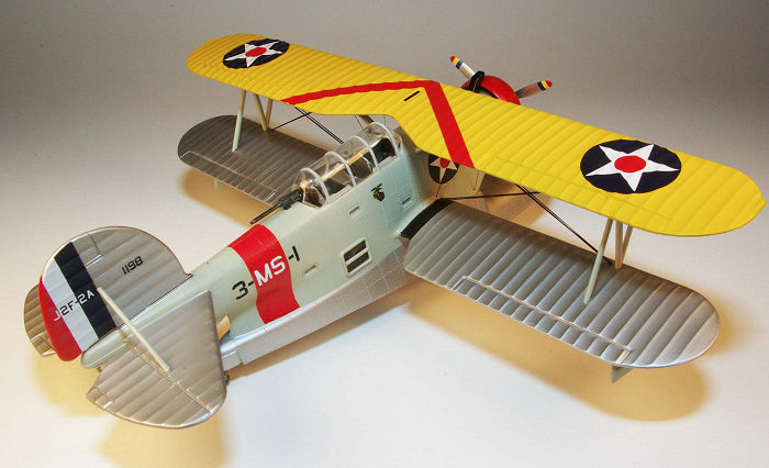
with a very thrifty Navy working with a very meager budget. The kit paint and
decal instructions for the VMS-3 Duck called for the commonly used finish of
Chrome Yellow for the upper wing and Aluminum for all other fabric surfaces with
Aircraft Gray for the metal surfaces. Searching the internet revealed a color
photograph attributed to National Geographic of VMS-3 aircraft in 1940 at St.
Thomas, VI, that shows the fuselage float appeared to be painted Aluminum or
perhaps unpainted and that the Chrome Yellow did not extend below the leading
edge of the top wing to the lower wing leading edge. The decals provided are for
the number one aircraft in a section of three therefore the entire cowl ring is
painted; the other two aircraft in a section would have the same color painted
on either the top or bottom half of the cowl ring. The major discrepancy in the
decal provided is the red stripe on the fuselage. The pictures available in the
Ginter’s book of VMS-3 aircraft do not show the band even though there is a
picture of aircraft 3-MS-1. I decided to use the decal provided since there was
no easy alternative. The fuselage windows were masked and then it was airbrushed
sparingly with Rustoleum gloss black enamel pre-shading followed by Testors
Model Master Aircraft Gray (FS16473). After several days of drying the fuselage
was masked and the float section, rudder, and stabilizer was airbrushed with
Testors Model Master Aluminum as was the entire bottom wing and the undersurface
of the top wing. After masking the undersurface the top of the top wing was
airbrushed with Testors RLM 04 Gelb that is a close match to Chrome Yellow
(FS13538). After several days of drying all surfaces were airbrushed with
Testors Glosscote to provide a base for the decals. This was my first experience
using Scale Master decals and they seem to have the milky white adhesive
typically found in late 1980s and 1990s era Monogram decals. Although thicker
than Superscale decals they went down pretty well even despite the raised rivets
and rib contour when treated with Wathers Solvaset although several applications
were needed along with carefully placed pin punctures to resolve bubbled are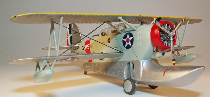 as
and minor slitting with a sharp scalpel to allow conformance to contours. In my
experience the Scale Master and Monogram decals work well enough provided 1)
warm water is used to wet the decals and then wash away most of the white
adhesive, 2) the surface receiving the decal is a variant of silver or natural
metal finish or white, and 3) a strong decal setting solution is available such
as Wather’s Solvaset. Without those three conditions the results will be
unsatisfactory for most discriminating modelers. Spare black decal film was used
for the wing walkways. Some minor decal fine brush applied paint touch up of
some decals was needed with matching colors. Once all the decals were applied
and adequate drying time allowed a final clear coat of Testors Glosscote/Dullcote
mixed 75%/25% was applied to give a slightly satin finish. After final assembly
the Aluminum float section of the fuselage was airbrushed with Testors Dullcote
thinned 20% with lacquer thinner. No weathering was done for two reasons; first,
all the period photos of VMS-3 show immaculately clean aircraft and second, my
skill in this area of modeling is atrocious.
as
and minor slitting with a sharp scalpel to allow conformance to contours. In my
experience the Scale Master and Monogram decals work well enough provided 1)
warm water is used to wet the decals and then wash away most of the white
adhesive, 2) the surface receiving the decal is a variant of silver or natural
metal finish or white, and 3) a strong decal setting solution is available such
as Wather’s Solvaset. Without those three conditions the results will be
unsatisfactory for most discriminating modelers. Spare black decal film was used
for the wing walkways. Some minor decal fine brush applied paint touch up of
some decals was needed with matching colors. Once all the decals were applied
and adequate drying time allowed a final clear coat of Testors Glosscote/Dullcote
mixed 75%/25% was applied to give a slightly satin finish. After final assembly
the Aluminum float section of the fuselage was airbrushed with Testors Dullcote
thinned 20% with lacquer thinner. No weathering was done for two reasons; first,
all the period photos of VMS-3 show immaculately clean aircraft and second, my
skill in this area of modeling is atrocious.
| CONCLUSIONS |
Once completed the model looks nice and is a colorful contrast in my
display case full of camouflaged WW II and modern aircraft. Certainly one needs
to understand that this model was created decades ago and the technology of the
time does not begin to approach the level of detail and precision possible
today. With some care and a little attention to construction and finishing
detail, especially with the added rigging, it builds reasonably well and looks
nice. Building experience is very helpful especially due to the alignment
requirements for the wings and, if desired, the rigging to simulate the tie
rods. If one omits the rigging the simplicity of the kit makes it very suitable
for the beginning modeler who wants to gain experience with assembling a
biplane. Just as important it provided an inexpensive way without a great deal
of financial or emotional attachment to gain valuable experience in rigging
aircraft. My observation is that there are
 several methods using various
materials to complete the task but having used the EZ Line I can attest to its
relative ease. The most significant advantage is the self-tensioning provided by
the elasticity of the EZ line. Tension and a taut appearance can be difficult to
achieve with most other rigid materials like sprue or wire unless a through hole
is used to allow the material to be pulled taut. Of course this then requires
the hole to be filled, the surface to be finished and then painted adding more
work. One product caution regarding the EZ line is that sunlight (ultraviolet
radiation) will cause deterioration of the line so sun light exposure is to be
avoided. Based on my experience the EZ line seems unaffected by enamel or full
strength lacquer thinner. In regards to the J2F series of aircraft, there are
two other kit options in 1/48th
scale; the 2016 issue Merit International kit #64805 and the out-of-production
Classic Airframes J2F-1, 2, 2A, 3, 4 kit #443 and Classic Airframes J2F-5, 6 kit
#445 and by most reviews each are good renditions of the Duck although the
Classic Airframes kit provides extensive resin and photo etch parts to
completely build up the full interior and all visible external details. Both
versions are higher priced and in the case of the Classic Airframes versions,
more difficult to acquire.
several methods using various
materials to complete the task but having used the EZ Line I can attest to its
relative ease. The most significant advantage is the self-tensioning provided by
the elasticity of the EZ line. Tension and a taut appearance can be difficult to
achieve with most other rigid materials like sprue or wire unless a through hole
is used to allow the material to be pulled taut. Of course this then requires
the hole to be filled, the surface to be finished and then painted adding more
work. One product caution regarding the EZ line is that sunlight (ultraviolet
radiation) will cause deterioration of the line so sun light exposure is to be
avoided. Based on my experience the EZ line seems unaffected by enamel or full
strength lacquer thinner. In regards to the J2F series of aircraft, there are
two other kit options in 1/48th
scale; the 2016 issue Merit International kit #64805 and the out-of-production
Classic Airframes J2F-1, 2, 2A, 3, 4 kit #443 and Classic Airframes J2F-5, 6 kit
#445 and by most reviews each are good renditions of the Duck although the
Classic Airframes kit provides extensive resin and photo etch parts to
completely build up the full interior and all visible external details. Both
versions are higher priced and in the case of the Classic Airframes versions,
more difficult to acquire.
| REFERENCES |
Naval Fighters Number 84 Grumman JF/J2F Duck, Steve Ginter, 2009
U.S. Navy Flying Boats and Amphibians in World War II, Al Adcock, Squadron Signal, 2008
The Official Monogram US Navy and Marine Corps Aircraft Color Guide, Vol. 1, 1911-1939, John Elliott, Monogram Aviation Publications, 1987
March 2018
Copyright ModelingMadness.com Thanks to
for the review kit. You can find this one at your favorite hobby shop
or on-line retailer. If you would like your product reviewed fairly and fairly quickly, please
contact
the editor or see other details in the
Note to
Contributors.
Back to the Main Page
Back to the Review
Index Page
Back to the Previews Index Page