Classic Airframes 1/48 J2F-2 Duck
| KIT #: | |
| PRICE: | |
| DECALS: | Five options |
| REVIEWER: | Michael Rohde |
| NOTES: |
| HISTORY |
In 1932 Grumman began to develop a new utility amphibian aircraft which would combine the better features of the successful Grumman FF-1 Navy fighter and the Loening OL, a amphibian utility aircraft which was in service with the US Navy( and the US Army) for about 10 years already. Later that year Grumman submitted its proposal for review by the US Navy. This resulted in the award of a contract for the supply of one XJF-1 prototype and this aircraft flew for the first time on May 4th 1933.
Flight testing found no serious problems, and an evaluation by the USN resulted in the initial production order for 27 JF-1’s, the first of these being delivered in late 1934. The JF-1’s were intended to fulfil a general utility role and the type replaced the aeging Loening OL-9 observation and general purpose aircraft in service with the USN, and it was not until 1936 that the JF-1’s began to reach VJ squadrons.
 The
Grumman JF-1’s performance by comparison with the Loening was quite
staggering indeed. Maximum speed, rate of climb and service ceiling all
increased by 40, 50 and 65 % respectively. The design featured significant
aerodynamic improvements. The single bay biplane wings were of equal span,
the basic structure was made of light alloy and fabric covered. Frise type
ailerons on both upper and lower wings provided good roll control.
The
Grumman JF-1’s performance by comparison with the Loening was quite
staggering indeed. Maximum speed, rate of climb and service ceiling all
increased by 40, 50 and 65 % respectively. The design featured significant
aerodynamic improvements. The single bay biplane wings were of equal span,
the basic structure was made of light alloy and fabric covered. Frise type
ailerons on both upper and lower wings provided good roll control.
The fuselage was a conventional stressed skin/light alloy structure with the large monocoque central float built in. The landing gear was attached to, and retracted into ,recesses in this float structure.Stabilizer floats were mounted beneath each lower wing. A crew of two or three could be carried in the tandem cockpits. The power plant of the prototype and the first batch of JF-1 production aircraft consisted of a 700 hp Pratt & Whitney R-1830 Twin Wasp radial engine.
The contract which followed was for 14 JF-2’s for the US Coast Guard, these having equipment changes and 750hp Wright R 1820 Cyclone radial engines. Four of these were subsequently transferred to the USN and five more were aquired under the designation JF-3.The basic design was such that there were few major changes in later production examples ( ie the JF-3 and 4’s) and nine JF-2’s operated by the US Marines were equipped with machine guns and carried under wing bomb racks.
The last version to be built was ordered in 1940 and comprised of 144 JF-2F-5’s which were to carry the official name ‘Duck’. Generally similar to previous utility models, these were powered by the 850 hp Wright R 1820-50 engine. Most ‘Ducks’ remained in service throughout WW 2 and operated both from carriers and land bases in a variety of roles including Anti submarine patrol, photo survey, reconnaissance, Air -Sea rescue and target towing.
| THE KIT |
 This is a multi media kit set consisting of 3 frames holding 73
light grey plastic parts and one frame with 4 clear parts. 24 resin parts
are provided. Panel lines and other details are recessed. Rivet lines are
missing and have to be engraved by hand for enhancement. Dry fitting parts
before assembly is recommended.
This is a multi media kit set consisting of 3 frames holding 73
light grey plastic parts and one frame with 4 clear parts. 24 resin parts
are provided. Panel lines and other details are recessed. Rivet lines are
missing and have to be engraved by hand for enhancement. Dry fitting parts
before assembly is recommended.
Decal options are:
VMS-3 Bourne Field Virgin Islands 1940
NAS Pensacola 1938
A selection of additional markings are provided. These are:
Fleet Airbase Canal Zone US Navy
Alameda US Navy
NAS Pensacola US Navy.
The instructions are easy to follow and are arranged into 9 steps. A rigging diagram is included.
| CONSTRUCTION |
I started with a close inspection of all the plastic parts, removed them from their respective frames and arranged the part into sub assembly groups according to the instructions. All pieces had to be cleaned up ( removing flash and mould seams ) before commencing.
Step 1: The cockpit. All the parts are cast in
resin ( except the cockpit floor) and had to be cut from their casting blocks
and everything (except the resin engine) was in good condition without any air
bubbles or warping.There was ( as in most cases when we deal with resin parts)
fine flash which had to be carefully remov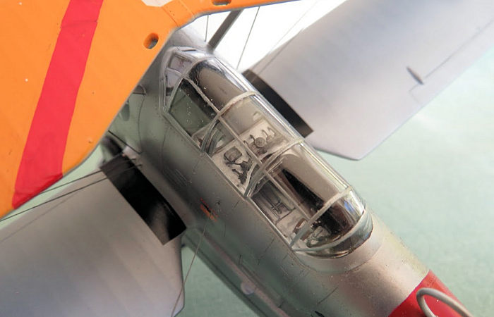 ed. I decided not to paint the
individual parts , but to assemble to entire cockpit section ( incl the Eduard
seat harnesses) and paint the lot according to the instructions afterwards.
ed. I decided not to paint the
individual parts , but to assemble to entire cockpit section ( incl the Eduard
seat harnesses) and paint the lot according to the instructions afterwards.
Step 2 : the main landing gear. In this case I wanted to build the plane with the landing gear retracted . The modeller who wants to do the wheels down option, has to be prepared to deal with a quite complex construction which does include making some of the supporting struts either from stretched sprue or use Evergreen polystyrene rods. The instructions give the size and length of these individual pieces.
Step 3: Fitting the complete cockpit assembly into the fuselage.This step required careful test fitting before closing up the fuselage. Needless to say that adjustments were necessary to get the fuselage shells to mate as good as possible. The square windows in the fuselage center also required a lot of adjustment to ensure a good fit . The instrument panel was slotted into place after the fuselage shells were joined.This was possible due to the fact that the fuselage front section is a separate item.
Step 4: This section deals with the horizontal and vertical tailplane. These bits come in two pieces each and , after glueing these together, some effort was needed to clean up the leading and trailing edges. That done, checking the interface between fuselage and the tail plane parts was important to ensure a as close as possible fit before cementing. Remaining gaps were filled with thin CA glue and sanded.
This was also a good time to dry fit the one piece canopy ( good access) A few small adjustments were necessary . After the canopy was glued on I took great care to mask off the canopy ( and the fuselage glazing).
Step 5: Deals with the fitting of the lower wings and cabane- and N struts. The same treatment as for the tail plane section is required here. To get the alignment of the struts correctly , I used a compass to measure the distance of the small holes engrave into the upper wing and positioned the struts accordingly. All the holes for the rigging were drilled at this point and I attached the rigging between the fore and aft cabane struts..
 Step 6: The outrigger floats were assembled , seams cleaned up and rivet lines
engraved. The alignment of the support struts was set by measuring the distance
between the holes engraved in the lower wings. The bracing wires were made of
.10 mm guitar string and glued into place with CA glue. This added more strength
to the structure as well.
Step 6: The outrigger floats were assembled , seams cleaned up and rivet lines
engraved. The alignment of the support struts was set by measuring the distance
between the holes engraved in the lower wings. The bracing wires were made of
.10 mm guitar string and glued into place with CA glue. This added more strength
to the structure as well.
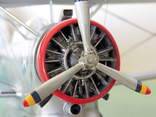
Step 7: I did not use the kit resin engine due to bad quality and installed a Vector P&W R 1820 resin engine instead. Pushrod tubes were made with pieces of guitar string . The ignition leads were fashioned out of copper wire.
I had to trim the rocker box covers in order to fit the radial into the cowl ring. I made sure that the engine had a light interference fit, just enough to keep the engine in position while dry fitting . The exhaust ring , carburettor intake and oil cooler intake were scratch built. The reason for doing this was because the kit parts were either not included or too small. And period photos show that the exhaust ring in particular was quite substantial.
The front portion of the fuselage caused some problems though. Glueing the two shells together was easy enough, but fitting onto the fuselage revealed some dimensional problems which could only be solved by copious amounts of putty and subsequent sanding and re-scribing of panel lines.
After this was done I stitched all the rivet lines onto the fuselage. As a guide I used my recently built Merit Grumman J2F 5 Duck. This was followed by further dry- fitting of the engine/ cowling and the exhaust ring. Held in place temporarily by masking tape I glued on my scratch-built carburettor and oil cooler intakes.
Step 8: Fitting the upper wing. To get this right I used masking tape to fix the position of the upper wing onto the locator pins of the struts and glued it together. After the glue had hardened I added some small drops of CA glue to fill small gaps and to add some more strength . The rigging was done using EZ line.
| COLORS & MARKINGS |
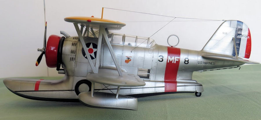
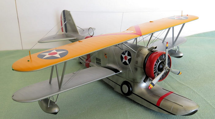
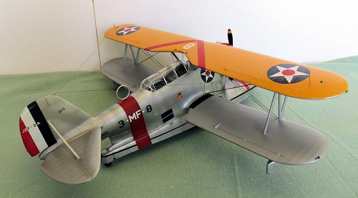
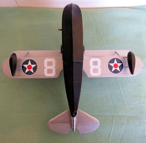 The upper wing was painted chrome yellow .The
fabric covered areas in flat aluminium and the fuselage and stabilizer floats
with AK polished aluminium. Undersides of the floats were painted black.
The upper wing was painted chrome yellow .The
fabric covered areas in flat aluminium and the fuselage and stabilizer floats
with AK polished aluminium. Undersides of the floats were painted black.
The decals were delicate to handle and were a bit brittle( age?) but I managed to apply the decals using Microsol decal solution.A thin coat of gloss clear sealed the decals. Weathering was applied mainly around the area behind the engine using pastels and Tamiya panel liner black and brown.
| CONCLUSIONS |
It was not a easy build. Some experience is needed to get the best out of the kit . But I am quite happy with the result. Can I recommend the CA kit? Well, yes but only to modellers who have the experience ( and patience ) to put in the extra work.
1 December 2020
Copyright ModelingMadness.com. All rights reserved.
If you would like your product reviewed fairly and fairly quickly, please
contact
the editor
or see other details in the
Note to
Contributors. Back to the Main Page
Back to the Review
Index Page
Back to the Previews Index Page