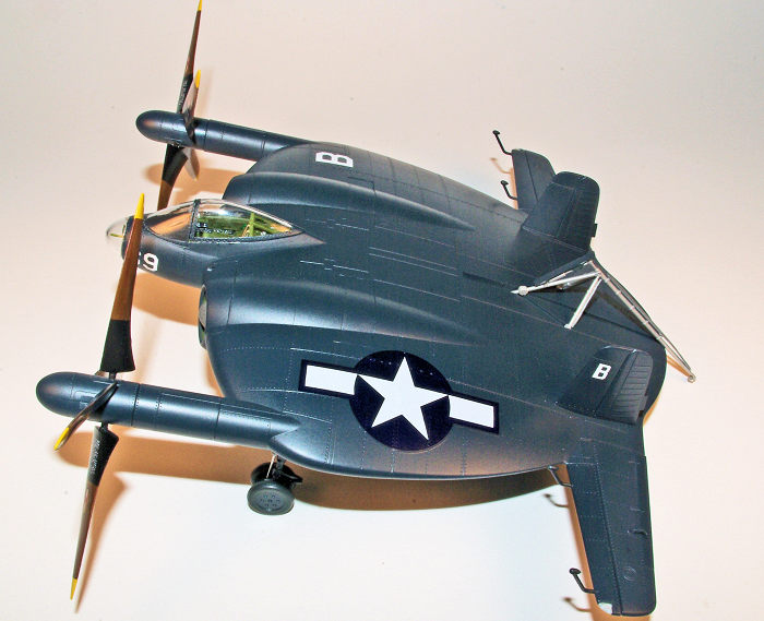
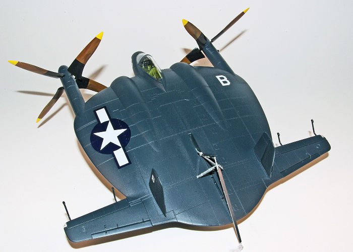
Kitty Hawk 1/48 XF5U-1
| KIT #: | KH 80135 |
| PRICE: | $56.99 SRP |
| DECALS: | Three options |
| REVIEWER: | Stephen Young |
| NOTES: | 2015 release |
| HISTORY |
The Chance Vought XF5U "Flying Flapjack" was an experimental U.S.
Navy fighter aircraft designed by Charles H. Zimmerman for Chance Vought
Aircraft during World War II. This unorthodox design consisted of a flat,
somewhat disc-shaped body (hence its name) serving as the lifting surface.
Mr. Zimmerman’s concept was that a aircraft design that used the propellers
to cancel the airflow vortices that occur naturally at the wing tips of a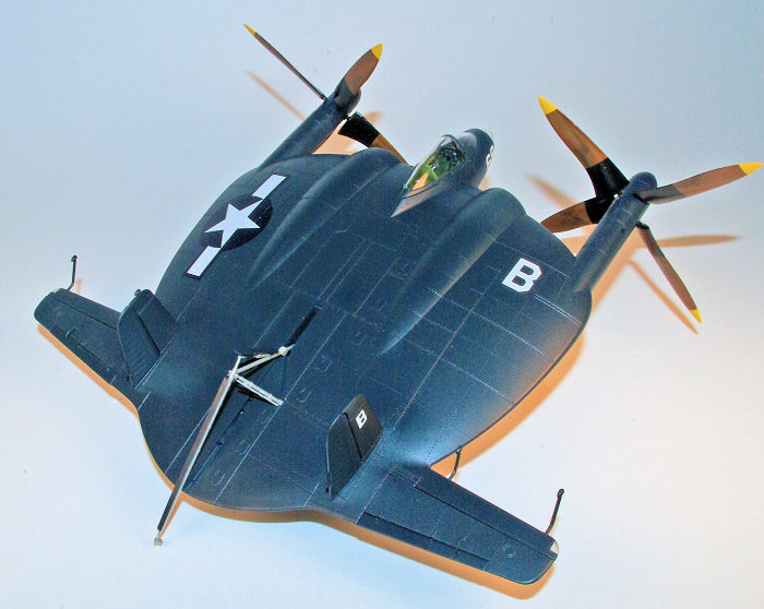 conventional aircraft resulting in enhanced lift with a much smaller wing
surface and facilitating high speed due to improved stream lining. Two
piston engines buried in the body drove propellers located on the leading
edge at the wingtips with the rotation direction opposite to the tip
vortices retaining the high pressure air below the wing. Developed from the
original flying prototype V-173, the XF5U was larger and of metal
construction with surface covering of metalite, a balsa wood/aluminum sheet
composite. Powered by two 1,600 hp Pratt & Whitney R-2000 radial engines,
the configuration was designed to create a low aspect ratio aircraft capable
of low take off and landing speeds but a high top speed. The propellers were
to have built in cyclic movement that Zimmerman termed “teetering blades”.
Although no armament was installed in the two prototypes it was envisioned
that the operational aircraft would be armed with six .50 caliber machine
guns or four 20mm cannon and up to 2,000 pounds of bombs or drop tanks. One
prototype for produced for static testing and although the other prototype
was used for limited taxi testing it never was flown. With the increasing
interest in jet aircraft the US Navy cancelled the contract on March 17,
1947 and both prototypes were subsequently destroyed.
conventional aircraft resulting in enhanced lift with a much smaller wing
surface and facilitating high speed due to improved stream lining. Two
piston engines buried in the body drove propellers located on the leading
edge at the wingtips with the rotation direction opposite to the tip
vortices retaining the high pressure air below the wing. Developed from the
original flying prototype V-173, the XF5U was larger and of metal
construction with surface covering of metalite, a balsa wood/aluminum sheet
composite. Powered by two 1,600 hp Pratt & Whitney R-2000 radial engines,
the configuration was designed to create a low aspect ratio aircraft capable
of low take off and landing speeds but a high top speed. The propellers were
to have built in cyclic movement that Zimmerman termed “teetering blades”.
Although no armament was installed in the two prototypes it was envisioned
that the operational aircraft would be armed with six .50 caliber machine
guns or four 20mm cannon and up to 2,000 pounds of bombs or drop tanks. One
prototype for produced for static testing and although the other prototype
was used for limited taxi testing it never was flown. With the increasing
interest in jet aircraft the US Navy cancelled the contract on March 17,
1947 and both prototypes were subsequently destroyed.
| THE KIT |
Released in 2015 Kittyhawk’s
1/48th scale XF5U-1 was a surprise from a relatively main stream albeit new
company producing a model of a aircraft that never proceeded past the prototype
stage. Other than the rare and difficult to obtain Hasegawa 1/72nd scale version
all other kits were produced as very limited run and sometimes rather expensive
kits. Kittyhawk’s version provides for a fictional operational aircraft and
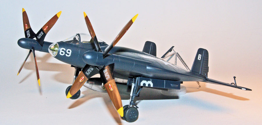
includes decal markings for three versions; two dark sea blue aircraft and a
natural metal version. Apparently removed from distribution due to copyright
issues were decals for a anime character version. The anime decal was literally
cut away from the included decal sheet that also provides a large and stern
image of “Uncle Sam” with the admonishment “I Need You” embellished with red and
white stars. Close inspection of the kit components reveals that some changes
and additional parts would be needed to reproduce accurately the one prototype
for which there is a photographic record. The most obvious changes needed
include: 1) plugging of the six machine gun ports (the prototype was never
armed), 2) installation of bulges in the outer landing gear doors, 3) revision
of the oleo strut prominent on each main landing gear leg, 4) change in main
landing gear wheel configuratio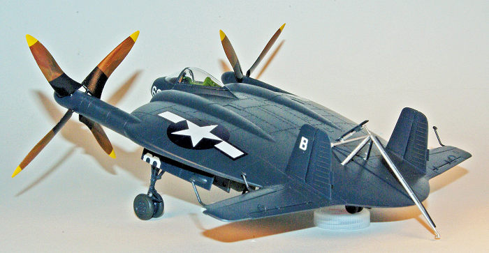 n
from the circular spokes to triangular spokes on the actual prototype, 5)
landing light in the nose omitted and 6) ventral mast and antenna cable may have
been present on the actual aircraft but reference photos are unclear on this
item. The kit also includes two 1,000 pound bombs and non-descript bomb racks
(Vought’s specification supported up to two 1,000 pound bombs or 150 gallon drop
tanks being carried). The kit includes four large sprues of parts molded in a
relatively soft, light gray plastic, a small sprue of clear parts, a small
photo-etch fret containing the cockpit seat harness, and two decal sheets.
Surface detail consists of finely engraved panel lines and recessed and raised
rivet detail. One of the unique features of the kit manufacturing is that the
sprue injection gates for the plastic parts are located on the flat or mating
surface of most parts that differs from most manufacturers that place the gates
adjacent to finish surface. A couple of the plastic parts (gun sight, elevator
horns) are extremely small and delicate and care must be exercised in removing
them from the sprue without damage. I find these difficult to clean up due to
their delicate nature and I found that I needed to change my removal method if I
were to use a sprue cutter and often used a very fine Czech Master razor saw
instead to separate the part from the sprue and then remove the excess plastic
with a sharp #15 scalpel blade. I decided to build a fictional operational
aircraft so proceeded with construction planning on using the dark sea blue
color scheme implemented by the U.S. Navy in June, 1944 that was destined to be
the basic specification for naval aircraft colors until 1947.
n
from the circular spokes to triangular spokes on the actual prototype, 5)
landing light in the nose omitted and 6) ventral mast and antenna cable may have
been present on the actual aircraft but reference photos are unclear on this
item. The kit also includes two 1,000 pound bombs and non-descript bomb racks
(Vought’s specification supported up to two 1,000 pound bombs or 150 gallon drop
tanks being carried). The kit includes four large sprues of parts molded in a
relatively soft, light gray plastic, a small sprue of clear parts, a small
photo-etch fret containing the cockpit seat harness, and two decal sheets.
Surface detail consists of finely engraved panel lines and recessed and raised
rivet detail. One of the unique features of the kit manufacturing is that the
sprue injection gates for the plastic parts are located on the flat or mating
surface of most parts that differs from most manufacturers that place the gates
adjacent to finish surface. A couple of the plastic parts (gun sight, elevator
horns) are extremely small and delicate and care must be exercised in removing
them from the sprue without damage. I find these difficult to clean up due to
their delicate nature and I found that I needed to change my removal method if I
were to use a sprue cutter and often used a very fine Czech Master razor saw
instead to separate the part from the sprue and then remove the excess plastic
with a sharp #15 scalpel blade. I decided to build a fictional operational
aircraft so proceeded with construction planning on using the dark sea blue
color scheme implemented by the U.S. Navy in June, 1944 that was destined to be
the basic specification for naval aircraft colors until 1947.
| CONSTRUCTION |
I enjoy building model kits
mainly in a out of the box format but my desire for ease of building often meets
the reality of needing to make a more realistic replica so some changes would be
needed. The instruction manual consists of fairly detailed diagrammatic
instructions following the recommended build sequence and are very clear. After
studying the instructions I decided to deviate from the recommended sequence due
to concerns about alignment of the slightly complex landing gear. Construction
begins with the cockpit tub and decals are provided for the instrument panel and
side consoles. The canopy is designed for a closed canopy build although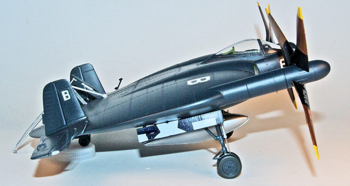 it can be built open. In the interest of keeping the finished model easier to
clean many of my builds are done with a closed canopy. Testors Model Master
Interior Green was used for all the interior parts except the instrument panel
and consoles. After painting, the painted surfaces were given a coat of Future
to provide a gloss surface for the decal application. The unpainted photo etch
seat harness was installed using cyanoacrylate glue and then painted. The next
build sequence calls for the main landing gear bays and the tail wheel bay to be
assembled including installation of all the gear components except the doors. I
assembled the bays but did not assemble the landing gear parts planning to
install the landing gear parts only after completion of painting. This provided
the advantage of avoiding inevitable breakage of the rather fragile parts,
simplifying the masking for painting, and allowing adjustment of the gear
installation to allow accurate orientation. After the gear bays were assembled,
the exhaust ducting was assembled and these components, together with the
completed cockpit were cemented to the lower fuselage half. Fit for the landing
gear bays was perfect and no issues were encountered. However, test fitting was
needed for the cockpit utilizing the top half of the fuselage to ensure correct
placement of the cockpit onto the lower fuselage half. Slight trimming of the
outside cockpit sidewalls was needed to obtain the optimum fit. Once this was
accomplished the cockpit tub was glued in place using Tamiya Extra Thin. After
the glue had set the attachment areas to the lower fuselage was reinforced with
a small amount of 5 minute epoxy to prevent any possible displacement. This was
followed by gluing the top fuselage half to the bottom again using Tamiya Extra
thin applied in small sections around the joint while maintaining alignment by
masking tape space around the periphery. Care in shaving away the sprue
injection gate plastic from the mating surfaces, careful test fitting and some
minor fine filing of the mating surfaces ensured a seam free joint. The engine
intakes were then installed and this provided the least precise alignment of
parts leading to some filling being required with my usual mix of thinned Bondo.
Several applications were
it can be built open. In the interest of keeping the finished model easier to
clean many of my builds are done with a closed canopy. Testors Model Master
Interior Green was used for all the interior parts except the instrument panel
and consoles. After painting, the painted surfaces were given a coat of Future
to provide a gloss surface for the decal application. The unpainted photo etch
seat harness was installed using cyanoacrylate glue and then painted. The next
build sequence calls for the main landing gear bays and the tail wheel bay to be
assembled including installation of all the gear components except the doors. I
assembled the bays but did not assemble the landing gear parts planning to
install the landing gear parts only after completion of painting. This provided
the advantage of avoiding inevitable breakage of the rather fragile parts,
simplifying the masking for painting, and allowing adjustment of the gear
installation to allow accurate orientation. After the gear bays were assembled,
the exhaust ducting was assembled and these components, together with the
completed cockpit were cemented to the lower fuselage half. Fit for the landing
gear bays was perfect and no issues were encountered. However, test fitting was
needed for the cockpit utilizing the top half of the fuselage to ensure correct
placement of the cockpit onto the lower fuselage half. Slight trimming of the
outside cockpit sidewalls was needed to obtain the optimum fit. Once this was
accomplished the cockpit tub was glued in place using Tamiya Extra Thin. After
the glue had set the attachment areas to the lower fuselage was reinforced with
a small amount of 5 minute epoxy to prevent any possible displacement. This was
followed by gluing the top fuselage half to the bottom again using Tamiya Extra
thin applied in small sections around the joint while maintaining alignment by
masking tape space around the periphery. Care in shaving away the sprue
injection gate plastic from the mating surfaces, careful test fitting and some
minor fine filing of the mating surfaces ensured a seam free joint. The engine
intakes were then installed and this provided the least precise alignment of
parts leading to some filling being required with my usual mix of thinned Bondo.
Several applications were
 made and
after sanding the Bondo was sealed with Mr. Surfacer 500 followed by final
polish sanding. In my experience the Mr. Surfacer dries with a density similar
to the plastic and ensures a invisible seam once final polish sanding is
performed. Any surface detail obscured was restored by scribing with a Czech
Master fine razor saw. The flying control surface components were then
assembled; note each horizontal stabilizer has a clear part representing a
light. Fit here was relatively poor and it was necessary to build up the lens to
be flush with the stabilizer surface using several applications of gap filling
cyanoacrylate cement and polish sanding. In retrospect it would be easier to
insert and glue a length of clear sprue of the same diameter of the hole and
then carve it flush with the surface and sand it smooth. Interestingly, on the
available photos of the prototype aircraft these lights are not readily visible.
The balance horns were left off for installation after final painting. The most
prominent and interesting components of the model are the large articulated
propellers. In the actual aircraft the blades were made of varnished mahogany
and close examination of the available black and white aircraft photos reveals
visible wood grain so finishing them with a simulated wood grain was a challenge
to be met. The hubs were assembled and the seams addressed but the blades were
cleaned up to be assembled only after painting was complete. Instead of using
the bombs and bomb racks provided in the kit a 1,000 pound bomb from a Monogram
P-38 and a 150 gallon drop tank from a Monogram P-61 was substituted. Once all
painting, clear coating, decal application and final clear coating was
completed, all the small parts including the intricate arresting hook assembly
were installed. The landing gear installation was fairly precise but leaving it
to late assembly allowed perfect alignment of both main struts that would not
have occurred if they were installed per the recommended build sequence. Parts
C26 and C27 are supposed to represent the landing gear dampers but comparison to
photos of the aircraft reveal they are completely incorrect. The kit parts look
like coil springs whereas the aircraft used a pneumatic or hydraulic piston.
This component is very prominent in the aircraft photos so replacements were
made from scratch using K&S 1/16 inch O.D. aluminum tubing, hypodermic needles
and the ends of the original plastic parts. Once attached to the front of the
landing gear legs with Tamiya Extra Thin and reinforced with a small amount of
cyanoacrylate they look much more realis
made and
after sanding the Bondo was sealed with Mr. Surfacer 500 followed by final
polish sanding. In my experience the Mr. Surfacer dries with a density similar
to the plastic and ensures a invisible seam once final polish sanding is
performed. Any surface detail obscured was restored by scribing with a Czech
Master fine razor saw. The flying control surface components were then
assembled; note each horizontal stabilizer has a clear part representing a
light. Fit here was relatively poor and it was necessary to build up the lens to
be flush with the stabilizer surface using several applications of gap filling
cyanoacrylate cement and polish sanding. In retrospect it would be easier to
insert and glue a length of clear sprue of the same diameter of the hole and
then carve it flush with the surface and sand it smooth. Interestingly, on the
available photos of the prototype aircraft these lights are not readily visible.
The balance horns were left off for installation after final painting. The most
prominent and interesting components of the model are the large articulated
propellers. In the actual aircraft the blades were made of varnished mahogany
and close examination of the available black and white aircraft photos reveals
visible wood grain so finishing them with a simulated wood grain was a challenge
to be met. The hubs were assembled and the seams addressed but the blades were
cleaned up to be assembled only after painting was complete. Instead of using
the bombs and bomb racks provided in the kit a 1,000 pound bomb from a Monogram
P-38 and a 150 gallon drop tank from a Monogram P-61 was substituted. Once all
painting, clear coating, decal application and final clear coating was
completed, all the small parts including the intricate arresting hook assembly
were installed. The landing gear installation was fairly precise but leaving it
to late assembly allowed perfect alignment of both main struts that would not
have occurred if they were installed per the recommended build sequence. Parts
C26 and C27 are supposed to represent the landing gear dampers but comparison to
photos of the aircraft reveal they are completely incorrect. The kit parts look
like coil springs whereas the aircraft used a pneumatic or hydraulic piston.
This component is very prominent in the aircraft photos so replacements were
made from scratch using K&S 1/16 inch O.D. aluminum tubing, hypodermic needles
and the ends of the original plastic parts. Once attached to the front of the
landing gear legs with Tamiya Extra Thin and reinforced with a small amount of
cyanoacrylate they look much more realis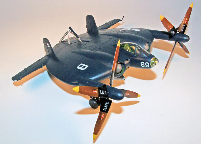 tic.
In addition, the outer main gear doors are missing a bulge (this existed only on
the outer doors, not the inner doors). This was added by cutting a section from
a thick cylindrical piece of sprue and gluing it in the correct position to the
door surface as referenced to photographs. Note that the gear door hinge parts
are individual and very delicate and care must be exercised in removing them
from the sprues and gluing them to the gear doors in the correct position. To
ensure a maximum strength join, all the hinge parts were glued to the bare
plastic gear doors using Tamiya Extra Thin cement and allowed to cure for
several days before handling. All small parts were individually painted by
airbrush prior to final assembly.
tic.
In addition, the outer main gear doors are missing a bulge (this existed only on
the outer doors, not the inner doors). This was added by cutting a section from
a thick cylindrical piece of sprue and gluing it in the correct position to the
door surface as referenced to photographs. Note that the gear door hinge parts
are individual and very delicate and care must be exercised in removing them
from the sprues and gluing them to the gear doors in the correct position. To
ensure a maximum strength join, all the hinge parts were glued to the bare
plastic gear doors using Tamiya Extra Thin cement and allowed to cure for
several days before handling. All small parts were individually painted by
airbrush prior to final assembly.
After wiping down the model with isopropyl alcohol to remove oil and residue the, landing gear openings and cockpit were masked off in preparation for painting. As a separate step all clear parts were carefully trimmed of flash and the sprue gates removed using a microsaw or sprue cutter followed by careful trimming with a sharp #15 scalpel blade before being dipped in Future and allowed to dry for at least two weeks. Note that clear part number xxx appears to be a unused part. The two part canopy was masked with Tamiya tape strips and Micro Scale Micromask and then attached to the fuselage using a small strip of Blue Tack. This would allow painting of the frame when the rest of the aircraft was painted.
| COLORS & MARKINGS |
After the model surface was
carefully wiped with a lint free cloth wet with isopropyl alcohol to remove
surface oils and removal of all fibers with a tack cloth, the model was
airbrushed with Tamiya Flat Aluminum acrylic thinned 50% with lacquer thinner
for the primer coat. I normally base coat with Rustoleum spray can gloss black
enamel but since this model was to be in a gloss Dark Sea Blue I wanted to
experiment with the Tamiya looking toward future use of this color for possible
paint chipping/wear under a camouflage paint. Rustoleum gloss Black enamel is
the same product available at Home Depot and most hardware stores in a large
aerosol can. Compared to most dedicated hobby paints it is very inexpensive per
volume. I decant this from the can into small jars and airbrush this usually
with minimal thinning with toluene using a Badger Anthem 155 airbrush at about
15 psi. (Note for safety purposes my workshop includes a 100 cubic foot per
minute outside venting spray booth and a 3M respirator with organic filters and
nitrile gloves are always used when airbrushing enamel or lacquer paints). The
finish is very glossy and in my experience gives good coverage. I allowed
several days for the base coating to dry before airbrushing Testors Model Master
Dark Sea Blue with ten drops of
 white
enamel added per ¼ ounce of blue paint and thinned about 30% with a 50/50 mix of
generic toluene and naptha. With this thinning ratio the paint density control
is excellent and provides perfect finish surface with very fine control. Two
thin color coats were applied and the goal was to have a minimally weathered
paint finish consistent with a relatively new aircraft. Since MM Dark Sea Blue
is a gloss paint no additional gloss coat is needed prior to decal application.
white
enamel added per ¼ ounce of blue paint and thinned about 30% with a 50/50 mix of
generic toluene and naptha. With this thinning ratio the paint density control
is excellent and provides perfect finish surface with very fine control. Two
thin color coats were applied and the goal was to have a minimally weathered
paint finish consistent with a relatively new aircraft. Since MM Dark Sea Blue
is a gloss paint no additional gloss coat is needed prior to decal application.
Trying to simulate a wood grain finish for the wood propellers was a new technique for me in modeling that had not been previously attempted. After studying various techniques found on the internet blogs, reviews, and YouTube videos, I decided to use artist’s oils for the task. I expected this process to be a challenge since part of the propeller near the hub is black and the tips are yellow. To simplify the process I decided to use Microscale yellow decal film for the tips. Each propeller blade was finish sanded and then primed with airbrushed Rustoleum gloss black. Once thoroughly dry, the entire propeller was airbrushed with Tamiya Acrylic XF-57 Buff thinned 25% with lacquer thinner. The propeller was then hand brushed using Windsor & Newton Burnt Umber oil paint thinned with toluene and a flat sable brush. Leaving brush marks was a desired outcome to simulate the wood grain. Due to the nature of the oil paint drying was allowed for about two weeks. Additional wood grain actually visible in the black and white photos of the XF5U-1 prototype with the articulated propellers was then simulated using Windsor & Newton Paynes Grey oil color applied with a fine 000 brush. Since this entire process was experimental several attempts were needed until I was satisfied with the results. After adequate time to dry the entire propeller was airbrushed with Testors GlossCoat lacquer thinned about 30% with lacquer thinner. I expected problems with lifting from masking for the black sections of the props but using but this turned out to be relatively minimal using 3M removable tape that has the same adhesive as 3M POST IT flags. Repeat airbrushing of the Testors GlossCote was needed on a couple of props but fortunately no color lifting occurred. Application of Microscale Insignia Yellow decal film provided the color for the tip.
The kit decal was used for the
large insignia and although thick it responded well to Microsol Microset and a
separate application of a small amount of Walther’s Solvaset to conform to the
raised rivet detail. On the undersurface the insignia decal needs to be measured
and carefully cut to allow placement to the fuselage undersurface as well as to
the gear doors. By June 2, 1945, Admiral John S. McCain, Commander of Task Force
38, had changed the tail and wing numbering system from symbols to block
letters. In conformance to this the model was marked with the letter “B” of the
U.S.S. San Jacinto, CVL-30, using Micro Scale 45 degree letters and assigned the
number “69”. In retrospect I probably should have applied the number “69” in
large numerals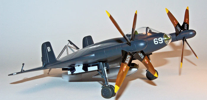 between the twin rudders as well but since there really were no operational
aircraft it would still be speculation. The kit decals include the black walkway
areas that are visible on pictures of the prototype. Apparently these areas were
actually a protective surface material actually taped to the surface of the
aircraft so presumably they would not have existed on an operational aircraft
and therefore they were omitted. After the decals were allowed to dry for
several days the model was then given two light coats of Testors GlossCote
airbrushed thinned 30% with lacquer thinner. As the coats are misted on with
care to avoid a “wet” coat no reaction with the enamel was encountered.
between the twin rudders as well but since there really were no operational
aircraft it would still be speculation. The kit decals include the black walkway
areas that are visible on pictures of the prototype. Apparently these areas were
actually a protective surface material actually taped to the surface of the
aircraft so presumably they would not have existed on an operational aircraft
and therefore they were omitted. After the decals were allowed to dry for
several days the model was then given two light coats of Testors GlossCote
airbrushed thinned 30% with lacquer thinner. As the coats are misted on with
care to avoid a “wet” coat no reaction with the enamel was encountered.
The complex landing gear parts were installed as were remaining small parts including a ventral pitot tube. To facilitate a reasonably strong bond a hole was drilled in the pitot tube base using a #80 drill and a short length of brass wire glued in place with CA glue. The pitot was then glued to the fuselage with a second #80 hole facilitating attachment. Handling the oddly shaped model was made simple by the use of egg crate style soft foam pads that I use for all my aircraft modeling in lieu of any stand or purpose designed rack. One must be very careful as final assembly proceeds to avoid parts breakage or misalignment while adhesive is setting. After all the underside parts were installed the canopy was removed, the masking removed and the area under the windscreen painted with Vallejo Nato Black. After the paint was dry the gun sight was attached followed by the canopy with Testors Clear Parts cement. The nose parts were then attached followed by the nose cone also attached with Testors Clear Parts cement. This was followed by the very delicate arresting hook assembly and the elevators with their balance horns. Lastly the large propellers were attached with a press on fit and no glue was needed allowing removal.
| CONCLUSIONS |
The XF5U-1 is one of the many experimental aircraft that arose out of the frantic search for military advantage during World War II that occurred on both sides of the conflict. Although the revolutionary aerodynamic concept proposed by Mr. Zimmerman never reached operational status it remains one of the more unique appearing curiosities of aviation. Kittyhawk’s early willingness to stray from the tried and true but often redundant kits of aircraft manufactured in multiple iterations provides a unique addition to any scale modeler’s collection and unique conversation piece. I would not recommend it for the absolute beginner due to the very small and fragile plastic parts and the need to deviate from the instruction assembly sequence but any moderately experienced modeler should have no difficulty. Sitting next to a Kyushu J7W1 Shinden, Horten, XP-55 or XP-58 it would look right at home on a flight line of “what if” aircraft of World War II.
| REFERENCES |
Naval Fighters Number 21, Chance Vought V-173 and XF5U-1 Flying Pancakes, Steve Ginter, 1992
1 March 2019
Copyright ModelingMadness.com
If you would like your product reviewed fairly and fairly quickly, please contact the editor or see other details in the Note to Contributors.
Back to the Main Page Back to the Review Index Page Back to the Previews Index Page