| KIT #: | ? |
| PRICE: | AU$6 (there were three in the box) |
| DECALS: | Almost a complete set |
| REVIEWER: | George Oh |
| NOTES: | A chop job |
| HISTORY |
During WWII, the aircraft of the Royal Navy were less-capable than those of the RAF. To compensate, the British eventually modified land-based Spitfire and Hurricane fighters in order to operate them off Royal Navy fleet carriers. The problem with the Spitfire/Seafire, was the narrow track of the undercarriage. The Sea/Hurricane was better. I’ve found no information, but I presume that belly-landing a Hurricane in water (aka, to ditch it), was forbidden because the Hurricane’s large ventral radiator would make first contact and most-likely cause the aircraft to tip over in the crash-landing, possibly/probably causing an injury to the pilot. The American P.51 Mustang (all variants) had an even larger belly scoop, which would have presented the same problems when ditching or belly-landing. In fact, the pilot's notes for the P.51 recommends abandoning the aircraft rather than electing to ditch it.
| THE KIT |
 I had bought
this started model kit from a (largely) model train shop that I passed on my
daily commute, because the Academy box had been sitting there for 2 years. Boy –
was I (and the Proprietor) surprised to find two more (equally started) in the
box. There were 3 fuselages and a mix of Academy and Hasegawa parts. None seemed
to be complete. There was one 90% decal sheet, but no instructions.
I had bought
this started model kit from a (largely) model train shop that I passed on my
daily commute, because the Academy box had been sitting there for 2 years. Boy –
was I (and the Proprietor) surprised to find two more (equally started) in the
box. There were 3 fuselages and a mix of Academy and Hasegawa parts. None seemed
to be complete. There was one 90% decal sheet, but no instructions.
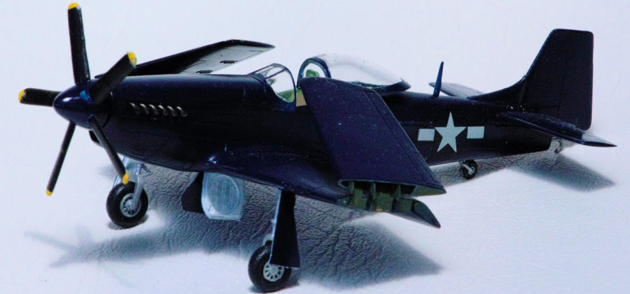
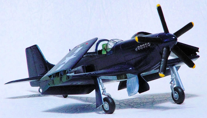
As a modeller, I've toyed with the idea of building a navalised P.51. Because I now had these three expendable kits, my imagination began to lead me (dangerous, I know) back to re-explore a P.51 Mustang for the US Navy, and my building could progress. I’ll not bore you with a description of this kit, or my build. Instead, I’ll tell you what I did, why I did it (and remember, I’m NOT an aeronautical engineer), and how I modelled it. Naturally, I modelled only external differences – not the internal engineering. We modellers can do that.
A navalised aircraft is generally distinguished, externally, by folding wings (for a smaller footprint when stored) and a tail hook (for arrested landings). The P.51D has neither of these. I had to plan the build as a whole, to incorporate all my modifications. The build centred around removing that dangerous belly scoop, and replacing it with something else, but keeping as much of a standard production aircraft, as possible.
| CONSTRUCTION |
 First thing I
did was remove the belly scoop with a razor saw, and that created a large hole
in the belly of the fuselage. I put thick plastic strips down the insides, then
I plated-over that hole with a piece of plastic card (and putty) that rested on
them. This allowed me to round-off the lower edges to make the curvature uniform
along the fuselage undersides. But that Merlin still had to be cooled, so I
scratch-built two smaller scoops from bits of chopped-up I-beam and plastic
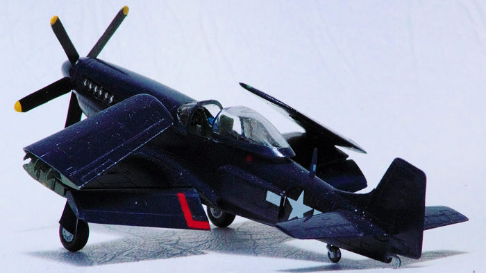
card, then mounted them P.38 Lightning-style onto the sides of the fuselage.
Each scoop still has the Mustang’s trailing flap.
First thing I
did was remove the belly scoop with a razor saw, and that created a large hole
in the belly of the fuselage. I put thick plastic strips down the insides, then
I plated-over that hole with a piece of plastic card (and putty) that rested on
them. This allowed me to round-off the lower edges to make the curvature uniform
along the fuselage undersides. But that Merlin still had to be cooled, so I
scratch-built two smaller scoops from bits of chopped-up I-beam and plastic
card, then mounted them P.38 Lightning-style onto the sides of the fuselage.
Each scoop still has the Mustang’s trailing flap.
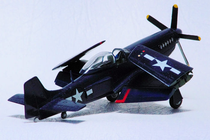
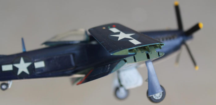
To fold my Mustang’s wings, I cut them chord-wise (from front to back) along the line between the aileron and the flap. It would have been silly to put the fold through the flaps or the ailerons (though some kit manufacturers think that it is perfectly OK to put a seam there). This will allow the outer half of the wings to fold in toward the cockpit canopy, F4U Corsair-style. And while I was hacking at the wings, I decided to scribe-off the flaps. When they were glued together, I put a thin strip between the halves (to extend the flaps rearward, a little) and a length of rod across the front to connect their leading edges, and to give the flaps their proper shape. The flap extensions were faired-in with putty, and their open sides were closed with thin plastic card.
The newly-exposed trailing
edges of the four inner wing halves were thinned to accept the rounded forward
edges of the flaps (because I wanted to reattach them in a dropped position. All
parked P.51s do that.) The halves were glued together where they touched - only
on the fuselage side and the leading edge, then those stubby inner wings were
mated to the fuselage. The inner wings needed to be solidified back into a
box-structure for strength. First, I inserted a ‘main spar’ near the trailing
edge. Then their
 open outer
faces were blanked-off with strips of thin plastic card (backed-up with bits of
sprue), ensuring that there were slots between them that corresponded to the
recessed panel lines on the surface of the wings. These slots would be needed
later.
open outer
faces were blanked-off with strips of thin plastic card (backed-up with bits of
sprue), ensuring that there were slots between them that corresponded to the
recessed panel lines on the surface of the wings. These slots would be needed
later.
Likewise, the newly-exposed faces of the wing tips were thinned, then they received some filler to fill-in the exposed open sides of the ailerons. Three narrow strips of thin plastic card were pushed into the wing tips along where the panel lines were on the outside, and glued in place. The protruding ends were then trimmed and rounded so as to appear to be able to insert into those slots of the inner wings so as to restore the initial structural strength of the wings.
How to mount the wings sturdily, in a folded configuration, stumped me for a long time, till I decided to superglue pieces cut from an old PE frame over two of the inner-wing end blanking-plates. The tops extended above the surface of the wing, and were bent inwards (a bit). The wing tips were superglued (with Gel) to the extensions. Identical blocks on top of the wing roots ensured that both wingtips were positioned identically in all 3 dimensions (4 if you understand that I did both at the same time). I left them overnight to dry securely in place.
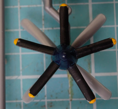 I planned
on a 5-bladed prop so that the plane had a little more clearance from the deck
during an arrested landing and from the ceiling when in storage. First, I filled
a spinner and three of the propeller-blade holes, with plastic bits, to make it
solid. Then, using a template, a jig, and that spared hole as a starting point,
I proceeded to drill the four other holes. As I had two 1-piece propellers, I
cut them apart and trimmed their bases to create a pin, which went into the
holes drilled into the spinner. Still with the jig and template, I shortened
each blade by the same small increment. All bits were painted before inserting
the 5 blades. No propeller area was lost - in fact, it increased a little.
I planned
on a 5-bladed prop so that the plane had a little more clearance from the deck
during an arrested landing and from the ceiling when in storage. First, I filled
a spinner and three of the propeller-blade holes, with plastic bits, to make it
solid. Then, using a template, a jig, and that spared hole as a starting point,
I proceeded to drill the four other holes. As I had two 1-piece propellers, I
cut them apart and trimmed their bases to create a pin, which went into the
holes drilled into the spinner. Still with the jig and template, I shortened
each blade by the same small increment. All bits were painted before inserting
the 5 blades. No propeller area was lost - in fact, it increased a little.
Initially, many naval aircraft had their arrestor hook were placed under the fuselage (Dauntless, Sea Hurricane and Seafire), but later ones had them placed near the extreme end of the tail (F4U Corsair, F14 Tomcat), or at it (F2A Buffalo, F4F Wildcat, F6F Hellcat). My model would follow this latter practice. First, I removed the two lower-most panels from the bottom of the rudder. To compensate, I extended the rudder chord-wise, with a strip of plastic card (as I closed the fuselage) – again, faired into shape with putty. This gave me a clear spot from-which I could extend the tail-hook.
A small idea was to dump the two the tail-wheel doors, and to replace them with a single piece in front of the tail-wheel to protect it from a possible arrestor wire strike. I discovered that Grumman also did this on the F6F Hellcat. Oh well – great minds, and all that………
| COLORS & MARKINGS |
I did the painting as I built her. Before closing the fuselage, the interior and main wing spar at the back of the wheel wells, were brush-painted with Citadel Miniatures (CM) loren forest green. Black, brown and other colours were used on the details inside of the office. Before I mounted the wing tips in their folded positions, the whole model was sprayed with Tamiya X-3 Royal Blue (to stand-in for the US Navy’s gloss sea blue), and the wheel wells were brush-painted with CM skull white, before being dry-brushed with CM admin (a light)grey.
 Decaling too,
was done before I mounted the wing tips in their folded positions, but only the
stars-and-bars were used. The only mod was to cut the forward bars from the side
markings, so that I could put them over part of those new side scoops. Oh –
there was that decal I used for the instrument panel, and the 2 red “KEEP OFF”
‘L’s on the flaps.
Decaling too,
was done before I mounted the wing tips in their folded positions, but only the
stars-and-bars were used. The only mod was to cut the forward bars from the side
markings, so that I could put them over part of those new side scoops. Oh –
there was that decal I used for the instrument panel, and the 2 red “KEEP OFF”
‘L’s on the flaps.
Last bits were 2 undercarriage legs, 3 wheels, 5 doors, 2 flaps, 1 antenna mast, 1 control stick, two canopy parts (one open, ‘cos I can!), 2 exhaust pipes, and I could see the Finish Line. I still had to drillout the tail and insert the tail hook. I also had to dot-on the formation lights, the fuel filler caps and the under-wing lights. When I attached the flaps, I sat the Mustang’s flat belly on a block so that both are lowered to the same degree.
| CONCLUSIONS |
I debated whether my Navalised Mustang should stick with 6 x 50Cal Browning HMGs or revert back to the 4 x 20mm cannons of the A.36 Apache. 20mm would have been better against ship-targets. In the end, I left that modification alone, because I didn’t want to have to do a lot more work, and I was running out of time (because I was trying to finish this for a P.51 Group Build). I totally enjoyed this build, but I reckon that there are some P.51 purists out there who are heating branding irons for me.
Who would give this aircraft its designation and name? The US Navy? North American Aviation? What would they choose? XFJ51DN (for eXperimental, Fighter, J/North American, 51D, Naval aircraft)? Sea Mustang? (too obvious. Not adventurous enough.) Seastang? S’tang? Tang? (a tropical reef fish. Nope – the Navy already have that for one of their Submarines). Seahorse? (nah – too tame, and no noseart potential). Sea Stallion? (nah – too long, but not for a big chopper). Mare? (nah – too short). Sea Mare? I’ve come to like Seastang.
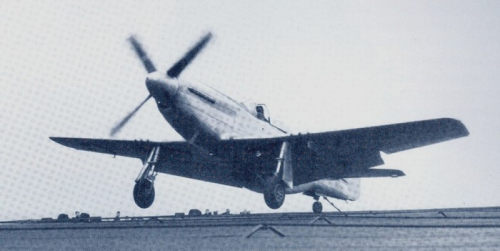 (For the
P.51 purists). In truth, the US Navy DID contemplate navalising the Mustang,
under Project Seahorse. They used P.51D-5-NA BuNo. 44-14017 (still in natural
metal) as the ETF-51D, and had test pilot LT Robert Elder doing trials during
Sep/Nov 1944 – first on Mustin Field, Philadelphia, then on the aircraft carrier
USS Shangri-La. It was beefed-up internally. Externally, it had a tail hook
between the tail wheel and the rudder post, and a catapult launch hook under the
belly (I’d better put one on mine), but the wings were still fixed. Project
Seahorse anticipated folding them and fitting them with tip-tanks, (I reckon
they were unnecessary), but the project was terminated after the US Marines
captured Iwo Jima and Okinawa, and the SeaBees had built the airbases required
by the USAAF. Anyway, the US Navy, and the USMC (for that matter), had the F6F
Hellcat and the F4U Corsair that were powered by radial engines which didn't
need the vulnerable fluid-based cooling system of the P.51's Merlin engine.
(For the
P.51 purists). In truth, the US Navy DID contemplate navalising the Mustang,
under Project Seahorse. They used P.51D-5-NA BuNo. 44-14017 (still in natural
metal) as the ETF-51D, and had test pilot LT Robert Elder doing trials during
Sep/Nov 1944 – first on Mustin Field, Philadelphia, then on the aircraft carrier
USS Shangri-La. It was beefed-up internally. Externally, it had a tail hook
between the tail wheel and the rudder post, and a catapult launch hook under the
belly (I’d better put one on mine), but the wings were still fixed. Project
Seahorse anticipated folding them and fitting them with tip-tanks, (I reckon
they were unnecessary), but the project was terminated after the US Marines
captured Iwo Jima and Okinawa, and the SeaBees had built the airbases required
by the USAAF. Anyway, the US Navy, and the USMC (for that matter), had the F6F
Hellcat and the F4U Corsair that were powered by radial engines which didn't
need the vulnerable fluid-based cooling system of the P.51's Merlin engine.
George Oh
20 June 2022
Copyright ModelingMadness.com. All rights reserved. No reproduction in
part or in whole without express permission.
Thanks to
for the review kit. You can find this kit at your favorite hobby shop or on-line
retailer. If you would like your product reviewed fairly and
fairly quickly, please
contact
the editor
or see other details in the
Note to
Contributors.