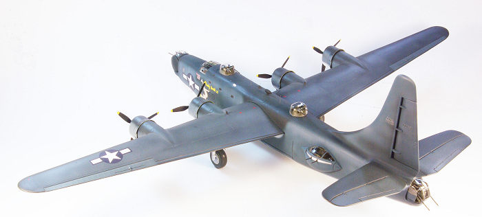
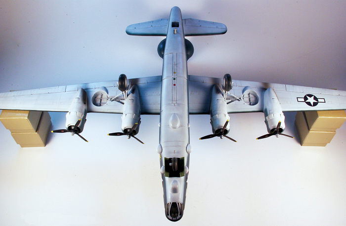
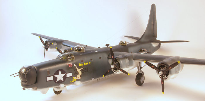
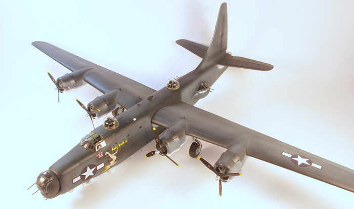
Monogram/Koster 1/48 PB4Y-2 Privateer
| KIT #: | 5604 |
| PRICE: | $39.00 for the kit, $39.00 for the conversion |
| DECALS: | One option |
| REVIEWER: | Stephen Young |
| NOTES: | Five figures - Motorcycle not included |
| HISTORY |
The Consolidated Aircraft Corporation B-24 Liberator
series of four engine bombers, although overshadowed in fame by the Boeing B-17
Flying Fortress, was the workhorse strategic bomber of the United States Army
Air Force in World War II. It was built in larger numbers and more versions than
any other WWII American aircraft although it faded rapidly from the scene after
the end of hostilities except in the U.S. Navy service. Immensely versatile, the
aircraft filled many roles as strategic bomber, transport, passenger transport,
tanker, and photo-reconnaissance and anti-submarine aircraft. It served in every
theater of the war and also in many Allied nations air forces as well. The
campaigns in which Liberators were flown and fought are legendary over Europe,
the Mediterranean, and the Far East. Less well known were the use of the B-24 by
the United States Navy as anti-submarine patrol aircraft in the Battle of the
Atlantic and their use as patrol bombers in the Pacific campaign. Prior to World
War II the U.S. Navy doctrine relied on flying boats for long range patrol
aircraft but as the war progressed the improved logistics of operating land
based aircraft led to selection of the B-24 due to its long range and ready
availability as a in production aircraft. The U.S. Navy Liberators were all
designated PB4Y-1s and the service received 997 aircraft starting with the B-24D
model with the greenhouse nose. The majority of Navy Liberators were D and J
models although some were L and M models with the Emerson A15 nose turret
or the Motor Products A6B turret. After combat experience demonstrated the
inadequacy of the glass nosed Liberator defensive armament, the Navy specified
modification of most subsequent aircraft to include the En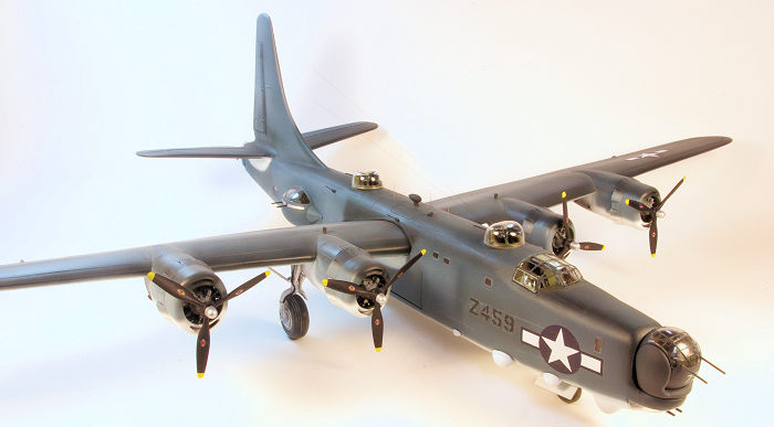 gineering
and Research Corporation 250SH-2 spherical ball turret that was a depot retrofit
to original green house nosed "D" aircraft. The 250SH-2 turret was originally
designed by Boeing Aircraft who furnished blueprints and manufacturing support
to Engineering Research. Navy PB4Y-1 squadrons were based throughout the western
and central Pacific flying search and strike operations (armed reconnaissance)
against Japan using the aircraft in ways the Consolidated engineers never
envisioned as Navy crews pushed these big, lumbering bombers down to altitudes
as low as 50 feet as a tactic to gain surprise, avoid enemy radar, and bomb and
strafe enemy ships at masthead height. As effective in this role as the
Liberators were the operational parameters of long range sea patrol the B-24 was
not adequately adapted using an engine and supercharger system unnecessary
for low altitude operations while lacking the capacity to carry the available
state of the art but bulky electronic equipment needed for maximum operational
effectiveness. The Navy canceled production of the Consolidated PB2Y-3 Coronado
flying boat to allow the company to build a modified B-24 reconnaissance
aircraft to be designated the PB4Y-2 Privateer. The new aircraft featured a
lengthened fuselage containing a seven foot long section inserted forward of the
wing containing a APS-2F, and later, -2G search radar along with AN/APN-4 long
range navigation electronics and additional electronic gear. Additional
defensive armament was added and the power plant optimized for low altitude
performance with removal of the supercharging system. Three prototypes were made
as conversions from B-24D aircraft and once a final configuration was accepted
the Navy contracted for 710 aircraft to be produced at a rate of 60 per month by
the end of 1944.
gineering
and Research Corporation 250SH-2 spherical ball turret that was a depot retrofit
to original green house nosed "D" aircraft. The 250SH-2 turret was originally
designed by Boeing Aircraft who furnished blueprints and manufacturing support
to Engineering Research. Navy PB4Y-1 squadrons were based throughout the western
and central Pacific flying search and strike operations (armed reconnaissance)
against Japan using the aircraft in ways the Consolidated engineers never
envisioned as Navy crews pushed these big, lumbering bombers down to altitudes
as low as 50 feet as a tactic to gain surprise, avoid enemy radar, and bomb and
strafe enemy ships at masthead height. As effective in this role as the
Liberators were the operational parameters of long range sea patrol the B-24 was
not adequately adapted using an engine and supercharger system unnecessary
for low altitude operations while lacking the capacity to carry the available
state of the art but bulky electronic equipment needed for maximum operational
effectiveness. The Navy canceled production of the Consolidated PB2Y-3 Coronado
flying boat to allow the company to build a modified B-24 reconnaissance
aircraft to be designated the PB4Y-2 Privateer. The new aircraft featured a
lengthened fuselage containing a seven foot long section inserted forward of the
wing containing a APS-2F, and later, -2G search radar along with AN/APN-4 long
range navigation electronics and additional electronic gear. Additional
defensive armament was added and the power plant optimized for low altitude
performance with removal of the supercharging system. Three prototypes were made
as conversions from B-24D aircraft and once a final configuration was accepted
the Navy contracted for 710 aircraft to be produced at a rate of 60 per month by
the end of 1944.
Patrol Bombing Squadron One-Hundred-Eight, VPB-108
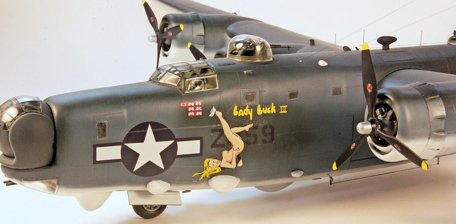
VB-108 was established at Naval Air Station San Diego on July 1, 1943. Equipped with PB4Y-1 Liberators, the squadron deployed to NAS Kaneohe Bay, Territory of Hawaii in October 1943 with subsequent combat deployment to the Pacific combat zone until relieved in July 1944. Redesignated Patrol Bombing Squadron 108 in October 1944 the squadron was equipped with the Privateer in February 1945 and began fitting two AN-M2 20 mm cannon to the nose of the aircraft and subsequently began combat operations from Peleliu Island, Palau in March, but subsequently moving to Iwo Jima in April 1945. Although this installation made the bombardier’s position unusable for bombing pilots were controlling the bomb release during the low level missions. By July the squadron had flown over 2,700 combat hours with the installation and claimed up to 40 percent more sinkings of small enemy ships using both incendiary and armor piercing rounds. The squadron’s last combat mission was flown on August 12, 1945. The subject of this build is VPB-108 PB4Y-2 Privateer BUNo 59459 named “Lady Luck III'' with expected pin up style art work.
Alan C. Carey’s books (see reference list) document the history of the U.S. Navy patrol bombing squadrons in the Pacific during WWII as brave men often flew single plane missions up to 1000 miles across the trackless Pacific; many crews were lost in combat or simply vanished without a trace. It was a dangerous war and hundreds of brave young men died flying and fighting in Navy Liberators and Privateers against the Axis powers.
| THE KIT |
 Monogram's
venerable 1/48th scale B-24D remains available in different boxing’s as
Monogram, Revell, and Revell Germany issues but is out of production
commercially.. Bill Koster’s Privateer conversion was first produced in the
early 1990’s and represented at that time a fairly complete solution to allow a
conversion built of either the Monogram B-24D or B-24J kit into a Privateer.
Either kit will work for this conversion with minor adjustments. The B-24D kit
consists of 156 parts including optional parts and figures and the B-24J kit
included additional parts for a M2 High Speed Tractor (M2 Cletrac). Panel lines
are raised and there is no rivet detail except on the bomb bay doors although
the real airplane surface was covered in raised rivets. The kit is rated skill
level 2 and the more recent production kit instructions are quite thorough and
clear unlike the old Monogram picture instructions included in the boxing I
used. Fit is fairly good except along the midline fuselage join where mis-alignment
is commonly encountered to a degree just sufficient to require some contour
filling work.
Monogram's
venerable 1/48th scale B-24D remains available in different boxing’s as
Monogram, Revell, and Revell Germany issues but is out of production
commercially.. Bill Koster’s Privateer conversion was first produced in the
early 1990’s and represented at that time a fairly complete solution to allow a
conversion built of either the Monogram B-24D or B-24J kit into a Privateer.
Either kit will work for this conversion with minor adjustments. The B-24D kit
consists of 156 parts including optional parts and figures and the B-24J kit
included additional parts for a M2 High Speed Tractor (M2 Cletrac). Panel lines
are raised and there is no rivet detail except on the bomb bay doors although
the real airplane surface was covered in raised rivets. The kit is rated skill
level 2 and the more recent production kit instructions are quite thorough and
clear unlike the old Monogram picture instructions included in the boxing I
used. Fit is fairly good except along the midline fuselage join where mis-alignment
is commonly encountered to a degree just sufficient to require some contour
filling work.
The Koster kit consists of three vacuform styrene sheets using 0.040 soft white styrene sheet and one clear vacuform acetate sheet. The kit includes parts to modify the Monogram kit with a choice of two nose turret options. Panel lines are engraved on the vacuum form parts and there are no rivets. Included are white metal cast parts and tan resin cast parts to allow one to fabricate the various turrets, plus resin engine parts for the Pratt & Whitney 1830R94 engines and the engine cowling faces, The instruction sheet is very basic with diagrams showing the parts needed including which original kit parts should be used and a diagram of where Bill Koster specified the original kit parts be cut to allow the vacuform replacement parts to be grafted on to create the Privateer fuselage and wing. Unfortunately, there are a number of inaccuracies in the conversion kit with regard to structures, dimensions, and features not provided or represented. There is much room for scratch building and miscellaneous construction since no detail parts are included (other than turret parts) and the conversion is not recommended for beginners.
Close examination of the vacuform part reveals some technical problems with the parts themselves. The most significant is that since the original styrene sheet thickness is 0.040 inch and some of the parts are relatively large requiring vacuum forming over a large master in some parts the resulting part thickness is as low as 0.008 inch equal to the thickness of index card paper. Examining closely one can see that part thickness will often vary within different sections of one part. This is especially true in several areas of the fuselage parts and the engine cowl and nacelle parts. This becomes important because building a fuselage up using the entire vacuformed part potentially leads to a very weak structure if not properly reinforced. In addition some of the parts are not completely accurate in dimension and my ability to determine accuracy is hampered by lack of accurate drawings of the aircraft. Other builders who have published reviews after building the conversion have reported issues including:
1. Inaccurate location for some of the small radar domes on the lower front fuselage
2. undersized engine nacelles
3. inaccurate representation of the main landing gear openings on engine nacelles number 2 and number 3
4. Inaccurate location for the engine exhaust outlets on nacelles #2 and #3
5. Incorrect location of mid fuselage windows - specifically on the port side the window spacing is incorrect and on the starboard side the two rear windows are too far apart.
6. The waist teardrop turrets are actually a scale 4 inches over size in diameter (they should be 54 inches).
7. No instruction or provision for the many antennas characteristically found on the Privateer. I was able to identify electronic systems that need representative antennas to include the following: a) APN-1 radio altimeter (two) b) liaison trailing antenna c) ARN-8 marker beacon antennas d) SCR-269G radio compass antenna e) ATB wire antenna f) ATC wire antenna g) APX-2 antenna (two) h) APC-5 VHF antenna
8. The Monogram wings have molded in wing tip formation lights molded into the top and bottom surface of each wing. This is incorrect for the Privateer as well as later model B-24 Liberators as the lights were replaced by single wing tip lights.
 9. Additionally as one recognizes upon building the
conversion there is a significant amount of imprecision from dimensional reality
that inevitably occurs as one cuts and splices various parts.
9. Additionally as one recognizes upon building the
conversion there is a significant amount of imprecision from dimensional reality
that inevitably occurs as one cuts and splices various parts.
Some of the inaccuracies were not corrected for various reasons including not recognizing the deficiency in time but are enumerated for full disclosure and to aid future builds of this conversion.
The cast resin parts were good quality in the early 1990s but are outclassed by the standard of the premier aftermarket cast part manufacturers today. There are some small surface bubbles in some parts randomly located that may need filling depending on the location. The same quality assessment can be made of the white metal parts also and for highest fidelity replacement of some, such as the machine guns, may be desired. The turret with the most noticeable inaccuracy is the tail turret. All Privateers had the same Motor Products tail turret in the A6B configuration and although some basic parts are provided in resin and white metal, the clear canopy is not correct as it omits the two small windows above the gun openings. The ERCO 250-SH spherical nose turret is more accurately represented and more so than the optional Consolidated nose turret but can be improved upon with a few additional fabricated parts. The last issue is that there are no Privateer propellers included and the instructions are to modify the Monogram B-24 kit paddle blade propellers to the correct shape for the Privateer. I substituted aftermarket cast resin propellers purchased from a vendor on the well known online auction specifically marketed as correct for the Privateer but the quality of the cast resin parts was very poor and much work was required to bring them to an acceptable appearance.
| CONSTRUCTION |
Before embarking on this work on a scale of difficulty of 0 to 5, I would rate the conversion for the average modeler to be a 10. A significant amount of custom fitting of vacuum formed parts and structural enhancements will be needed throughout the build process. Plus the builder will need to develop solutions to construction problems as they arise due to inadequate fit, alignment issues, and the basic level of engineering built into the vacuum formed kit and the conversion process. Moving ahead with the construction some of the solutions I implemented to fix identified problems were correct and helpful and some were not. All of it became part of the experience gained in building this model.
The Koster styrene vacuform parts were removed from the vacuum formed sheet using the standard technique of marking the outline of the part with a fine point Sharpie marker pen followed by scribing around the part with a sharp #11 scalpel blade. Care needs to be exercised since the first cut/scribe is the most important; if out of correct alignment the subsequent cuts will follow the first. Patience is needed as multiple passes with light pressure are best until at least the depth of the cut line is one half the thickness of the sheet. If this is your first experience with cutting out vacuform parts it can be a tedious process. Once the cut is sufficiently deep the excess plastic can be removed by bending the sheet away from the score line and the plastic will snap off. Of course there are corners and curves that make this process a little more complicated and one must be very careful to avoid applying breaking pressure against an insufficiently scored part or a fracture into the part can develop. The clear parts are not formed from styrene but a rather hard acetate vinyl material. These parts are removed from the sheet the same way but it takes much longer since the scoring cut must be done completely through the material and the material is much denser than the styrene. Attempting to break off a residual section of the material from the part can easily lead to a fracture into the part especially due to the relatively brittle nature of the material.
 Once the parts were free from the sheet each was
sanded on full sheet of #200 wet/dry sandpaper taped to a sheet of plate glass
until the black marker line was even all around each part. Final sanding was
done with a full sheet of #400 wet/dry sandpaper also taped to glass. Because of
the excessive thinning of the engine nacelle parts adjacent to where the resin
cowl part is to be attached, the area of the vac part adjacent to where the
resin part was to attach was reinforced by application of cyanoacrylate glue
mixed with dental resin (incidentally dental resin is quite expensive and can
not be purchased from dental suppliers except by bona fide dental practices). An
effective substitute is to use talcum powder with the CA cement which I
implemented half way through the construction process and found the resulting
mix was actually superior in working qualities.
Once the parts were free from the sheet each was
sanded on full sheet of #200 wet/dry sandpaper taped to a sheet of plate glass
until the black marker line was even all around each part. Final sanding was
done with a full sheet of #400 wet/dry sandpaper also taped to glass. Because of
the excessive thinning of the engine nacelle parts adjacent to where the resin
cowl part is to be attached, the area of the vac part adjacent to where the
resin part was to attach was reinforced by application of cyanoacrylate glue
mixed with dental resin (incidentally dental resin is quite expensive and can
not be purchased from dental suppliers except by bona fide dental practices). An
effective substitute is to use talcum powder with the CA cement which I
implemented half way through the construction process and found the resulting
mix was actually superior in working qualities.
The most important decision that needs to be made at this phase of the build is how to construct the fuselage. Several years ago Don Fogal documented his build of the Koster conversion on a modeling forum deviating from the Koster instructions with a very clever modification. His principle was to retain as much of the original Monogram kit fuselage structure as possible; as the kit parts are thick and strong, once assembled a very rigid structure results. This is important since the long wings attached to the mid-section of the fuselage pose a potentially structurally weak area especially if the bomb bay is built in the open position. To follow this build scheme you have to modify the Koster parts with additional sections being removed and reinforce the needed joints adequately while also making the corresponding modified cuts on the original fuselage parts.. The Koster method would instead cut away the rear Monogram fuselage just in front of the bomb bay and after of the bomb bay to add complete vacuform nose and tail/fin components. Again, it is the builder’s choice but in my opinion the loss of structural rigidity and strength was too excessive to justify following the original Koster plan.
As a result I ended up with the after upper fuselage decking and fin being a right hand and left hand component from the Koster parts, a mid-fuselage section to be inserted between the cockpit/nose and the bomb bay (much like on the original Privateer) and a separate distal nose section to provide the turret platform. If one uses a B-24J fuselage, you will also use a portion of the vacuform nose section although it can be somewhat longer.
The removal of the kit engine nacelles from the bottom section of each wing is the technically most difficult task that needs to be accomplished since care must be taken to preserve the attachment for the main landing gear. This is one of the visibly most inaccurate components of the kit as the number 2 and number 3 engine nacelles contain cut outs for the main landing gear and this is very inaccurately represented in the vacuform parts and is difficult to accurately reproduce when the original Liberator nacelle is cut away while preserving the landing strut attachment. Some other conversion builders have used the Vector products B-24 resin landing gear well to correct this per build reviews although I have not seen it in person.
Once the vacuform and original kit parts are cut, care must be taken to align the assemblies correctly to get a accurate match when the fuselage halves are joined and the wing top and bottom are joined. To facilitate cementing the vac parts to the original styrene sections the locating pins on the left half were cut off. The fuselage components were assembled with all parts resting on my construction bench flat surface.
The right and left nose sections were then attached to the fuselage halves using Tamiya Extra Thin (solvent) cement. With the rear section of the mid-fuselage addition this attachment is facilitated by a flange molded into the vac part. Where no flange was present the join was a butt join that requires reinforcement. After the assembly dried for 24 hours the areas needing reinforcement were reinforced with sheet styrene strips and cyanoacrylate cement mixed with dental resin.
The remainder of the fuselage assembly basically
followed the Monogram instructions so the cockpit areas and radio/flight
engineer compartment were assembled including the instrument panel, control
wheels, and pilot and co-pilot seat. I added photo etch parts using the Eduard
#49474 B-24D cockpit interior set making changes to correct for the differences
in controls and instrumentation in the Privateer. I also added sheet styrene
behind the pilot and co-pilot seats cut to represent armor plate. Since nothing
would be visible behind the cockpit no mid fuselage interior was added other
than the extension to the floor provided by the Koster vac kit. The interior
section behind the cockpit was painted dark green. The small windows were added
but since many historical images show the windows covered from the inside
(fitted covers were present for the actual production aircraft) I decided to
black out each window from the inside. Once the reinforcing strips and CA/resin
was cured the fuselage halves were strong enough to be handled but additional
reinforcement was needed because of the thin vacuform sections. This was
accomplished by using the Monogram kit bulkhead parts and these were all
cemented in place to the left side of the fuselage. In addition the bombay door
parts needed to model a closed bombay were cemented in place adding further
 mid
section rigidity. To reinforce the forward fuselage vacuform area in front of
the wing two lengths of 0.031 inch thick by 0.97 inch wide steel strip were cut
to fit and cemented in place with 5 minute epoxy to reinforce the side wall
area. A similar reinforcement was used for the vertical fin. The rear fuselage
interior was painted before the halves were joined. After priming the areas to
be painted with Rustoleum gloss gray enamel, the rear fuselage was airbrushed
with Tamiya Aluminum XF-16 as this area was natural aluminum on the aircraft but
would almost be invisible once the model was completed. The cockpit, nose, and
mid section compartment were airbrushed with Pactra Forest Green as an
approximation of the dull dark green used in the cockpit and the rest of the
forward interior would not be visible after completion.
mid
section rigidity. To reinforce the forward fuselage vacuform area in front of
the wing two lengths of 0.031 inch thick by 0.97 inch wide steel strip were cut
to fit and cemented in place with 5 minute epoxy to reinforce the side wall
area. A similar reinforcement was used for the vertical fin. The rear fuselage
interior was painted before the halves were joined. After priming the areas to
be painted with Rustoleum gloss gray enamel, the rear fuselage was airbrushed
with Tamiya Aluminum XF-16 as this area was natural aluminum on the aircraft but
would almost be invisible once the model was completed. The cockpit, nose, and
mid section compartment were airbrushed with Pactra Forest Green as an
approximation of the dull dark green used in the cockpit and the rest of the
forward interior would not be visible after completion.
The next step needed was to cut out the openings for the waist turrets. The Koster build instructions provide for each turret to be built as a separate assembly and then held in place using fabricated retainers. After considering the phases needed to complete the construction including painting, I decided to change to a different approach and build the turrets without the ability to move within the fuselage and build each turret after the fuselage was assembled. This would allow most of the painting and needed handling of the fuselage to be done without the risk of damaging the protruding turrets. The turret opening was cut out in the vacuform right and left rear fuselage parts. This needs to be done carefully as you will need the forward and rear fairing sections to complete the fuselage/turret construction. Once the turret openings were completed the vacuform rear fuselage section was used as a pattern to determine the position of the turret openings on the Monogram kit fuselage. It is necessary to assemble in place the kit supplied waist gun doors with their windows and this was done in advance as the fuselage was being prepared for assembly. Note that the Monogram B-24 kit has two small rectangular windows just forward of the waist gun openings and these will need to be filled as they do not exist on the Privateer. I cemented the original kit windows in place and filed down the framing even with the fuselage contour. Once the outline of the waist turrets was made with a fine point marker the opening was cut out using a Dremel tool and a cutting burr. Care is needed to make certain the opening that is cut out is just large enough to provide a 1/16th inch lip smaller than the size of the turret half to allow the turret halves to be cemented in place. The ERCO 250-TH turrets with their unique teardrop shape are provided in two sections divided longitudinally with outer component being clear acetate vinyl and the inner component white vacuform sheet styrene. Once the opening is the correct size the styrene section was cemented in place with Tamiya ET cement. Reinforcement internally was added on the interior side to insure a solid attachment as none of the interior fuselage will be visible (see photos). The Monogram fuselage has predominantly raised panel lines while the Koster kit parts have engraved panel lines although they lack sharpness. I elected to re-engrave all the most prominent lines to maintain consistency using the excellent Tamiya 0.2 mm engraving blade and knife handle. Most engraving was done at this point when the fuselage half components could be placed flat on a surface. I use egg crate configured soft foam pads to support my models as I build and together with a homemade support block the task of precision engraving is relatively simple and easy. I did not engrave rivets into the model surface. At this point the fuselage halves were ready to be joined. To assist in alignment small sheet styrene rectangles approximately 4 mm x 10 mm were cemented in place alternating the right and left fuselage halves placed strategically along the fuselage. Test fitting is needed prior to final joining as clearance of the various interior components must be assured. One of the issues with the original Monogram B-24 fuselage that anyone who has built the model can verify is the midline joint does not achieve perfect alignment along the entire length of the joint. Sufficient misalignment will occur that some recontouring and joint filling is needed. The presence of the additional vacuform sections adds even more to this task due to the difficulty of aligning surface contours of parts of different thickness.
This model would require weight to avoid tail sitting although Monogram provides a small boarding ladder to be used to prop up the tail. Fortunately the addition of the mid fuselage section provides a location to conceal the needed weight which I estimated to be approximately 2.5 ounces after dry fitting the major components together. This was achieved by gluing with 5 minute epoxy seven 0.36 ounce lead weights in place; four on the right half of the fuselage and three in the corresponding position on the left half at a location beneath the cockpit floor. Even this amount of weight was inadequate and eight were actually needed. Once the cockpit was completed including the photo etch parts, it was cemented in place into the right fuselage half with the join reinforced using 5 minute epoxy cement. Some additional support framing using the 0.031 x 0.97 inch steel strip was glued in place with 5 minute epoxy to strengthen the mid fuselage section.
The wings were next. The strength of each wing is of concern since they are quite long in relation to the width. In addition the Monogram kit engineering created an attachment tab pass through method for attaching each wing to its corresponding opening in the fuselage. Once built the structural integrity of the entire assembly depends upon the adequacy and strength of the cemented/glued tabs where they contact the fuselage tab openings and the strength of the midline fuselage joint especially on the dorsal surface. I decided to reinforce the wing by adding a spar of 1/8 inch square K&S brass tubing epoxied to the top half of each wing. This spar extended from the base of each wing almost to the tip. To add strength to the wing/fuselage assembly across the span of the fuselage 3/32 inch holes were drilled in corresponding points within the fuselage wing well and the base of each wing. This would allow a length of 3/32 inch solid brass rod to span the fuselage and reinforce the wings while simultaneously relieving stress across the dorsal midline fuselage joint.
The existing kit engine nacelles must be cut out to fit the Koster Privateer engine nacelles. This is one of the more difficult parts of the project and will require a significant amount of empirical fitting especially if one is to maintain alignment between the top and bottom of the nacelle halves once the two wing halves are assembled. After marking out the cut line using the Koster kit instruction diagram slightly under size to allow for fitting I used a Warp’s heavy duty plastic scribing knife to scribe the cut lines followed by jeweler’s saw to cut out the kit nacelles. Make certain you use a #4 (10 to 12 gauge) blade otherwise blade breakage will occur. This is tedious by hand and would be much easier on a small electric jig saw with a table.
The next step is multiple cycles of test fitting and trimming the wing cut outs to fit the vacuform nacelle parts while maintaining accurate alignment between the top and the bottom sections when the upper and lower wing sections are joined. Since the vac nacelle plastic is only about 0.030 inch thick at the joint line rectangular tabs of 0,040 sheet styrene to aid alignment and reinforce the joint when cemented with solvent cement. Needless to say joint filling and some contour correction is needed once the top and bottom wing sections and the corresponding nacelle sections are joined. Care must also be taken to fit around the main landing gear attachment holes. With the nacelle halves attached to the corresponding upper and lower wing sections, reinforcement of areas anticipated to be weak was done using 5 minute epoxy. Once cured the upper and lower wing sections and nacelles were joined and cemented using Tamiya ET. Due to fit issues some restoration of contours was needed and this was done using Green Stuff epoxy followed by additional contouring with Bondo although this would be more easily handled with the CA plus talc powder filling mixture.
 Each engine has a separate resin cowl ring and a
vacuform section containing the cowl flaps. The resin part needs to be glued to
the vacuform part and after the glue is cured the inside area of the cowl ring
must be trimmed to enlarge it sufficiently to allow the resin engines to be
inserted such that the reduction gear housing is just protruding beyond the face
of the cowl ring. No instruction or suggestions are provided on how to mount the
resin engines or the entire engine/cowl assembly onto the nacelle so some method
must be devised. My solution was to build a small jig to align the complete cowl
and the resin engine with the correct spacing. The engine is then glued in place
5 minute epoxy using two Plastruct 6mm U-channel stock cut in half lengthwise to
fabricate 90 degree angle strips that were then cut to the correct length to fit
inside the nacelle. Each engine should be separately labeled and matched to a
corresponding cowling. The entire assembly can then be directly mounted to the
face of the nacelle on the wing with some individual fitting and adjustment and
shimming with appropriate thickness sheet styrene spacers being required.
Obviously this requires test fitting and adjustments until you are satisfied
that the assembly is correct. The engines were primed with gray enamel paint and
carefully painted with Vallejo Acrylic paint. The cowlings require some seam
filling and minor contour work; I used Bondo automotive body putty and Vallejo
Acrylic putty with a finishing application of Mr. Surfacer 1000 and multiple
sanding although, again, for future work I would accomplish this with the CA
plus talcum powder mix.
Each engine has a separate resin cowl ring and a
vacuform section containing the cowl flaps. The resin part needs to be glued to
the vacuform part and after the glue is cured the inside area of the cowl ring
must be trimmed to enlarge it sufficiently to allow the resin engines to be
inserted such that the reduction gear housing is just protruding beyond the face
of the cowl ring. No instruction or suggestions are provided on how to mount the
resin engines or the entire engine/cowl assembly onto the nacelle so some method
must be devised. My solution was to build a small jig to align the complete cowl
and the resin engine with the correct spacing. The engine is then glued in place
5 minute epoxy using two Plastruct 6mm U-channel stock cut in half lengthwise to
fabricate 90 degree angle strips that were then cut to the correct length to fit
inside the nacelle. Each engine should be separately labeled and matched to a
corresponding cowling. The entire assembly can then be directly mounted to the
face of the nacelle on the wing with some individual fitting and adjustment and
shimming with appropriate thickness sheet styrene spacers being required.
Obviously this requires test fitting and adjustments until you are satisfied
that the assembly is correct. The engines were primed with gray enamel paint and
carefully painted with Vallejo Acrylic paint. The cowlings require some seam
filling and minor contour work; I used Bondo automotive body putty and Vallejo
Acrylic putty with a finishing application of Mr. Surfacer 1000 and multiple
sanding although, again, for future work I would accomplish this with the CA
plus talcum powder mix.
One of the mistakes made and not noticed until near the end of the build was that the wing located green and red location lighting on the B-24 was changed on the PB4Y-2 from being located on the upper and lower surfaces near the wing tip to a single light located at the end of the wing tip.
My build plan was to paint the wings and fuselage as separate assemblies and then join the components with only minimal paint touch up, weathering and clear coat being needed after that step. Therefore once the wings were assembled without the engine cowls attached, I added Eduard photo etch from Eduard #48618 to the main gear wheel wells and then the wings were painted.
Attention then returned to joining the fuselage halves. This was accomplished by carefully aligning the halves together as precisely as possible held together with rubber bands. Working along the joint a couple of inches at a time Tamiya ET was used to cement the halves together. After 24 hours of curing, the joint was reinforced where accessible through openings in the fuselage with CA plus dental resin. The Monogram fuselage for the "D" model provides a separate component to close the opening in the bottom of the fuselage just behind the bomb bay. A similar part with an opening for the Bendix belly turret is provided in the "J" model kit. This part requires fitting by trimming/filing/sanding for an optimal fit and was cemented in place with Tamiya ET. The Koster kit provides the horizontal stabilizer as a 3 piece assembly consisting of a full span upper section and a right and left lower section with an open bottom at the mid section. It requires structural reinforcement and I used wood medical tongue depressors narrowed toward the tips and glued to the upper section with 5 minute epoxy and joined together in the middle with epoxy. After fully curing the bottom sections were cemented to the upper section using Tamiya ET.
The area under the fin must be cut open and carefully trimmed for optimum fit to allow insertion of the horizontal stabilizer which was then cemented in place using a combination of Tamiya ET with 5 minute epoxy reinforcing the joints. Care must be taken to maintain the correct alignment of the stabilizer with the fin and fuselage. This is another area where the fit requires seam filling and this was accomplished using the CA/talcum powder mixture followed by application of Vallejo Acrylic putty for final filling.
In the nose section there is a defect in the vacuform molding of the right nose section as it is not as deep as the left. This required spanning a gap that was about ⅛ inch wide with sheet styrene and built up CA/talcum powder filling. Be certain to check the width since it needs to match the nose turret base exactly.
Turret construction notes:
Tail turret - The tail turret provided in the Monogram
Liberator D and J kits is incorrect for the PB4Y-2 Privateer. All Privateer
aircraft used the same Motor Products A6B tail turret which is open where the
guns extend from the turret and had no fairings covering the guns.
Monogram provides a very simplified closed turret representative of the Motor
Products A-6B turret but with aerodynamic fairings as normally used when the
turret was installed as a nose turret but less commonly seen on B-24s when
installed in the tail. No Privateers were equipped with the Emerson A-15
cylindrical turret. In addition the two clear parts are joine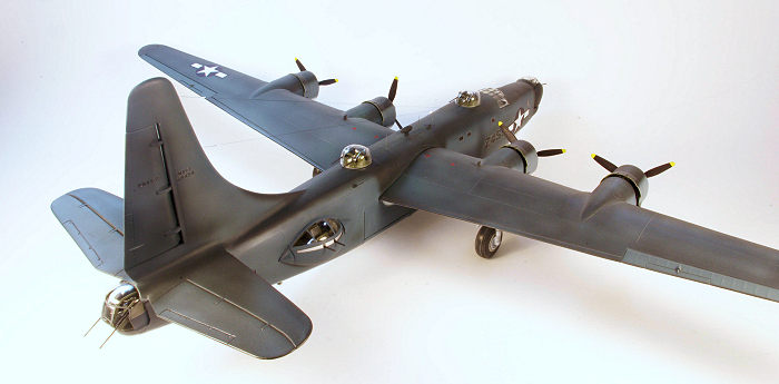 d with a seam
through the upper canopy of the turret and will not be hidden; on the real
turret this part of the turret canopy was one piece of plexiglass. The Koster
parts include resin, white metal and clear acetate parts to reproduce the A6B
turret without the fairings with one major omission; the two small, curved
plexiglass windows above the gun slots are missing. I decided to use the
Koster parts to avoid the transverse seam and the closed fairing configuration.
The resin turret interior parts were assembled with the addition of Evergreen
2.5 mm U channel stock to replicate the gun troughs. The interior parts of the
turret were airbrushed with Pactra Forest Green and a dark wash mix of one part
Future, one part water, Tamiya acrylic Flat Black XF-1, and Tamiya acrylic Red
Brown XF-64 was used. The vac clear parts are not precisely formed so careful
trimming and fitting is needed and despite that the fit remained imperfect when
glued in place using Testors Clear Parts Cement. Although the resulting turret
more closely represents a A6B without gun fairings for a more accurate
representation a new canopy will need to be vacuformed that includes the small
windows above the gun slots.
d with a seam
through the upper canopy of the turret and will not be hidden; on the real
turret this part of the turret canopy was one piece of plexiglass. The Koster
parts include resin, white metal and clear acetate parts to reproduce the A6B
turret without the fairings with one major omission; the two small, curved
plexiglass windows above the gun slots are missing. I decided to use the
Koster parts to avoid the transverse seam and the closed fairing configuration.
The resin turret interior parts were assembled with the addition of Evergreen
2.5 mm U channel stock to replicate the gun troughs. The interior parts of the
turret were airbrushed with Pactra Forest Green and a dark wash mix of one part
Future, one part water, Tamiya acrylic Flat Black XF-1, and Tamiya acrylic Red
Brown XF-64 was used. The vac clear parts are not precisely formed so careful
trimming and fitting is needed and despite that the fit remained imperfect when
glued in place using Testors Clear Parts Cement. Although the resulting turret
more closely represents a A6B without gun fairings for a more accurate
representation a new canopy will need to be vacuformed that includes the small
windows above the gun slots.
Nose Turret - Production Privateers from Bureau number 59350 to 59433 had Motor Products Corporation 250CH-5 (2 x 0.50cal. Cylindrical, hydraulic, model 5) turrets with the aerodynamic fairings similar to the Consolidated A6B turret. For BuNo 59434 through 60009 and 66245- through 66324 the Engineering Research Company ERCO 250SH-3 (2 x 0.50cal. Spherical, hydraulic) self-contained ball turret was installed after the aircraft left the Consolidated San Diego production line. The Koster kit provides both turret options but the Erco turret provides more complete part components. The spherical turret provides two halves of the sphere vacuformed out of clear acetate and right and left parts of the turret trunnion/ring as vacuformed styrene sheet parts plus a resin interior parts, a white metal control yoke and white metal machine guns. The Erco turrets were complex consisting of a 54 inch diameter sphere which contained the entire ammunition supply, the hydraulic motor, control mechanism, operator and the machine guns elevating/depressing on the trunnions. After cutting out the vacuform parts each was carefully sanded to the correct cut line. Care is needed here to test fit the two ball halves and the trunnion halves. In addition the trunnion halves have areas of very thin plastic due to the vacuum forming process. I decided to join the trunnion halves after careful fitting with Tamiya cement using small tabs of scrap sheet styrene to reinforce the joint along both the right and left sides of the trunnions. After this was cured I applied cyanoacrylate cement with dental resin to fill the trunnions in order to reinforce the joints as well as along the turret ring part of the joints. Once this was cured all excess plastic was carefully removed and the ball turret portion and the trunnion portion were constantly test fitted to avoid removing too much material from the trunnions. This is where the Koster quality is appreciated as the dimensions are quite close for the vacuform parts. I decided to add some scratch details to the interior such as a seat, backrest/armor, and restraint belts as the interior is completely visible through the large turret canopy. It is very important to note that the manner in which the two ball halves are engineered, because when the turret is finished, the bottom half is raised at the rear and the top half is depressed at the front. This serves to hide the seam in the non-transparent front of the turret behind the front of the turret ring. The rear seam then consists of the turret canopy and the back of the turret. I cut a circular wall piece of 0.010 sheet styrene that fit exactly inside each portion of the parallel sides of the ball halves. This was glued with CA to the inside of each acrylic turret half. This wall provided the foundation to frame the turret interior using Evergreen strip styrene. It is important to note that when you build this up, the bottom half of the turret must be angled to account for how the turret will sit within the trunnions in its normal horizontal resting position. A circular turret floor with the sides cut away to fit between the walls was added using 0.010 sheet styrene. The gun mount is provided by the resin components and the entire assembly was glued to the floor at the front of the turret. Additional .010 sheet styrene was cut to represent the armor/backrest and glued with CA to the back of the lower half of the turret. A seat was then added as well as a control yoke and a sight bar using copper wire and a piece of clear sprue for the sight. A lot of care must be taken to fit in the guns since they will protrude through two holes in the clear canopy portion of the turret. Lots of test fitting is needed here. The turret interior was then airbrushed with interior green, small parts painted as needed, and the dark wash applied. The canopy half of the turret was given a treatment with Future floor polish and after drying painted before attachment. The clear portions of the inside were masked off using Tamiya tape and then the interior, which will be visible, was airbrushed interior green. The exterior canopy was masked off using Bare Metal foil and then airbrushed with MM Interior Green followed by MM Dark Sea Blue. After drying the masking was removed. The guns were test fitted and glued in place with CA followed by gluing the clear portion on using 5 minute epoxy applied overlapping the flat surface adjacent to the trunnion. The finished turret actually looks pretty good once assembled to the trunnion with a light press fit.
 Dorsal turrets - The Koster Martin dorsal turret
includes the vacuform clear turret dome, three resin parts and white metal
machine guns. Most will not be well seen once installed. The resin parts were
attached to the resin turret ring with the aid of fine guitar wire posts
installed in #80 holes. Despite trimming of the lower front portion of the resin
part representing the ammunition boxes it was not possible to allow the turret
to fit into the fuselage through the opening so it was necessary to remove the
seat component. This wasn’t the best solution but fortunately unless one is
looking directly down onto the top of the turret the seat is not visible. Note
that the Monogram B-24D turret is not the correct dome for the Privateer
turret.
Dorsal turrets - The Koster Martin dorsal turret
includes the vacuform clear turret dome, three resin parts and white metal
machine guns. Most will not be well seen once installed. The resin parts were
attached to the resin turret ring with the aid of fine guitar wire posts
installed in #80 holes. Despite trimming of the lower front portion of the resin
part representing the ammunition boxes it was not possible to allow the turret
to fit into the fuselage through the opening so it was necessary to remove the
seat component. This wasn’t the best solution but fortunately unless one is
looking directly down onto the top of the turret the seat is not visible. Note
that the Monogram B-24D turret is not the correct dome for the Privateer
turret.
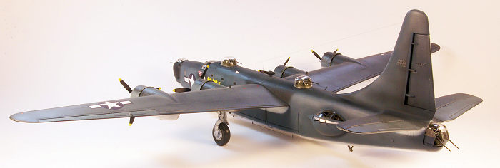
Waist turrets - The ERCO 250TH (2 x 0.50 cal. Teardrop, hydraulic) waist turrets are one of the most unique and interesting features of the Privateer and they were installed on no other production U.S. war plane. Each is a hydraulic powered unit consisting of a teardrop shaped shell that contains an independently rotating turret basket built on a steel tube frame housing the two machine guns. Ammunition was supplied through tracks entering the tail end of the turret from large boxes located toward the tail of the aircraft. Kosters turret parts consist of the vacuformed styrene and acetate shell halves, a vacuformed upper and lower keel, armor, resin turret basket, white metal turret basket support, ammo feed, and machine guns. Although the detail is not accurate it builds into a reasonable representation. As noted above instead of building the turrets as complete units I decided to assemble the turrets after the fuselage was completed surmising that the visual result would be the same but the construction and importantly, the avoidance of breakage during handling for painting and finishing would be important. The gun barrels were cut off and locating pins using fine guitar string wire were inserted into the end of the barrel. Once completed the gun barrels were inserted through holes drilled in the gun band and the pin placed in the corresponding hole in the gun assembly.
| COLORS & MARKINGS |
The model was painted in assemblies doing the fuselage/stabilizer and wings separately since with everything attached the model is large and unwieldy to handle. SR-2C, Specification for Exterior Colors, Insignia, and Marking of Naval Aircraft, January 5, 1943, specified what is commonly known as the tri-color scheme. This consisted of semi-gloss and non-specular (flat) sea blue upper surfaces, intermediate blue sides, and non-specular (flat) white under surfaces. Spot priming was done with decanted Derusto aerosol can gloss gray enamel paint to allow identification of areas needing additional filling and contouring. This was done over multiple repeat cycles until the surface defects were eliminated. Panel lines were rescribed as needed. This was followed by pre-shading panel lines with decanted Rustoleum gloss black enamel. To do the tri-color scheme I sprayed Rustoleum gloss white, Tamiya Medium Blue XF-18 and Tamiya Dark Blue XF-17 base coats. There are very few color photos in existence of Pacific theater Privateers; most photos are black and white and show severe fading of the Dark Sea Blue upper surface color. In addition the airplanes were very weathered and dirty operating from forward island bases. Besides a basic tricolor scheme some Privateers were painted in a variation that mottled Dark Sea Blue over the intermediate blue of the fuselage sides. One needs to check reference photos on the aircraft being modeled. The nose art came from the Koster kit decal set and was hand embellished by me for an improved appearance by coating the decal on the intact sheet with Microscale liquid decal film then free hand painting additional color shading and highlights with Vallejo acrylic paint. After drying the decal was painted with a final coat of the Microscale liquid decal film solution. Once dry it was ready for application. Insignia decals were sourced from the Superscale USAAF insignia WWII Blue Borders (#MS481266) sheet with the number markings from the Koster kit supplied sheet and the surplus decal collection for the number on the nose turret. Note that the correct location of the national insignia on the wings is a scale 17 feet 4 inches from the wing tip. After viewing every photo image of wartime Privateers that I could find that showed the wing insignia I concluded that the 1/48 scale 40 inch insignia was the correct size although one could make a case for a 45 inch insignia. Decals were applied using the Microscale system and technique although persistent micro-bubbles and wrinkles in the decal required treatment with Walthers Solvaset thinned 25% with distilled water. After decals were applied, two light coats of Future thinned 20% with plain vodka (40% ethanol/60% water) was applied followed by weathering using pastel chalk, Tamiya panel liner black and gray as well as Tamiya smoke airbrushed for the exhaust staining. Once completed the entire model was given two light coats of Testors Dullcote clear lacquer thinned 20% with lacquer thinner.
The model then proceeded to the final assembly of the
turrets, the wings to the fuselage, landing gear, multiple antenna, canopy,
propellers and other parts. I used the Monogram kit canopy that consists of
three pieces although the fit is not perfect and required some gap filling with
Testors Clear Parts Cement. All clear parts were dipped in Future floor finish
and dried for at least two weeks (the longer the better in my experience) prior
to painting. To add interest I built up the instrument panel attached to the
overhead midline portion of the canopy using lead wire and lead solder, sheet
styrene and small pieces of scrap styrene sheet to repres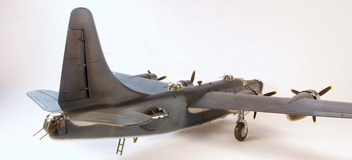 ent components of the
overhead instrument panels. All clear pieces were attached with Testors clear
parts cement. The frame was masked with Bare Metal foil and airbrushed with
Testors Model Master Interior Green followed by Tamiya Sea Blue XF-17 lightened
with Tamiya X-2 White. The wing halves were next. On the fuselage box where the
wing is inserted there are three slots to align with the wing tabs; the left
wing has one tab and the right wing has two. When correctly aligned these tabs
solidly lock the position and correct dihedral of the wings. A 6 inch length of
K&S 3/32 inch solid brass rod was inserted into holes drilled in the wing root
to support the wing joint. The next step was attaching the main landing gear
assemblies and these fit into cone shaped openings in the lower wing/inner
engine nacelle area. The fit was very loose so care is needed to hold alignment
while the join sets; I used 5 minute epoxy for its speed and adequate working
time as well as a heavy paper card template to obtain the correct angle.The fit
of the landing gear strut doors required some trimming to be attached after the
main strut was glued in place.
ent components of the
overhead instrument panels. All clear pieces were attached with Testors clear
parts cement. The frame was masked with Bare Metal foil and airbrushed with
Testors Model Master Interior Green followed by Tamiya Sea Blue XF-17 lightened
with Tamiya X-2 White. The wing halves were next. On the fuselage box where the
wing is inserted there are three slots to align with the wing tabs; the left
wing has one tab and the right wing has two. When correctly aligned these tabs
solidly lock the position and correct dihedral of the wings. A 6 inch length of
K&S 3/32 inch solid brass rod was inserted into holes drilled in the wing root
to support the wing joint. The next step was attaching the main landing gear
assemblies and these fit into cone shaped openings in the lower wing/inner
engine nacelle area. The fit was very loose so care is needed to hold alignment
while the join sets; I used 5 minute epoxy for its speed and adequate working
time as well as a heavy paper card template to obtain the correct angle.The fit
of the landing gear strut doors required some trimming to be attached after the
main strut was glued in place.
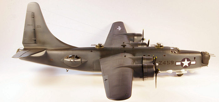
The Privateer was equipped with a large suite of state of the art electronics gear including search radar, navigation systems, communication and electronic countermeasure systems resulting in multiple antennas and fairings protecting them all over the aircraft. Several of these provided the Privateer with its iconic appearance. One of the major shortcomings of the conversion kit is the ventral radome for the APS-2F, -2G search radar that is supplied as a cement on part representing the radome in the partially retracted position. In fact it was fully retractable and more accurate representation would require a correctly shaped radome bay and a separate radome. I did not correct this feature on this build. The communication antenna wires fabricated using Infini line (70 denier-0.091mm) attached to a 4 mm length of brass tubing representing the insulator near the fin. Fine E-Z line was then attached to a 4mm length of Albion Alloys micro brass tube (0.5mm x 0.3mm i.d.) then attached to holes drilled with a #80 bit in the vertical fin.
Having space to display a model this large is problematic. My solution used was to leave the model as separate sub-assemblies (fuselage, port and starboard wings, turrets) and assemble when desired for display or photographing. When disassembled the model components are held in the construction board jig used for assembly.
| CONCLUSIONS |
My interest in the Privateer grew out of an obsession with the Consolidated B-24 ever since I was a young boy fascinated by the service of my father in the United States Army Air Force. The venerable Monogram series of B-24D and B-24J kits remains the only versions in 1/48th scale although outdated in many aspects of fit, detail, and engineering compared to most leading kit manufacturer’s current offerings. It is a certainty that any new mold kit in this scale would be much more expensive although probably bringing much better detail and engineering. The real question is whether a new kit of a B-24 variant will ever be manufactured in this scale. The Revell/Monogram kit has many over simplified features and some visible but significant inaccuracy issues but the part count is low and it builds up into an impressive model out-of-the-box due to size alone although it benefits from as much modeling skill as one can muster. With skill and effort as well as aftermarket parts it can provide the basis to build an excellent model. The Koster conversion complicates the build significantly but other than the rare Cutting Edge resin conversion and a couple of other lower quality conversions, it remains the only way to build a Privateer without complete scratch building .
| REFERENCES |
1. Above An Angry Sea, United States Navy B-24 Liberator and PB4Y-2 Privateer Operations in the Pacific, Alan C. Carey, Schiffer Military History, 2001
2. Convair PB4y-2/P4Y-2 Privateer, Naval Fighters Number Ninety-three, Nicholas Veronico & Steve Ginter, 2012
3. Consolidated PB4Y-1/1P Liberator, Naval Fighters Number 105, Steve Ginter, 2017
4. ERCO, Engineering and Research Corporation, Chuck Hansen, American Aviation Historical Society, Vol. 30, No. 1, Spring, 1985
5. B-24 Liberator in Detail, Bert Kinzey, Vol. 64, Squadron/Signal Publications, 2000
6. B-24 Liberator in Action, David Doyle, Squadron/Signal Publications, 2012
November 2020
Copyright ModelingMadness.com
If you would like your product reviewed fairly and fairly quickly, please contact the editor or see other details in the Note to Contributors.
Back to the Main Page Back to the Previews Index Page Back to the Review Index Page