Hasegawa 1/32 P-47D Thunderbolt
| KIT #: | St 27 |
| PRICE: | $65.00 |
| DECALS: | Two options |
| REVIEWER: | John Summerford |
| NOTES: | 2007 boxing, decals from EagleCals, instrument panels from Yahu, and cockpit details from Eduard |
| HISTORY |
 The P-47 was
culmination of a series of fighters developed for USAAC from the mid-1930s
through World War Two. Seversky Aircraft Corporation developed the P-35 which is
noted as the first all-metal, retractable landing gear, enclosed cockpit fighter
in the US Army Air Corps. That design was followed up by the P-37 featuring a
turbocharged engine. After a corporate re-organization and name change to
Republic Aviation, The P-47 design used experience gained with turbocharging and
the new P&W R-2800 engine. This gave the plane excellent high-altitude
performance.
The P-47 was
culmination of a series of fighters developed for USAAC from the mid-1930s
through World War Two. Seversky Aircraft Corporation developed the P-35 which is
noted as the first all-metal, retractable landing gear, enclosed cockpit fighter
in the US Army Air Corps. That design was followed up by the P-37 featuring a
turbocharged engine. After a corporate re-organization and name change to
Republic Aviation, The P-47 design used experience gained with turbocharging and
the new P&W R-2800 engine. This gave the plane excellent high-altitude
performance.
Francis Gabreski was the highest scoring pilot in Europe with 26 planes shot down, all while flying the P-47. Ironically, the greatest success of the P-47 was as a low-level bomber and strafer. The rugged airframe and air-cooled engine allowed badly shot-up planes to fly the pilots home. The 9th Air Force wanted as many of the planes as they could get.
Lieutenant Joseph “Ray” Murphy
On December 26, 1944, Lt. Murphy shot down a Fw-190 and damaged another, he was then forced back to base due to engine damage. 47 years later, Murphy was credited with a second air victory, this brought his total wartime tally to 2 enemy aircraft destroyed and 20 enemy vehicles and most impressively, a whopping 31 locomotive cars destroyed in a single mission. As a, pilot for American Airlines Murphy had an engine explode during a flight on April 12, 1959. He managed to control and land his airline safely. For this, he was awarded the Medal for Value and Distinguished Services.
| THE KIT |
 Sprues are
sealed in two bags. One bag holds mostly the main frame parts and the second bag
holds the detail parts. A third bag has the clear parts and is inside the first
bag. Total parts count is 172. The kit does not have any photo-etch parts.
Options include a pilot figure, two different types of drop-tank, Hamilton
Standard or Curtiss electric prop, (I identified each one by the logo decal
called for.) open or closed canopy, open or closed turbo vents, flaps up or
down, and open or closed cowl flaps that have plastic in the gaps. Mold seams
are minimal and flash is not present. Detail is petite and panel lines are
recessed.
Sprues are
sealed in two bags. One bag holds mostly the main frame parts and the second bag
holds the detail parts. A third bag has the clear parts and is inside the first
bag. Total parts count is 172. The kit does not have any photo-etch parts.
Options include a pilot figure, two different types of drop-tank, Hamilton
Standard or Curtiss electric prop, (I identified each one by the logo decal
called for.) open or closed canopy, open or closed turbo vents, flaps up or
down, and open or closed cowl flaps that have plastic in the gaps. Mold seams
are minimal and flash is not present. Detail is petite and panel lines are
recessed.
The decal sheet is huge at 7 ½ inches by 15 ¾ inches. It has cockpit details and markings that include D-Day stripes. One can model Gabresky’s plane illustrated on the lid, or Major Glenn Eagleston.
A brief history in English and Japanese plus a parts map can be found on the first page of the 12-page instructions. Assembly is completed in 16 steps. Paint call-outs are for Humbrol colors and some also include FS codes.
| CONSTRUCTION |
Once again, the build starts with the cockpit. Since
it is very easy to see into this area, I used the Eduard detail set to replace
the sidewall details and also for the seat harness. I used this build to try a
Yahu instrument panel and I find it less difficult to install than the Eduard
panel and that it looks better too. After all the details were added and
painted, the components assemble quickly. The tub attaches to the wing spar box
and th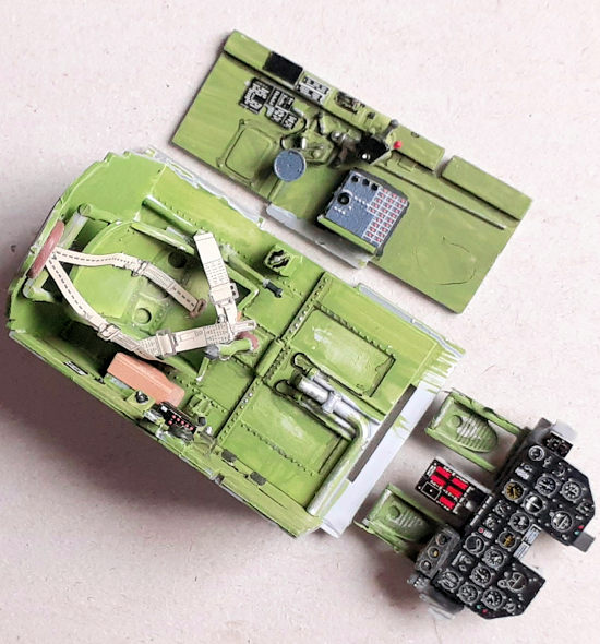 is
gets trapped between the fuselage halves. Test fitting revealed interference
between the front bulkhead and guide ridges on the interior of the halves. These
were ground off and the gap between halves was eliminated.
is
gets trapped between the fuselage halves. Test fitting revealed interference
between the front bulkhead and guide ridges on the interior of the halves. These
were ground off and the gap between halves was eliminated.
If a center line drop tank is going to be included on the finished model, internal structure must be added and flashed over holes cleared before mating the halves. The one photo that I was able to find of the subject of this build showed it without a tank installed, so I skipped that work called for in step two. After the exhaust vents are installed, the halves come together and the seam cleaned up.
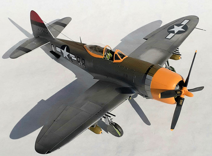
The turbocharger vents are added next. Every photo I’ve seen and also on every airframe that I’ve seen on display show the vents open when on the ground, so I used that option.
Interlocking tabs are a feature of the stabilizers/elevators. I don’t know what problem the tabs solve, but they created a problem by forcing either a dihedral in the tail planes, or tilt with the left side down and the right one up. No matter how much liquid cement I used, I couldn’t get the tail to line up properly. I pulled stabilizers off, leaving a gooey mess, cut off the tabs, and left plastic to harden overnight. Fortunately, cleaning up the joints and re-gluing them was easier than I thought it would be.
Before moving on to the next step of wing assembly, I noticed, when checking the alignment of the tail against the grid on my desk, that the tip of rear (main) right spar was higher than the left spar, meaning that the dihedral was off. About an 1/8th inch of material was removed from the top surface with a rotary tool quickly restored the symmetry.
To assemble the wings, attention must be paid as to which version is being modeled, since the location of underwing light varies, driving which panels are installed. The wheel wells build up conventionally. The left wing mated to the fuselage without any fuss, but achieving the correct dihedral with the right wing left a gap at the topside root that needed filling and sanding.
Engine assembly is called for in the next step. The
parts go together easily, but I made it more difficult for myself by adding
ignition wires. Using copper strands from a dead extension cord, I bent nine
pieces in half to make nine pairs and glued those to the back si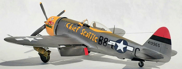 de
of reduction gear housing/harness part and glued that part to the cylinders.
Turns out, you can’t see them unless you’re looking for them. One very nice
detail in the kit is the P&W logo decal to apply to the front.
de
of reduction gear housing/harness part and glued that part to the cylinders.
Turns out, you can’t see them unless you’re looking for them. One very nice
detail in the kit is the P&W logo decal to apply to the front.
The instructions call for assembling the cowl panes around the engine, then attach the piece with cowl flaps (either opened or closed) to the fuselage, then attach the engine assembly. I’m not skilled enough to do it that way. Choosing the open flaps option, I cut away the material between the flaps to make them individual pieces. Returning to the engine, it was glued to the lower cowl panel. The upper panel came next, followed by the part with the flaps. This sequence made it easy to align the side panels and create good seams, although I spent over an hour cleaning them up. It also made it easy to paint the cowl without masking the fuselage. Unfortunately, the test fit revealed that a LOT of material needed to be removed from the mounting stub on the nose of the fuselage and the backside of the engine to get everything attach properly.
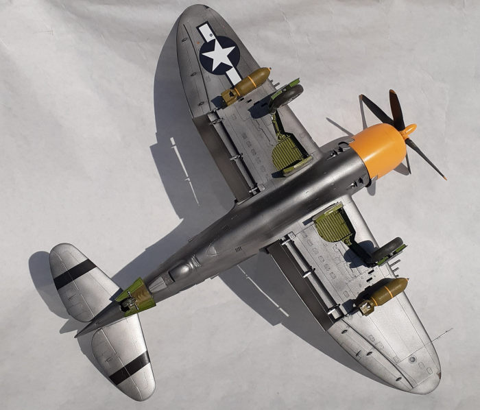
I skipped the next two landing gear assembly steps and installed the turbocharger and bomb hardpoints. The hardpoints required clamps to get a good fit. I left the tail wheel assembly for attaching after painting. The flaps were assembled and again, left off for post paint installing. Turning to the prop, I discovered that the blades for the Hamilton Standard option used on Gabresky’s plane were deleted from the sprue. One could whittle down the other blades to get the proper shape. Next the landing gear doors were prepared for painting.
| COLORS & MARKINGS |
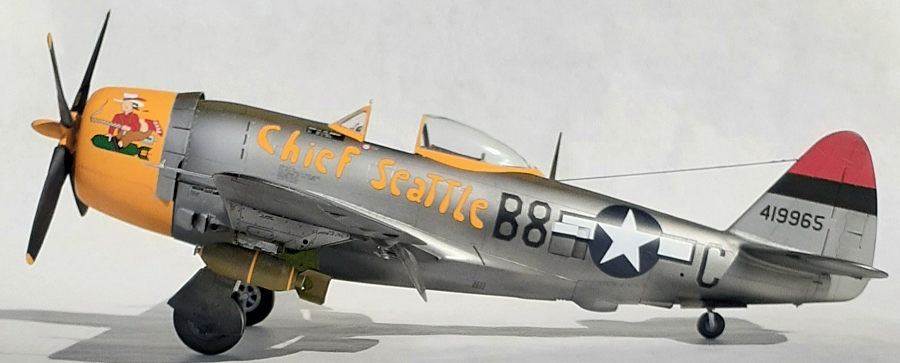
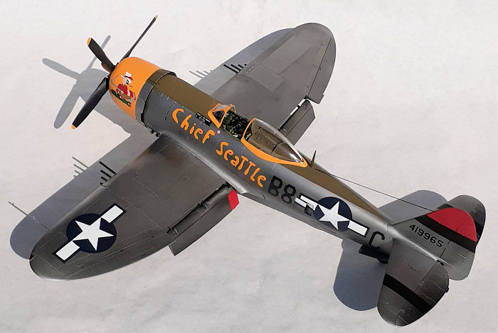
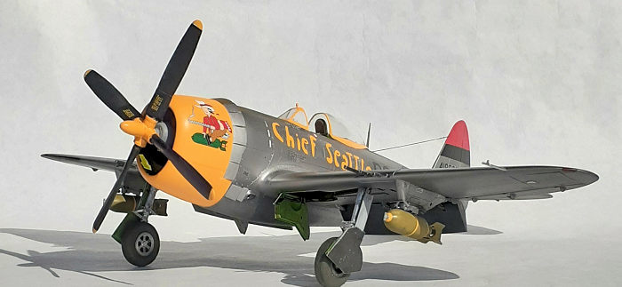
Having lived most of my life in the scenic Puget Sound basin, I felt compelled to use decals from EagleCals sheet EC32-104 that includes Lt. Murphy’s mount in the livery of 'Chief Seattle', flown in early 1945 around Bastogne.
First up was to mask the wind shield, canopy, cowl
flaps. and engine in order to apply deep yellow on those parts plus the cowl,
and prop hub. While that was curing, the cockpit was stuffed with some foam
packing material, then the olive drab anti-glare panel was sprayed on. The next
day the olive drab was masked along
 with the
landing gear wells and Alclad II gloss base was sprayed over the entire
airframe, including the still separate flaps and landing gear doors. As a
time-filling activity, the bombs were assembled, painted and decaled. The
stripes from the decal sheet are a nice touch and worked very well.
with the
landing gear wells and Alclad II gloss base was sprayed over the entire
airframe, including the still separate flaps and landing gear doors. As a
time-filling activity, the bombs were assembled, painted and decaled. The
stripes from the decal sheet are a nice touch and worked very well.
Masks were applied for the ID stripes on the tail surfaces and a coat of Airframe Aluminum sprayed over everything and some Steel around various panel edges. Some touch-ups were attended to and those areas re-sprayed. Various panels were masked around, including the gun bay access panels and Duraluminum was sprayed in those areas. Small access panels were given a dark wash. The cowl was masked and the flaps painted Aluminum, later the olive drab was painted on the upper flaps. The tip of the fin/rudder was masked and painted red.
All of the masking tape was removed and the decals applied. I’ve found that EagleCals decals are very good. In this set, the blue surround of the stars is the correct shade versus the kit decals which are too light. Unfortunately, I found the separate decals for the bars on the vents to be too long and need trimming before wetting. Several times, my ham fists allowed the decals to wrap around the backing as I applied them, but they are strong enough to unwrap. Micro Sol was very helpful with the compound curve of the cowl.
After the decals dried, a coat of acrylic satin plus a few drops of gloss varnish was sprayed over everything to create a more uniform finish.
| FINAL CONSTRUCTION |
A landing gear light was scavenged from the parts stash and painted first with chrome, then yellow. After a notch was filed into the top of the windshield, the light was glued in place and became a rearview mirror. Later I found two different styles of mirror, but they are not mentioned in the instructions and the windshield in this kit was not molded to accept either one.
 Placing the
model up-side-down in a cradle, the tail wheel and doors were installed,
followed by the flaps. The main landing gear was next. The instructions call for
the upper leg door to be attached to the leg. I couldn’t figure out how and
instead relied on the locating pins that mate with slots in the wing. Attaching
the bombs completed the underside.
Placing the
model up-side-down in a cradle, the tail wheel and doors were installed,
followed by the flaps. The main landing gear was next. The instructions call for
the upper leg door to be attached to the leg. I couldn’t figure out how and
instead relied on the locating pins that mate with slots in the wing. Attaching
the bombs completed the underside.
After setting the model on its wheels, work started at the tail and moved forward. The radio mast was installed and the aerial, made from .015” music wire, added. The canopy followed, being held in place with epoxy. The gunsight and windshield became an exercise in concentration. The big moment arrived with the addition of the engine/cowl sub-assembly. This also was attached with epoxy. Guns and pitot were glued in place and the finishing touch was the propeller.
| CONCLUSIONS |
I was surprised to encounter as many fit issues as I did. Fortunately, I overcame them easily. I am glad that I used the aftermarket parts and decals to create more interest and have the correct color for the insignia. Gun barrels and wheels might be good parts to buy also. As it is, it’s an eyecatcher. A fin fillet came with this kit, so a -N version can be built. The fit issues forced me to spend more time than I usually do with over 30 hours on this project.
6 April 2021 Copyright ModelingMadness.com If you would like your product reviewed fairly and
fairly quickly, please
contact
the editor
or see other details in the
Note to
Contributors.