| KIT #: | 81732 |
| PRICE: | $56.00 |
| DECALS: | Two options |
| REVIEWER: | John Summerford |
| NOTES: | Aero Master set 48-035 (OOP) decals used |
| HISTORY |
This information is courtesy of Wikipedia.
The Northrop P-61 Black Widow, named for the North American spider, was the first operational U.S. warplane designed as a night fighter, and the first aircraft designed to use radar. The P-61 had a crew of three: pilot, gunner, and radar operator. It was armed with four 20 mm (.79 in) Hispano M2 forward-firing cannon mounted in the lower fuselage, and four .50 in (12.7 mm) M2 Browning machine guns mounted in a remote-controlled dorsal gun turret.
It was an all-metal, twin-engine, twin-boom design developed during World War II. The first test flight was made on May 26, 1942, with the first production aircraft rolling off the assembly line in October 1943. The last aircraft was retired from government service in 1954.
Although not produced in the large numbers of its contemporaries, the Black Widow was effectively operated as a night-fighter by United States Army Air Forces squadrons in the European Theater, Pacific Theater, China Burma India Theater, and Mediterranean Theater during World War II. It replaced earlier British-designed night-fighter aircraft that had been updated to incorporate radar when it became available. After the war, the P-61—redesignated the F-61—served in the United States Air Force as a long-range, all-weather, day/night interceptor for Air Defense Command until 1948, and Fifth Air Force until 1950.
 On the
night of 14 August 1945, a P-61B of the 548th Night Fight Squadron named Lady in
the Dark was unofficially credited with the last Allied air victory before VJ
Day. The P-61 was also modified to create the F-15 Reporter photo-reconnaissance
aircraft for the United States Army Air Forces and subsequently used by the
United States Air Force.
On the
night of 14 August 1945, a P-61B of the 548th Night Fight Squadron named Lady in
the Dark was unofficially credited with the last Allied air victory before VJ
Day. The P-61 was also modified to create the F-15 Reporter photo-reconnaissance
aircraft for the United States Army Air Forces and subsequently used by the
United States Air Force.
P-61C
The P-61C was a high-performance variant designed to rectify some of the combat deficiencies encountered with the A and B variants. Work on the P-61C proceeded quite slowly at Northrop because of the higher priority of the Northrop XB-35 flying wing strategic bomber project. In fact, much of the work on the P-61C was farmed out to Goodyear, which had been a subcontractor for production of Black Widow components. It was not until early 1945 that the first production P-61C-1-NO rolled off the production lines. As promised, the performance was substantially improved in spite of a 2,000 lb (907 kg) increase in empty weight. Maximum speed was 430 mph (690 km/h) at 30,000 ft (9,000 m), service ceiling was 41,000 ft (12,500 m), and an altitude of 30,000 ft (9,000 m) could be attained in 14.6 minutes.
The P-61C was equipped with perforated fighter airbrakes located both below and above the wing surfaces. These were to provide a means of preventing the pilot from overshooting his target during an intercept. For added fuel capacity, the P-61C was equipped with four underwing pylons (two inboard of the nacelles, two outboard) which could carry four 310 gal (1,173 l) drop tanks. The first P-61C aircraft was accepted by the USAAF in July 1945. However, the war in the Pacific ended before any P-61Cs could see combat. The 41st and last P-61C-1-NO was accepted on 28 January 1946. At least 13 more were completed by Northrop, but were scrapped before they could be delivered to the USAAF.
Project Thunderstorm
Excerpted from Historynet.com ( https://www.historynet.com/project-thunderstorm.htm )
The Thunderstorm Project’s main objective was to get inside a severe weather event to assess its characteristics and the dangers it held. Central Florida, the frequent site of violent thunderstorms, became a logical place for the storm study to begin in the summer of 1946. The airmen participating in the program were based at Pinecastle Army Airfield near Orlando. The following summer the project was moved to Wilmington, Ohio, and headquartered at the All-Weather Flying Center at Clinton County Army Air Force Base.
It was an important study for its time, on a par with postwar atomic bomb testing then taking place in the South Pacific. The aircraft chosen for the project, surplus Northrop P-61C Black Widows, flew as many missions through thunderstorms as possible during different phases of severe weather events. The P-61Cs would enter the storm at different altitudes in a vertical stack, 5,000 feet apart, to obtain the broadest spectrum of measurements possible.
 It was
dangerous flying, with few dull moments. Roscoe R. Braham Jr., a senior analyst
with the Thunderstorm Project, said the goal was “to obtain the maximum number
of traverses through each storm and to sample storms in all stages of
development. No storm was to be avoided because it appeared too large or
violent.”
It was
dangerous flying, with few dull moments. Roscoe R. Braham Jr., a senior analyst
with the Thunderstorm Project, said the goal was “to obtain the maximum number
of traverses through each storm and to sample storms in all stages of
development. No storm was to be avoided because it appeared too large or
violent.”
Each Black Widow carried a crew of three: an accomplished instrument pilot, a highly trained radar operator and a weather observer. The military pilots were members of Air Materiel Command’s All-Weather Flying Division, and underwent careful screening to ensure they were well suited to the program. In addition to their volunteer spirit, the crews had to project a high level of alertness and confidence and be unfazed by the unexpected dangers of such hazardous research.
These particular Black Widows were obtained from a weather reconnaissance outfit being terminated in Alaska, the Cold Weather Testing Detachment, Unit 616, based at Ladd Army Airfield near Fairbanks. The twin-engine P-61 was chosen for the study largely because of its sturdy construction, durability and onboard radar. NACA engineers equipped the Black Widows with instruments to measure their response to turbulence, and installed transponders so they could be tracked. In effect, the entire airplane was a storm turbulence sensor.
Pilots were instructed to set the airplane trim for straight and level flight prior to entering a thunderstorm, and to exert minimal control input once they had penetrated the storm. Power settings and control surface movements were constantly recorded, and instrument panels filmed. Considering the severe conditions inside the thunderclouds, and the P-61s’ dramatic reactions to violent updrafts and downdrafts, getting usable film footage was not easy. Motion picture film of a Black Widow’s instrument panel as it flew through a storm cell showed the needles on the horizon and altimeter gauges jumping all over the place.
As might be expected, the P-61s took a beating. One Black Widow was upended onto its back during a mission, but the pilot managed to recover. Another pilot issued a radio report of heavy, blinding snow inside a storm cloud. Several aircraft were struck by lightning, hail and ice. P-61 nose cones were punched in by the weather and propellers were bent and dented. In spite of such punishment, there were no accidents or fatalities during the project, which encompassed 1,362 cloud penetration flights.
About 180 hard-working men and women participated in the Thunderstorm Project from 1946 to 1949, helping to greatly advance the science of meteorology. Today’s understanding of thunderstorms owes much to their efforts, and aviation is far safer for it. Data collected during the project showed that even light aircraft can structurally withstand the wrath of storms, and that with proper instrumentation and training a pilot could minimize the risk of encountering turbulence and strong vertical motion.
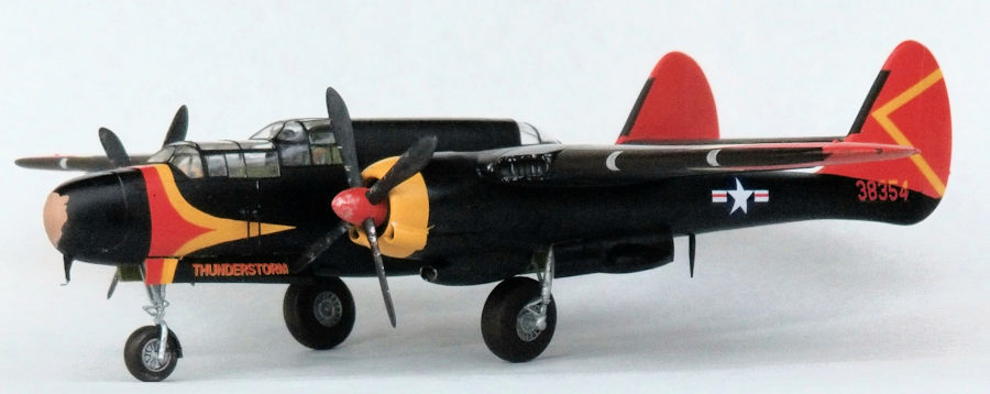
Ever since I read about Project Thunderstorm, I’ve wanted to build a plane dinged up after a mission. I was held back by trying to decide how to portray the two-color ID number on the boom. As noted in a recent review, I had difficulties with decals from Iliad Design. Bob Migliardi, of Iliad, contacted me to see if he could compensate me for the issues that I had. With his help, I was able to track down a set of decals for this project. Thank You Bob!
| THE KIT |
 Inside a
sturdy cardboard box are nine sprues of gray plastic, all but two individually
bagged. A sprue of clear parts is wrapped in foam and bagged with the nose
individually wrapped. The cowls are also separately bagged. The last parts are
cast metal that are used as ballast weights. Detail is crisp with the panel
lines being restrained recesses and the raised detail is appropriate.
Inside a
sturdy cardboard box are nine sprues of gray plastic, all but two individually
bagged. A sprue of clear parts is wrapped in foam and bagged with the nose
individually wrapped. The cowls are also separately bagged. The last parts are
cast metal that are used as ballast weights. Detail is crisp with the panel
lines being restrained recesses and the raised detail is appropriate.
A 16-page instruction booklet includes a parts map with footnotes about unused items. Assembly is divided into 18 steps. Sub-assemblies are broken down into fuselage, booms with landing gear down, wings, engine nacelles, and stabilizer/elevator. A color sheet (which is optimistic being as, like the Model T, the only color is black) illustrates decal placement. Paint colors are referenced to Mr. Hobby, Vallejo, Model Master, Tamiya and Humbrol brands.
| CONSTRUCTION |
Before opening bags of sprues, I checked the landing gear struts and wheel bays and doors to see if it was possible to install the gear after assembling the airframe. That looked to be the case, so started on the cockpit. The floors, bulkheads, and wheel bay doors were given a coat of white primer and then sprayed with acrylic zinc chromate thinned with rubbing alcohol. Once the paint was dry, a dark wash was applied on all of the recesses. The black boxes and instrument panel were painted next and then dusted with a light pigment to bring out the highlights. The front cockpit went together easily. The nose wheel bay attaches to the bottom of the cockpit along with two metal weights. I saved the landing gear for later.
Before gluing the cockpit side panels to the fuselage halves, I blanked off the gun ports, since all of the armament was removed. The side panels dropped into place. The aft station was assembled and laid in place in one fuselage half while the glue cured to make sure the alignment was correct. A test fit revealed that some filing of the floor of was required to get the halves to mate. When that looked good, that station was glued in place. The cockpit was laid in place to check its alignment and I discovered that I need to remove material from the front weight, something I was loathed to do. I also figured out that bottom leg of the “L” guide for the instrument panel molded on the right fuselage half need to be removed for the nose to form up correctly. With that done, the cockpit was glued in place and the halves mated together.
 Several
hours were spent masking the clear parts. (Now I remember why I haven’t built a
Dornier DO-17.) Once done, the fuselages clear pieces were glued in place and
all the seams cleaned up. The instructions call for the radar and its nose dome
to be installed next. I decided to wait to see if some ballast need to added.
Several
hours were spent masking the clear parts. (Now I remember why I haven’t built a
Dornier DO-17.) Once done, the fuselages clear pieces were glued in place and
all the seams cleaned up. The instructions call for the radar and its nose dome
to be installed next. I decided to wait to see if some ballast need to added.
The next four steps call for assembling the right boom/wing. I skipped adding the landing gear for later. I found that everything went together easily with little in the way of seam clean up. I am disappointed at the fit of the wing light lenses; they are way too thick. I painted their recesses silver and glued them in place. After grinding them flush with the leading edge and polishing them, I decided to delete them and fabricate new lights.
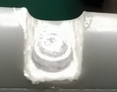 That
meant sawing, grinding, and filing notches in the leading edges of the wings.
Voids in the notches were filled with putty, then flat white paint brushed on.
Using a punch and die set, I made appropriate size “lamps” from .020 sheet and
painted them chrome. The “lamps” were glued into place with super glue and the
lenses built up from several layers of the glue. The final layer was applied
with the leading edge pointing down so that the surface tension of the glue
mimicked the shape of the edge. Some filing, sanding and buffing finished the
procedure.
That
meant sawing, grinding, and filing notches in the leading edges of the wings.
Voids in the notches were filled with putty, then flat white paint brushed on.
Using a punch and die set, I made appropriate size “lamps” from .020 sheet and
painted them chrome. The “lamps” were glued into place with super glue and the
lenses built up from several layers of the glue. The final layer was applied
with the leading edge pointing down so that the surface tension of the glue
mimicked the shape of the edge. Some filing, sanding and buffing finished the
procedure.
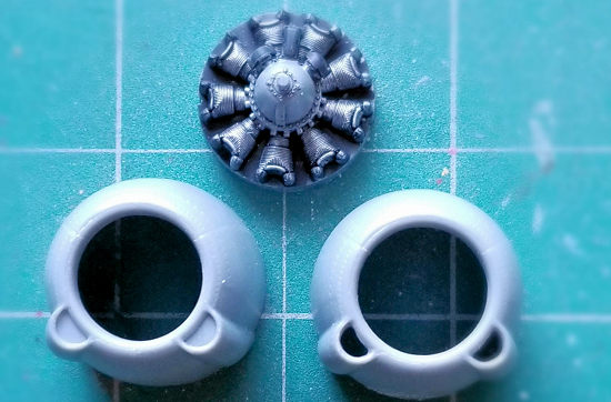 Before attaching the
engine/cowl duo, I opened the intakes in the cowls. While I was at it, used my
thinnest saw and cut between the cowl flaps to separate them and also thinned
the trailing edges.
Before attaching the
engine/cowl duo, I opened the intakes in the cowls. While I was at it, used my
thinnest saw and cut between the cowl flaps to separate them and also thinned
the trailing edges.
Experience gained from assembling the right boom/wing made putting together the left side go much faster. Using a couple of mini bar-clamps with a stand, plus a little bit of filing and fussing, all of the major components were brought together and glued with liquid cement. After curing overnight, the seams were given some filler and cleaned up. I was concerned that the ballast was insufficient, but I found that the model is indeed nose heavy without needing more weight up front.
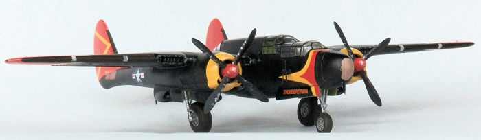
A test fit of the nose piece revealed that either it was too small, or the fuselage too big. I think the problem is the fit of nose gear bay forces the fuselage too wide and the weight attaches too low. I shaved a lot of material off of the bottom of the nose weight to get the piece to fit flush with the top of the fuselage. In order to get the sides flush, I split the bottom of the nose piece and wedged in a spreader bar made from scrap sprue. I’m pleased how well this worked. A backing plate was glued in behind the cut and the gap was filled in and smoothed over. I also added a bit of lead to compensate for the metal lost. Before moving on to the paint booth, the prop spinners were gouged with several different sized rotary bits to show the dents they suffered.
| COLORS & MARKINGS |
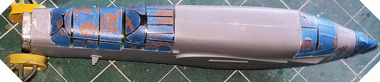
 The nose, wing
tips, and tail were sprayed with primer. The nose received a coat of light tan
and masked with a bit of oval of tape and the edges stippled with liquid mask to
simulate the paint abraded by hail. The rest of the nose plus the cowls and tail
were sprayed chrome yellow.
The nose, wing
tips, and tail were sprayed with primer. The nose received a coat of light tan
and masked with a bit of oval of tape and the edges stippled with liquid mask to
simulate the paint abraded by hail. The rest of the nose plus the cowls and tail
were sprayed chrome yellow.
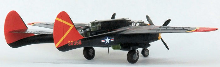
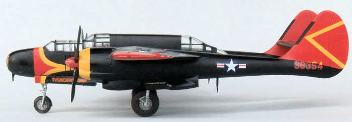
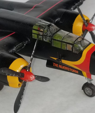
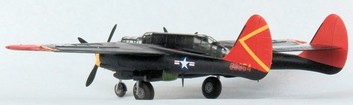
The Aero Master decals have the fin/rudder and ID as one piece. I’m not a fan of this kind of arrangement because my experience is that the hinge line looks awkward and there is usually something that has to be trimmed. I opted to cut out the ID number and paint the fins and rudders and use the yellow trim supplied for the wings. The yellow stripes for the nose don’t extend over the top, so that area was also painted and masked. Aero Master supply the mask outlines needed in this area plus the wing tips. Italian red was sprayed on the prop spinners, nose, wing tips, and tails, then masked for the gloss black. Several sessions were required to get a smooth gloss black. Flat black was sprayed on the wing tops to represent exhaust staining. The de-icing boots were masked and sprayed a rubber color.
All of the masks were removed prior to decaling. I used the stars and bars and ID number from the Aero Master sheet. The yellow trim for the wing tips was a disappointment in that they were not opaque enough. I should have used the masks in these areas too. the decals responded well to Micro Sol. The only decals that I used from the kit were the wing walk markings. They are printed as single piece “U” shapes. After wrestling the first “U” into place, I cut the other one into three legs and had a much easier time.
After the decals dried, I rubbed over the exhaust stains with dark gray and dark brown powder with a cotton swab. It’s a subtle effect. Aluminum color was stippled on the prop blades and spinners, plus the leading edges of wings, fins, and fuel tanks to simulate paint chipping.
I set the model upside down in a cradle to finish the build. I discovered that getting the main gear legs into their bays was not a simple as I thought it would be. I had to remove locating ears on the legs to get them into place. I reinforced the joins with super glue. The doors came next and they attach nicely. The props were next followed by the antennas located below the cockpit. The last item glued on was the pitot on the nose.
| CONCLUSIONS |
 It seemed like this build was a lot of starting and
stopping waiting for either paint or glue to cure. I spent well over 30 hours on
the project. After setting the model on the wheels, I think it is worth getting
metal replacement legs from Scale Aircraft Conversions (Set # 48293). The size
of the model (16” wingspan) slows the process down. The parts fit well, save for
the nose and lenses, and I used little filler.
It seemed like this build was a lot of starting and
stopping waiting for either paint or glue to cure. I spent well over 30 hours on
the project. After setting the model on the wheels, I think it is worth getting
metal replacement legs from Scale Aircraft Conversions (Set # 48293). The size
of the model (16” wingspan) slows the process down. The parts fit well, save for
the nose and lenses, and I used little filler.
13 March 2020
Copyright Modeling Madness.com
If you would like your product reviewed fairly and fairly quickly, please contact the editor or see other details in the Note to Contributors.
Back to the Main Page Back to the Review Index Page Back to the Previews Index Page