Valom 1/72 P-75A Eagle
| KIT #: | 72010 |
| PRICE: | $21.95 |
| DECALS: | One option |
| REVIEWER: | Mark Joyce |
| NOTES: | Short run |
| HISTORY |
 The General
Motors/Fisher P-75 Eagle was a fighter aircraft designed by the Fisher Body
Division of General Motors. Development started in September 1942 in response to
a United States Air Army Force’s requirement for a fighter possessing an
extremely high rate of climb, using the most powerful liquid-cooled engine then
available, the Allision V-3420, which was effectively two V-1710 units mated to
a common crankcase. The first XP-75 prototype flew on 17 November 1943, but due
to development problems, delays, and cost overruns only 13 XP-75s and production
P-75As were completed before the program was cancelled.
The General
Motors/Fisher P-75 Eagle was a fighter aircraft designed by the Fisher Body
Division of General Motors. Development started in September 1942 in response to
a United States Air Army Force’s requirement for a fighter possessing an
extremely high rate of climb, using the most powerful liquid-cooled engine then
available, the Allision V-3420, which was effectively two V-1710 units mated to
a common crankcase. The first XP-75 prototype flew on 17 November 1943, but due
to development problems, delays, and cost overruns only 13 XP-75s and production
P-75As were completed before the program was cancelled.
| THE KIT |
See Scott Van Aken’s review of the kit here.
| CONSTRUCTION |
I became interested in this airplane after reading the book “American Secret Projects” by Tony Buttler and Alan Griffith (some of you might recognize Alan’s name from his association with the now defunct model company AMtech, which produced some of my favorite P-40 kits, but that’s another story). Deciding I was interested enough at this point I wanted a model of the XP-75, I discovered Valom released a few different boxings for this airplane in 72nd scale and, after deciding that the natural metal P-75A was the most attractive, it was off to eBay to find a kit. Not only my first P-75, but my first Valom kit!
Construction started, as is
the usual procedure, with the cockpit. This is something of a curate’s egg:
Although the kit includes nice photo-etch seatbelts, rudder pedals, and an
instrument panel (but no gunsight), along with an acetate film for the di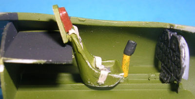 als,
the control stick is so large for the scale that Captain America couldn’t budge
it and there is absolutely no detailing for the sidewalls or the area behind the
seat. I wanted this build to be “out of the box,” but those modelers who wish to
scratch-build some details (and with the clear but thick bubble canopy, there’s
a lot of scratch-building that can occur), the National Museum of the Air Force
has some excellent photographs on its website of its beautifully restored P-75A.
als,
the control stick is so large for the scale that Captain America couldn’t budge
it and there is absolutely no detailing for the sidewalls or the area behind the
seat. I wanted this build to be “out of the box,” but those modelers who wish to
scratch-build some details (and with the clear but thick bubble canopy, there’s
a lot of scratch-building that can occur), the National Museum of the Air Force
has some excellent photographs on its website of its beautifully restored P-75A.
I discovered that, no matter how I positioned the cockpit floor, the instrument panel was just too tall to fit properly. Ultimately, I figured the pilot really didn’t need those bottom instruments so simply cut off the bottom portion and crammed the rudder panels underneath. I also was perturbed by the open chasm behind the seat, so used some sheet styrene to simulate an instrument deck of sorts. So much for “out of the box!” I decided that the Model Master enamel Interior Green I had on hand was a good enough color for the cockpit and liberally airbrushed some on. A little yellow to the grip on the control stick to match the restored one Air Force Museum added a colorful, if probably historically inaccurate, touch.
 Once the interior was more
or less done, I glued the fuselage halves together and fortunately remembered to
install the “donuts” to hold the spinner in place at this time. No locating pins
on this kit, which is not necessarily a bad thing. I found that the fit of the
halves was pretty good, although as in the case with almost all my builds I had
to break out the sanding sticks to level things out before I used some
gap-filling super glue to (intentionally) get rid of the seam lines and
(unintentionally) some of the engraved panel lines. Around this time I noticed
that some of the panel lines on one side of the fuselage weren’t always the same
size as the corresponding ones on the other side, which made rescribing a rather
interesting endeavor considering it’s not my strong point under the best of
circumstances.
Once the interior was more
or less done, I glued the fuselage halves together and fortunately remembered to
install the “donuts” to hold the spinner in place at this time. No locating pins
on this kit, which is not necessarily a bad thing. I found that the fit of the
halves was pretty good, although as in the case with almost all my builds I had
to break out the sanding sticks to level things out before I used some
gap-filling super glue to (intentionally) get rid of the seam lines and
(unintentionally) some of the engraved panel lines. Around this time I noticed
that some of the panel lines on one side of the fuselage weren’t always the same
size as the corresponding ones on the other side, which made rescribing a rather
interesting endeavor considering it’s not my strong point under the best of
circumstances.
I then moved on to the wings and glued the tops to the bottom. Again, fit was decent considering my modeling skills and, breaking out the sanding sticks and gap-filling glue once more, whipped them into shape. Perhaps it was the wrong shape, for when I test fitted the resin housings for the landing gears found that the fit was horrible. No matter how much I sanded, cursed, filed, cursed, sanded some more, cursed a lot more, I ended up with some rather large gaps. But, hey, that’s why they call it gap-filling superglue, so with a liberal application made things “good enough for government work!”
Next it was time to glue
the wings to the fuselage. I can’t say I was surprised to find there was a gap
between the upper portion of the wings and the fuselage. While scratching my
head about the best way to fix this, Modeling Madness came to my rescue and I
remembered how Tom Cleaver used a “spreader bar” on one his builds long ago.
Cutting a p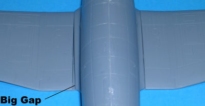 iece of plastic to what appeared to be the appropriate size, I
inserted it into the fuselage opening and, Presto, no more gap!
iece of plastic to what appeared to be the appropriate size, I
inserted it into the fuselage opening and, Presto, no more gap!
I moved on to the horizontal and vertical stabilizers. Remember, no locating pins on this kit! Fortunately I found the horizontal ones fit well, but I probably went through a couple of sanding sticks and more than a couple of curse words to get the vertical one to fit to my satisfaction. This is one area I vividly remember having to use quite a bit of Mr. Surfacer 500.
Valom took a rather simplified approach to the underside intake assembly, which I initially appreciated. This is a separate affair consisting of upper and lower halves, along with two photoetch intake screens that for the life of me I couldn’t tell whether or not existed on the real airplane, but since the only option is to have a couple of gaping holes I decided to install them. There’s a nice big opening in the fuselage where the completed intake assembly is fitted, but this is where I had second thoughts about the simplistic engineering. Instead of sticking directly forward like it should, my assembly had a pronounced downward sweep, which would make a wheels-up landing interesting to say the least. Worse of all from an accuracy issue is there is a noticeable gap between the sides of the intake assembly and the fuselage that didn’t exist on the real P-75A. Perhaps it would have been better to mold the intake to the fuselage to prevent this gap, but I guess we will never know.
 My last
major hurdle before attachment of the “fiddly bits” was the canopy. Being a
bubble top, it was easy to mask with Tamiya tape, and once masked I airbrushed
Interior Green to replicate the interior framing (how some modelers can actually
mask the inside of the canopy for this
task is a mystery to me). Now that this was done, I used watch crystal clear
cement to attach the canopy to the fuselage. Needless to say, fit was less than
perfect but at this stage of the build I didn’t have the energy or desire to
sand it to fit, so just used Elmer’s white glue smoothed with a moistened finger
to fill whatever gaps existed.
My last
major hurdle before attachment of the “fiddly bits” was the canopy. Being a
bubble top, it was easy to mask with Tamiya tape, and once masked I airbrushed
Interior Green to replicate the interior framing (how some modelers can actually
mask the inside of the canopy for this
task is a mystery to me). Now that this was done, I used watch crystal clear
cement to attach the canopy to the fuselage. Needless to say, fit was less than
perfect but at this stage of the build I didn’t have the energy or desire to
sand it to fit, so just used Elmer’s white glue smoothed with a moistened finger
to fill whatever gaps existed.
Working with the “fiddly bits” was generally not newsworthy, although constructing the truly fiddly landing gear was somewhat of a chore. I ultimately accomplished this by temporarily attaching the main gear in place so that I could securely glue the side braces at the proper angle and paint the entire assembly afterwards.
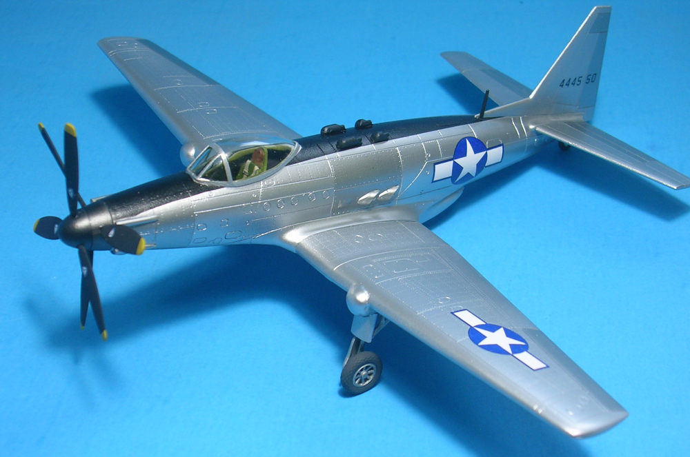
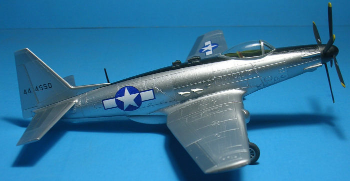
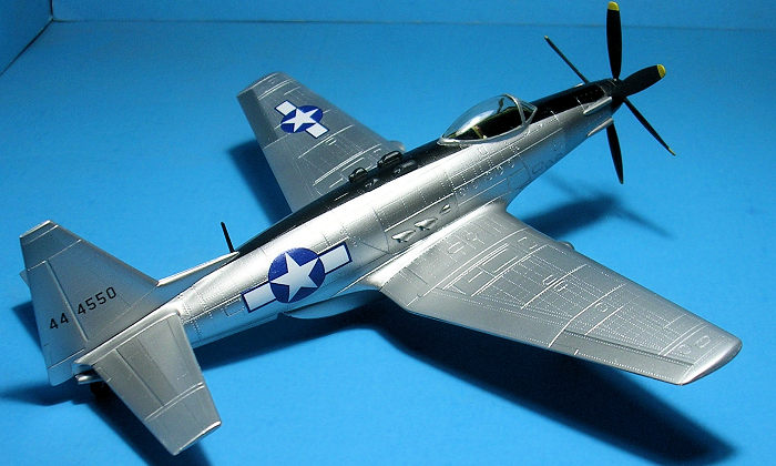
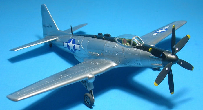
| COLORS & MARKINGS |
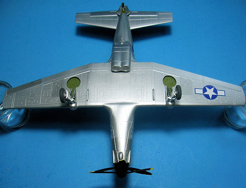 Now off to
the paint shop. Priming the airframe with Alclad II Gray Primer & Microfiller
showed surprisingly (for me) few flaws and touch-ups that needed to occur. Once
these repairs were accomplished, I airbrushed a main coat of Alclad II Aluminum
on the airframe, then masked off select panels for different shades utilizing
Dark Aluminum, Duraluminum, and Steel, with the final main task of masking and
airbrushing black for the anti-glare strip on top of the fuselage. Easy-Peasy.
The instructions have you paint the navigation lights and machine gun barrels on
the wings, but either my kit didn’t have any of them or they disappeared in the
feverish sanding I did. No worries about those barrels, since that lack of a
gunsite would have made their accuracy debatable. I also passed on making my own
pitot tube, which the instructions have you do. Who really needs to know how
fast they are going anyway?
Now off to
the paint shop. Priming the airframe with Alclad II Gray Primer & Microfiller
showed surprisingly (for me) few flaws and touch-ups that needed to occur. Once
these repairs were accomplished, I airbrushed a main coat of Alclad II Aluminum
on the airframe, then masked off select panels for different shades utilizing
Dark Aluminum, Duraluminum, and Steel, with the final main task of masking and
airbrushing black for the anti-glare strip on top of the fuselage. Easy-Peasy.
The instructions have you paint the navigation lights and machine gun barrels on
the wings, but either my kit didn’t have any of them or they disappeared in the
feverish sanding I did. No worries about those barrels, since that lack of a
gunsite would have made their accuracy debatable. I also passed on making my own
pitot tube, which the instructions have you do. Who really needs to know how
fast they are going anyway?
What few decals are necessary went on very nicely and I only wish all kit ones laid down as well.
| CONCLUSIONS |
So, besides the fact I noticed in the photographs that some of the propeller blades stick out at odd angles like a half-opened umbrella, which there’s always tomorrow to fix, I’m pretty satisfied with how the end result looks. I found some other builds of this kit while searching the Internet, all of which are nicer than mine, so obviously most of the issues I had (and there really weren’t too many) were operator-error. As most things in the modeling world, your mileage may vary. And, anyways, it’s only a model!
| REFERNCES |
Butler, Tony, and Alan Griffith. American Secret Projects: Fighters, Bombers, and Attack Aircraft 1937-1945. Manchester: Crecy Publishing Ltd., 2015.
National Museum of the US Air Force: http://www.nationalmuseum.af.mil/Visit/Museum-Exhibits/Fact-Sheets/Display/Article/195783/fisher-p-75a-eagle/
Wikipedia: https://en.wikipedia.org/wiki/Fisher_P-75_Eagle
14 May 2018
Copyright ModelingMadness.com
If you would like your product reviewed fairly and fairly quickly, please contact the editor or see other details in the Note to Contributors.
Back to the Main Page Back to the Review Index Page Back to the Previews Index Page