GWH 1/48 P-61B Black Widow
| KIT #: | L4810 |
| PRICE: | $85.00 or so |
| DECALS: | Two options |
| REVIEWER: | Rob Hart |
| NOTES: | Quickboost QB 48-470 P-61A/B Propellers, Kelik K48058 P-61B interior 3D decals, Eduard 648057 P-61 Wheels, Master AM-48-001 Browning M2 Aircraft .50 Caliber Barrels, and Eduard EX450 P-61B mask set |
| HISTORY |
The P-61B was the most produced variant of the P-61 family. The crew nacelle on the P-61B was extended 8” longer than the P-61A's crew nacelle to accommodate an access panel at the rear of the radome. The P-61B also had an upgraded interception radar, a tail warning radar, night vision binoculars, and an improved crew heating system. Unfortunately, the P-61B did not address the low climb rate, relatively slow top speed, and short endurance of the P-61A. Despite their shortcomings, P-61s shot down 128 enemy aircraft in WWII and a P-61B is unofficially credited with scoring the last aerial victory of the war.
 A tribute
model:
A tribute
model:
I built this model as a tribute to my late father-in-law, Lowell Nash. Lowell was a P-61 ground crewman in WWII. My wife had told me that her father served in the military in WWII, but she didn't know any details about his service. After Lowell's wife died, he began staying with us a couple of times a year for a few weeks at a time. During one of these visits, I came home from work to find Lowell browsing through one of my books about the P-61. He told me that he had been a P-61 ground crewman in WWII. I had a lot of questions, but Lowell knew surprisingly little about the P-61. In fact, the first time that he had heard about the P-61 being used in combat was when he read it in my book! Lowell had spent most of his time in the service at a stateside training base near Fresno, California. The war ended before he could be deployed overseas. I asked Lowell if he would like for me to build him a model of a P-61, but he declined my offer. After he left to go home, I bought every book about the P-61 that I could find in preparation for his next visit. In a recent conversation with my wife, the subjects of Lowell's military service and the airplane that he worked on came up. After I showed her a photo of the P-61, she asked me to build a model of one.
| THE KIT |
Here's a link to Scott Van Aken's preview of the kit.
| CONSTRUCTION |
I started construction with the crew compartments. I scraped, filed, chiseled, and sanded off most of the raised details in anticipation of using the Kelik 3D printed decals. The decals fit well and I attached them with white glue. I had previously painted the visible surfaces of the crew compartments Interactive Real Colors Interior Green and the rest of the fuselage interior with Tamiya XF-4 Yellow Green. I managed to break two of the crew seat's frames when I tried to remove them from the sprues. Repairing them was a fiddly job that I had to repeat when I was attaching them to the floor. I also broke the pilot and gunner's access ladder, but it only had to be repaired once. The pilot's gunsight went MIA and I replaced it with a resin one from my spares collection. The rest of the crew compartment construction went off without issue. The kit includes the well for the internal parts of the dorsal turret, but it can't be seen after the fuselage is closed and adds an unnecessary level of complexity. I included it in my model, but if I build the kit again I'll leave it out. Before the fuselage could be closed the nose landing gear bay and leg needed to be trapped inside the fuselage. I did not glue the leg in the down position so that it could be folded back into the bay until the final assembly stages. The cannon bay also needed to be assembled and glued into position before joining the fuselage halves. The kit provides a quartet of nicely detailed 20 MM cannons and their mounts, but nothing else to go in the bay. The kit provides the option of posing the cannon bay doors open, but I wasn't up to adding all the details that would be visible in the open bay, so, after the fuselage was closed, I glued the doors in the closed position, filled the seams, sanded them smooth, and re-scribed the panel lines.
 The kit
provides a pair of nicely detailed engines with separate banks of cylinders,
induction pipes, push rod tubes, magnetos, and exhaust manifolds, Photo etched
brass ignition harnesses are also included, but I figured that they were
probably going to be more trouble than they were worth and opted to wire the
engines with small gauge copper wire. As it turned out, the engines sit so far
back in the cowlings that the wiring is not visible to the naked eye. In fact. I
wondered if the kit had the engines
The kit
provides a pair of nicely detailed engines with separate banks of cylinders,
induction pipes, push rod tubes, magnetos, and exhaust manifolds, Photo etched
brass ignition harnesses are also included, but I figured that they were
probably going to be more trouble than they were worth and opted to wire the
engines with small gauge copper wire. As it turned out, the engines sit so far
back in the cowlings that the wiring is not visible to the naked eye. In fact. I
wondered if the kit had the engines
positioned too far to the rear, because the crankcases looked too long. I decided to leave it alone as correcting it was going to be a major job and, after assembly, it wasn't that noticeable.
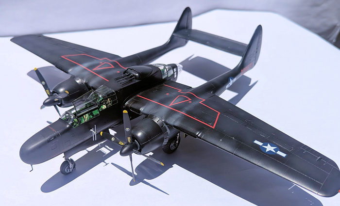
The tail booms are molded in vertically split halves and incorporate the vertical fins. Before the halves can be joined, the main landing gear bays need to be assembled and attached to the inside walls of the booms. The assembled bays are sloppy fits to the booms and careful assembly to ensure proper alignment paid dividends when it came time to attach the main landing gear legs. The instructions show the landing gear legs have to be trapped inside the bays before the booms are closed, but, with a little tinkering, the landing gear will go into the bays correctly aligned after the booms are assembled. Before joining the halves of the booms, I filled the forward interiors of the booms with as many lead fishing weights as the spaces available could accomodate. After the booms were closed, the seams were sanded smooth and the panel lines re-scribed. The boom assemblies were completed when large photo-etched grates were bent to shape and attached to the underside of the booms just aft of the engine cowlings.
With the major airframe sub-assemblies completed, I simultaneously attached the wings to the fuselage, the booms to the wings, and the horizontal stabilizer to the booms. All of the joints had large gaps and steps requiring seemingly endless filling, sanding, and re-scribing sessions. The worst offender of the ill fitting airframe parts was the horizontal stabilizer. It was thicker than the fillets molded on the sides of the booms necessitating sanding down the inner sides of the upper and lower halves of the stabilizer until its thickness matched that of the fillets. The process had to be repeated on the separately molded elevator. The kit provides all of the control surfaces as separate parts. I could not find a single photo of a P-61 with the control surfaces in any position other than neutral. To that end, I attached the ailerons, flaps, rudders, and spoilers in their neutral positions. Just for variety I attached the elevator deflected slightly down.
 Prior to
painting the model, I test fitted the fixed portions of the crew compartment's
clear parts to the fuselage. With the exception of the tail cone, they fit
poorly. This issue was compounded by GWH molding all of the canopies' emergency
exit hatches as separate parts. The crew of the P-61 entered and exited through
hatches in the bottom of the aircraft. Egress from the crew compartments through
the canopies' exit hatches only occurred when the aircraft had made a wheels up
landing or for maintenance. I compromised and left the exit hatch directly over
the pilot in the open position as photos supported that was a common occurrence.
I wasn't surprised to find that the emergency exit hatches did not fit the
canopies very well. I managed to get reasonable fits of the crew compartment's
clear parts to themselves and to the fuselage with a lot of tedious filling and
sanding. The canopy was also the source of the kit's most glaring inaccuracy.
The pilot's and gunner's windshields are exactly the same size on real P-61s.
The pilot's windshield on the kit's canopy is noticeably shorter than the
gunners windshield. The kit provides a multi-part representation of the the
SCR-720 radar, but I opted to leave it out and fill the radome with lead fishing
weights as I was concerned that the model might be a tail sitter. The radome was
also a sloppy fit to the fuselage and needed filler, sanding, and re-scribing.
With the airframe largely complete, I masked the clear parts and the landing
gear bays and headed for the spare bedroom paint shop.
Prior to
painting the model, I test fitted the fixed portions of the crew compartment's
clear parts to the fuselage. With the exception of the tail cone, they fit
poorly. This issue was compounded by GWH molding all of the canopies' emergency
exit hatches as separate parts. The crew of the P-61 entered and exited through
hatches in the bottom of the aircraft. Egress from the crew compartments through
the canopies' exit hatches only occurred when the aircraft had made a wheels up
landing or for maintenance. I compromised and left the exit hatch directly over
the pilot in the open position as photos supported that was a common occurrence.
I wasn't surprised to find that the emergency exit hatches did not fit the
canopies very well. I managed to get reasonable fits of the crew compartment's
clear parts to themselves and to the fuselage with a lot of tedious filling and
sanding. The canopy was also the source of the kit's most glaring inaccuracy.
The pilot's and gunner's windshields are exactly the same size on real P-61s.
The pilot's windshield on the kit's canopy is noticeably shorter than the
gunners windshield. The kit provides a multi-part representation of the the
SCR-720 radar, but I opted to leave it out and fill the radome with lead fishing
weights as I was concerned that the model might be a tail sitter. The radome was
also a sloppy fit to the fuselage and needed filler, sanding, and re-scribing.
With the airframe largely complete, I masked the clear parts and the landing
gear bays and headed for the spare bedroom paint shop.
| COLORS & MARKINGS |
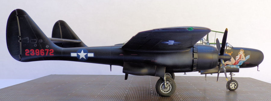
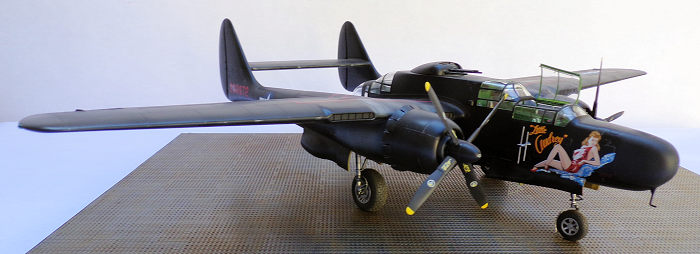
I applied a coat of Tamiya Grey surface primer to the model, checked for and corrected any flaws in the finish, and then sanded down the entire primer coat with a 3600 grit micromesh cloth. The subject of the model had an overall gloss black paint job. I had read that to get an all black finish with some scale effect, one should mix a little brown paint into the black paint. I decided to try it and came up with a mix of 8 x Tamiya X1 gloss black and 2 x Tamiya XF10 Flat Brown. This mix provided a black finish with a very slight brown tint. After a coat of the black/brown mix dried. I shaded selected panels of the airframe with thin coats of Tamiya XF85 Rubber Black. I was only able to find two photos of the model's subject. One photo showed a clean glossy finish with minimal chipped and faded paint. The other photo was a close up of the forward fuselage. That photo must have been taken at a later date as it
showed a much duller and worn finish. I decided to keep the weathering fairly restrained and used Silver Prismacolor pencil to simulate minor chipping on the leading edges of the flying surfaces, on the edges of various access panels, and on the engine cowlings..
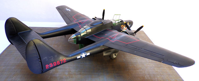
I wasn't inspired by either of the two decal options
that the kit provides and decided to go with a scheme that I found on Kits-World
KW148003 1/48 P-61 Black Widows. The Kits-World decals provide the nose art and
serial numbers for seven P-61s and the modeler has to use national insignia,
stencils, and walkway markings from either the kit decals or another aftermarket
source. I used the serial number and nose art from the Kits-World decals for
“Little Audrey” , a European
 Theater of
Operations (ETO) based P-61B-15-NO assigned to the 422nd
Night Fighter Squadron (NFS). The Kits-World decals added another level of
aggravation to an increasingly frustrating project. One of the serial number
decals wrinkled up after being wetted and refused to lay down. Since the sheet
provided six other serial numbers, I thought that I could combine letters and
numbers from the remaining serial numbers to duplicate a replacement for the one
that was destroyed. Unfortunately, the Kits-World serial numbers were all
slightly different sizes. The nose art decal was too big to fit on the fuselage.
I didn't discover this until I tried to apply the decal. I noticed on the
instructions that the decals were dedicated for the Monogram/Revell kit, but I
couldn't believe that their was that big of a discrepancy in the sizes of the
fuselages between the two kits. I took a closer look at my reference photos and
determined that the bottom portion of the nose art was actually painted on the
upper section of one of the nose landing gear doors. Unfortunately, my efforts
to apply the decal had already damaged it beyond repair and I had to order a new
sheet of decals. I fault Kits-World for not providing the decal in two parts or
at least notifying the modeler that it needed to cut to fit. The remainder of
the decals came from the kit. After the decals had settled and dried, I applied
a coat of Tamiya X35 Semi Gloss Clear. After the clear coat dried, I sprayed
light coats of heavily thinned (about 50 parts thinner to one part paint) Tamiya
XF19 Sky Grey acrylic on the sides, top, and bottom of the tail booms just aft
of the cowlings to simulate exhaust staining. I completed the model's finish by
spraying the fiberglass area of the radome with Tamiya XF86 Clear Flat.
Theater of
Operations (ETO) based P-61B-15-NO assigned to the 422nd
Night Fighter Squadron (NFS). The Kits-World decals added another level of
aggravation to an increasingly frustrating project. One of the serial number
decals wrinkled up after being wetted and refused to lay down. Since the sheet
provided six other serial numbers, I thought that I could combine letters and
numbers from the remaining serial numbers to duplicate a replacement for the one
that was destroyed. Unfortunately, the Kits-World serial numbers were all
slightly different sizes. The nose art decal was too big to fit on the fuselage.
I didn't discover this until I tried to apply the decal. I noticed on the
instructions that the decals were dedicated for the Monogram/Revell kit, but I
couldn't believe that their was that big of a discrepancy in the sizes of the
fuselages between the two kits. I took a closer look at my reference photos and
determined that the bottom portion of the nose art was actually painted on the
upper section of one of the nose landing gear doors. Unfortunately, my efforts
to apply the decal had already damaged it beyond repair and I had to order a new
sheet of decals. I fault Kits-World for not providing the decal in two parts or
at least notifying the modeler that it needed to cut to fit. The remainder of
the decals came from the kit. After the decals had settled and dried, I applied
a coat of Tamiya X35 Semi Gloss Clear. After the clear coat dried, I sprayed
light coats of heavily thinned (about 50 parts thinner to one part paint) Tamiya
XF19 Sky Grey acrylic on the sides, top, and bottom of the tail booms just aft
of the cowlings to simulate exhaust staining. I completed the model's finish by
spraying the fiberglass area of the radome with Tamiya XF86 Clear Flat.
| FINAL CONSTRUCTION |
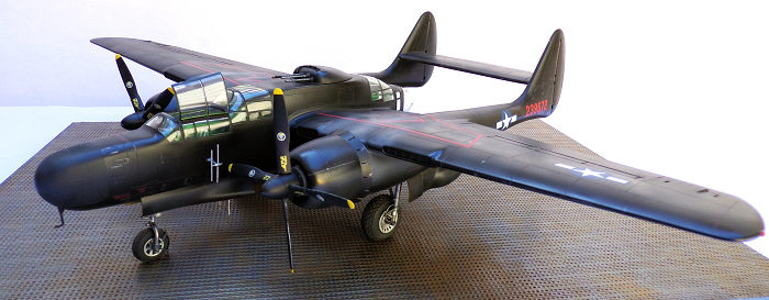
I assembled the main
landing gear legs and glued them into the gear's bays. After setting the
alignment and letting the glue dry, I attached the resin wheels and tires from
an Eduard aftermarket set, The kits wheels and tires are decent, but the Eduard
tires have separate wheels and better tread detail. I then attached the main
landing gear bay doors. Some sources state that the small forward door is the
only one open when the landing gear is in the down position, but about half of
the P-61 photos that I referenced showed all of the landing gear doors open when
the plane was on the ground so I attached all of the doors in the open position.
I glued the nose landing gear in the full down position, attached the nose
wheel, and attached the nose wheel's mudguard. The mudguard is attached to the
nose landing gear leg by a photo-etched brace. The brace has to be bent into
shape. GWH doesn't provide any guidance on bending the brace into the proper co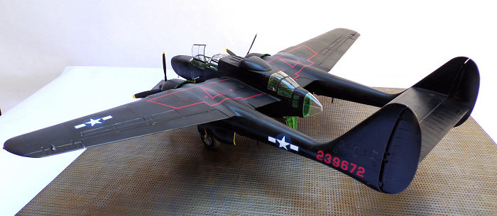 nfiguration
so the modeler has to rely on skill, luck, and a lot of trial and error to get
an acceptable result. With the model still inverted, I attached the nose landing
gear doors, and the crew access ladders. Both of the ladder's are integral with
access hatch's and the modeler has to fabricate the rungs of the radar
operator's ladder from small diameter sprue or wire.
nfiguration
so the modeler has to rely on skill, luck, and a lot of trial and error to get
an acceptable result. With the model still inverted, I attached the nose landing
gear doors, and the crew access ladders. Both of the ladder's are integral with
access hatch's and the modeler has to fabricate the rungs of the radar
operator's ladder from small diameter sprue or wire.
I flipped the model right side up and attached the engines, cowlings, and the propellers. The kit provides options for open or closed cowling flaps. I went with open flaps. The engines are loose fits in the cowlings and care should be taken to ensure the magnetos are properly oriented in the 2 and 10 positions before gluing the backs of the engines to the forward ends of the tail booms. I used a pair of Quickboost resin propellers instead of the kit parts. The Quickboost props have separate spinners and blades making painting them a little easier plus the blades are shaped better than the kit items. Quickboost also provides a handy tool for setting the pitch and alignment of the blades. I wanted to attach the escape hatch above the cockpit in the open position. GWH provides the hatch as a separate part, but does not provide any representation of the hinges or the prominent latching mechanism. I fabricated the hinges and the latch from styrene strip and steel wire. The hatch is attached to the canopy at tiny contact points and it wiggles alarmingly every time I move the model. I replaced the barrels of the 50 caliber machine guns in the dorsal turret with a set of Master turned brass items. I had to file down some of the turret mount's internal parts to get the guns to sit in the fully depressed position. The last parts to go on the model were the radar antennae on both sides of the fuselage just below the cockpit.
| CONCLUSIONS |
I was disappointed with the kit's indifferent fits and unfriendly engineering. I also have mixed feelings about the Kits-World decals. Why exactly same sized serial numbers on real aircraft would be different sizes on a scale models decal sheet baffles me. The model turned out to be more challenging than I expected, but I ended up with a decent miniature replica that pleased my wife and provided a nice tribute to my late father-in-law. For primarily those reasons it is the only model in my collection that has its own dedicated display case.
Rob
Hart 26 June 2026 Copyright ModelingMadness.com. All rights reserved. No
reproduction in part or in whole without express permission. If you would like your product reviewed fairly and fairly quickly, please
contact
the editor
or see other details in the
Note to
Contributors.