Monogram/Koster 1/48 PB4Y-1 Liberator
| KIT #: | 5604/#14 |
| PRICE: | $38.95/9.95 |
| DECALS: | Two options |
| REVIEWER: | Stephen Young, MD |
| NOTES: | Microscale set # 48-46 Insignia, Aeromaster set #AN48803 White Numbers and Letters, and Aeromaster set #48-743 Oriental Liberators, Pt. 1, Fancy Art |
| HISTORY |
The Consolidated Aircraft Corporation
B-24 Liberator series of four engine bombers was the workhorse strategic bomber
of the United States Army Air Force in World War II although over shadowed in
fame by the Boeing B-17 Flying Fortress. It was built in larger numbers and more
versions than any other WWII American aircraft although it faded rapidly from
the scene after the end of hostilities except in U.S. Navy service. Immensely
versatile, the aircraft filled many roles as strategic bomber, transport,
passenger transport, tanker, and photo-reconnaissance and anti-submarine
aircraft. It served in every theater of the war and also in many Allied nations
air forces as well. The campaigns in which Liberators were flown and fought are
legendary over Europe, the Mediterranean, and the Far East. Less well known were
the use of the B-24 by the United States Navy as anti-submarine patrol aircraft
in the Battle of the Atlantic and their use as patrol bombers in the Pacific
campaign. The U.S. Navy Liberators were all designated PB4Y-1s and the service
received 997 aircraft starting with the B-24D model with the greenhouse nose.
The majority of Navy Liberators were D and J models although some were L and M
models with the Emerson nose turret. After combat experience demonstrated the
inadequacy of
 the glass nosed Liberator defensive armament, the Navy specified
modification of most subsequent aircraft to include the Engineering and Research
Corporation 250SH-2 spherical ball turret that was a depot retrofit to original
aircraft. The 250SH-2 turret was originally designed by Boeing Aircraft who
furnished blueprints and manufacturing support. The turret was a hydraulically
operated, self contained unit with two .50 caliber machine guns and 800 rounds
of ammunition per gun. In the Pacific theater of operations, Navy PB4Y-1
squadrons were based through out the western and central Pacific flying search
and strike operations (armed reconnaissance) against Japan using the aircraft in
ways the Consolidated engineers never envisioned as Navy crews pushed these big,
lumbering bombers down to altitudes as low as 50 feet as a tactic to gain
surprise, avoid enemy radar, and bomb and strafe enemy ships at mast head
height.
the glass nosed Liberator defensive armament, the Navy specified
modification of most subsequent aircraft to include the Engineering and Research
Corporation 250SH-2 spherical ball turret that was a depot retrofit to original
aircraft. The 250SH-2 turret was originally designed by Boeing Aircraft who
furnished blueprints and manufacturing support. The turret was a hydraulically
operated, self contained unit with two .50 caliber machine guns and 800 rounds
of ammunition per gun. In the Pacific theater of operations, Navy PB4Y-1
squadrons were based through out the western and central Pacific flying search
and strike operations (armed reconnaissance) against Japan using the aircraft in
ways the Consolidated engineers never envisioned as Navy crews pushed these big,
lumbering bombers down to altitudes as low as 50 feet as a tactic to gain
surprise, avoid enemy radar, and bomb and strafe enemy ships at mast head
height.
After reading aircraft historian Chuck Hansen’s article in 1985 in the American Aviation Historical Society Journal I was fascinated with the ERCO turret and hoped to be able to build such a Liberator one day. Bill Koster’s vacuform conversion kit made it a possibility without scratch building and years later additional motivation was provided by reading Alan C. Carey’s books documenting the history of the U.S. Navy patrol bombing squadrons in the Pacific during WWII. Mr. Carey documented the story of these men who often flew single plane missions up to 1000 miles across the trackless Pacific; many crews were lost in combat or simply vanished. It was a dangerous war and hundreds of brave young men died flying and fighting in Navy Liberators against the Axis powers. This article is dedicated to those who served.
| THE KIT |
Monogram's venerable 1/48th scale B-24D remains widely available in different boxings on Ebay and commercially as the Revell/Monogram boxing currently in production. I am primarily a out of the box builder so this project was started as a some what ambitious project (for me) to convert the B-24D to a U.S. Navy PB4Y-2 Liberator patrol bomber with a ventral radome for a APS-15 bombing and navigation radar in the location of the commonly installed Sperry ball turret. This was my first experience using any vacuform kit parts and as my building techniques have improved I tend to add or change things that seem to enhance the building experience and end result for me. I obtained the Monogram kit on Ebay for this project several years ago but subsequently Revell re-issued the kit and reissued the B-24J as well. Either kit will work for this conversion. The current production B-24D kit consists of 156 parts including optional parts and parts for a M2 High Speed Tractor (M2 Cletrac) although the boxing I used did not include the tractor. Panel lines are raised and there is no rivet detail except on the bomb bay doors although the real airplane surface was covered in rivets. The kit is rated skill level 2 and the current kit instructions are quite thorough and clear unlike the old Monogram picture instructions included in the boxing I used.
 I purchased the Koster conversion
directly from Bill Koster in the early 1990’s along with his PB4Y-2 Privateer
vacuform, resin, and white metal kit and both have languished in my modeling
collection these many years. Finally after returning to building instead of
collecting, I decided to go ahead with the conversion kit. The Koster kit
consists of two vacuform styrene sheets and one clear vacuform acetate sheet.
The kit includes parts to modify the Monogram kit with a choice of two nose
conversions with engraved panel lines. Most of the parts allow one to fabricate
the various turrets used in the different B-24 models including the Emerson
A-15, Consolidated Aircraft A-6 tail, Motor Products Corporation A-6B tail,
Sperry Ball Turret including a floor and white metal turret yoke, Martin A-3
dorsal, Martin A-30 “High hat” dorsal, and the ERCO 250-SH spherical nose
turret. It also includes basic parts to build the open rear tail gun position
used on some Pacific Theater B-24s as well as new nose parts for the B-24H, J or
L and the PBY4-1 mounting the ERCO turret. Some additional parts are included
for windows and bomb aiming panels unique to the different B-24 models as are
the basic parts for a Leigh Light that equipped some anti-submarine Liberators.
The instruction sheet is very basic with diagrams showing the parts needed
including which original kit parts should be used. A brief description of the
features found on the different USAAF B-24s and the PB4Y-1 are included. There
is a LOT of room for scratch building since no detail parts are included and the
kit is really not for beginners. This kit may still be available directly from
Bill Koster at Koster Aero Enterprises but occasionally one will appear on Ebay
for a fairly high price. I actually started this project in 2012 and it
languished at various stages of completion for prolonged periods as I got side
tracked on other projects. Ultimately the Erco turret construction provided the
last delay until inspired by Don Fogal’s recent completed excellent Koster
PB4Y-2 Privateer conversion of the Monogram B-24J.
I purchased the Koster conversion
directly from Bill Koster in the early 1990’s along with his PB4Y-2 Privateer
vacuform, resin, and white metal kit and both have languished in my modeling
collection these many years. Finally after returning to building instead of
collecting, I decided to go ahead with the conversion kit. The Koster kit
consists of two vacuform styrene sheets and one clear vacuform acetate sheet.
The kit includes parts to modify the Monogram kit with a choice of two nose
conversions with engraved panel lines. Most of the parts allow one to fabricate
the various turrets used in the different B-24 models including the Emerson
A-15, Consolidated Aircraft A-6 tail, Motor Products Corporation A-6B tail,
Sperry Ball Turret including a floor and white metal turret yoke, Martin A-3
dorsal, Martin A-30 “High hat” dorsal, and the ERCO 250-SH spherical nose
turret. It also includes basic parts to build the open rear tail gun position
used on some Pacific Theater B-24s as well as new nose parts for the B-24H, J or
L and the PBY4-1 mounting the ERCO turret. Some additional parts are included
for windows and bomb aiming panels unique to the different B-24 models as are
the basic parts for a Leigh Light that equipped some anti-submarine Liberators.
The instruction sheet is very basic with diagrams showing the parts needed
including which original kit parts should be used. A brief description of the
features found on the different USAAF B-24s and the PB4Y-1 are included. There
is a LOT of room for scratch building since no detail parts are included and the
kit is really not for beginners. This kit may still be available directly from
Bill Koster at Koster Aero Enterprises but occasionally one will appear on Ebay
for a fairly high price. I actually started this project in 2012 and it
languished at various stages of completion for prolonged periods as I got side
tracked on other projects. Ultimately the Erco turret construction provided the
last delay until inspired by Don Fogal’s recent completed excellent Koster
PB4Y-2 Privateer conversion of the Monogram B-24J.
| CONSTRUCTION |
My original intent was
to build the model essentially out of the box with the addition of the Koster
PB4Y-1 nose incorporating the ERCO 250-SH spherical nose turret in place of the
green house nose of the B-24D. I got a little carried away on the turrets during
the construction but otherwise the model followed the original plan. This
conversion would involve removing a portion of the nose from each half of the D
following the panel lines as shown on the Koster instruction sheet. The Koster
PB4Y-1 nose parts were then removed from the vacuum formed sheet using the usual
technique of marking the part with a fine point Sharpie marker pen followed by
scribing around the part with a sharp #11 scalpel blade. Once the parts were
free from the sheet each was sanded on #200 wet/dry sandpaper taped to a sheet
of glass until the black marker line was even all around each part. Final
sanding was done with a sheet of #400 wet/dry sandpaper. The right and left nose
sections were then attached to the fuselage halves using acrylic (solvent)
cement. This is possible since there is a flange built into the nose parts to
provide overlap across the joint. The remainder of the fuselage assembly
basically followed the Monogram instructions so the cockpit areas and
radio/flight engineer compartment was assembled including the instrument panel,
control wheels, and pilot and co-pilot seat. I added masking tape seat belts to
the seats but no other details to the cockpit instruments. The instrument panel
was painted dark green and with black instrument faces with white dry brushing
applied. I also added sheet styrene behind the pilot and co-pilot seats cut to
represent armor plate. I added a table and seat behind the co-pilot and a jump
seat behind the pilot made of sheet styrene for interest’s sake since the area
would be somewhat visible through the cockpit windows. I modified the flight
deck flooring for the bombardier compartment by cutting the floor section off at
the partial bulkhead as it would need to be slightly longer with the Navy PB4Y-1
nose. Unfortunately this model would require a lot of weight to avoid tail
sitting a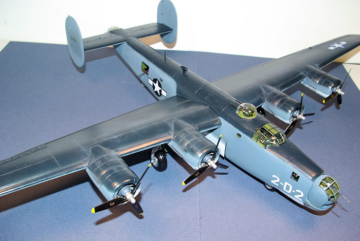 lthough Monogram provides a small boarding ladder to be used to prop up
the tail. I could not find a good solution to where to place the weights since I
also planned to leave the bomb bay doors open so no weight was inserted. The
fuselage gunner’s compartment assembly was assembled and a floor was made using
sheet styrene to mount the planned radome. The “D” kit does not provide a ball
turret but instead has a separate fuselage bottom piece to cover the opening in
this area. For that matter it also does not provide a “tunnel gun” option that
was a common installation in the early B-24D. The Koster conversion also
supplies piece for the turret opening as well as the ball turret floor but
neither component was needed since I used the kit supplied fuselage bottom
piece. I cut out a circular opening equal to the diameter of the radome that by
my measurements against available references appeared to be 0.75 inches in
diameter in 1/48th scale. The dome itself was vacuformed over a
wooden mold and painted radome tan based on one color photo I found of a PB4Y-1
with the radome in the lowered position. I suspended the dome partially through
the opening representing a fully retracted dome using a Plastruct styrene rod
attached to the roof of the fuselage. Once assembled the rear fuselage was
sprayed silver as many Liberators were left natural metal in this area, while
the floor itself was air brushed light brown to simulate the plywood floor. The
.50 caliber waist machine gun mounts need to be added at this stage also. I
added sheet styrene armor plate shaped to match reference photos and painted
interior green just behind each waist window. All interior compartment
components were attached to the right or left side of the fuselage. The bomb bay
parts were assembled to the fuselage sides per instructions. The kit bomb bay is
a very loose interpretation of the original configuration lacking the wing
center section but normally will not be visible with the model configured on the
ground. The next step was to glue both fuselage halves together using acrylic
cement applied a inch or so at a time along the seam. Unfortunately the fit is
somewhat poor at the rear bomb bay after bulkhead and a small gap remained at
the right fuselage side. It is only noticeable by looking up into the open bomb
bay. Once the fuselage join was dry quite a bit of Bondo auto body putty was
needed to fill the midline seam and the seams where the ventral fuselage piece
with the radome was attached to the bottom of the fuselage. Most B-24s sat on
the ground with the bomb bay doors partially opened to allow easy access for the
flight crew so I decided to build the model accordingly as the Monogram kit
provides door parts for either the open or closed options. I did not realize it
until after the doors were glued in place but the upper edge of each door should
be filed/sanded to a thin edge was designed to be flush with the fuselage sides
as the doors rolled up and open.
lthough Monogram provides a small boarding ladder to be used to prop up
the tail. I could not find a good solution to where to place the weights since I
also planned to leave the bomb bay doors open so no weight was inserted. The
fuselage gunner’s compartment assembly was assembled and a floor was made using
sheet styrene to mount the planned radome. The “D” kit does not provide a ball
turret but instead has a separate fuselage bottom piece to cover the opening in
this area. For that matter it also does not provide a “tunnel gun” option that
was a common installation in the early B-24D. The Koster conversion also
supplies piece for the turret opening as well as the ball turret floor but
neither component was needed since I used the kit supplied fuselage bottom
piece. I cut out a circular opening equal to the diameter of the radome that by
my measurements against available references appeared to be 0.75 inches in
diameter in 1/48th scale. The dome itself was vacuformed over a
wooden mold and painted radome tan based on one color photo I found of a PB4Y-1
with the radome in the lowered position. I suspended the dome partially through
the opening representing a fully retracted dome using a Plastruct styrene rod
attached to the roof of the fuselage. Once assembled the rear fuselage was
sprayed silver as many Liberators were left natural metal in this area, while
the floor itself was air brushed light brown to simulate the plywood floor. The
.50 caliber waist machine gun mounts need to be added at this stage also. I
added sheet styrene armor plate shaped to match reference photos and painted
interior green just behind each waist window. All interior compartment
components were attached to the right or left side of the fuselage. The bomb bay
parts were assembled to the fuselage sides per instructions. The kit bomb bay is
a very loose interpretation of the original configuration lacking the wing
center section but normally will not be visible with the model configured on the
ground. The next step was to glue both fuselage halves together using acrylic
cement applied a inch or so at a time along the seam. Unfortunately the fit is
somewhat poor at the rear bomb bay after bulkhead and a small gap remained at
the right fuselage side. It is only noticeable by looking up into the open bomb
bay. Once the fuselage join was dry quite a bit of Bondo auto body putty was
needed to fill the midline seam and the seams where the ventral fuselage piece
with the radome was attached to the bottom of the fuselage. Most B-24s sat on
the ground with the bomb bay doors partially opened to allow easy access for the
flight crew so I decided to build the model accordingly as the Monogram kit
provides door parts for either the open or closed options. I did not realize it
until after the doors were glued in place but the upper edge of each door should
be filed/sanded to a thin edge was designed to be flush with the fuselage sides
as the doors rolled up and open.
The wings were next. I was concerned about the strength of each wing since they are quite long in relationship to the width. I decided to reinforce the wing by adding a spar of 1/8 inch square K&S brass tubing epoxied to the top half of each wing. This spar extended into the slots that will line up the wings when assembled to the fuselage. The fit between the wing top and bottom at the nacelles is not too good and some filing and putty were needed to smooth out the joints there. The engine faces were painted by hand then assembled to the nacelles followed by adding the cowlings. More putty and filing/sanding is needed at the cowlings as well. The inside of the cowlings was painted with interior green. The two vertical stabilizers were attached to the horizontal stabilizer and all parts were then set aside for painting.
The most difficult part of the
construction was now the nose turret and the tail turret. The tail turret is
incorrect for a Navy PB4Y-1 and as far as I can tell from reviewing all
references available to me, all Navy Liberators as well as the PB4Y-2 Privateers
used the same Consolidated A-6 tail turret which is open where the guns extend
from the turret. Monogram provides a very simplified closed turret more
representative of the Motor Products Corporation A-6B turret as the tail turret
that was used on the tail of many B-24Hs and the nose of many B-24Js. In
addition the two clear parts are joined with a seam through the upper canopy of
the turret and will not be hidden; on the real turret this part of the turret
canopy was one piece of plexiglass. I decided to use the existing kit clear
parts and build up a turret interior from photos of the turret so I added right
and left panels cut from Evergreen sheet styrene (#4526 Metal Siding,
.040”spacing/.040” thick), a seat, sight and sight bar, control handles and some
wires to represent hydraulic plumbing. I did use the kit guns with some
modification and covered the open gun slots of the turret with a thin aluminum
sheet cut to fit with a hole drilled to allow the gun barrel to be inserted from
within the turret. The interior parts of the turret were airbrushed with Model
Master Interior Green and a dark was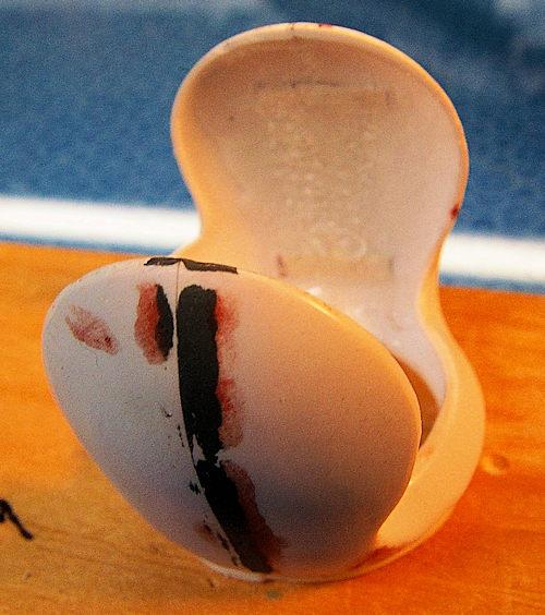 h mix of one part Future, one part water, Tamiya acrylic flat black XF-1, and Tamiya acrylic Red Brown XF-64 was used. I
assembled the turret halves after all the interior parts were added using CA in
the non-transparent areas and Testors Clear Parts Cement for the clear joint.
After assembly I think it is a definite improvement over the original parts in
appearance. Another option would be to build up the turret to represent the
Consolidated A-6 turret using the Koster parts but I wanted to save time for the
nose turret that would be more of a focal point for the model.
h mix of one part Future, one part water, Tamiya acrylic flat black XF-1, and Tamiya acrylic Red Brown XF-64 was used. I
assembled the turret halves after all the interior parts were added using CA in
the non-transparent areas and Testors Clear Parts Cement for the clear joint.
After assembly I think it is a definite improvement over the original parts in
appearance. Another option would be to build up the turret to represent the
Consolidated A-6 turret using the Koster parts but I wanted to save time for the
nose turret that would be more of a focal point for the model.
The spherical nose turret was more
challenging since the Koster kit only provides two halves of the sphere
vacuformed out of clear acetate and right and left parts of the turret trunnion/ring
as vacuformed styrene sheet parts. The Erco turrets were complex consisting of a
54 inch diameter sphere which contained the entire ammunition supply, the
hydraulic motor, control mechanism, operator and the machine guns
elevating/depressing on the trunnions. After cutting out the vacuform parts each
was carefully sanded to the correct cut line. Real care is needed here to test
fit the two ball halves and the trunnion halves. In addition the trunnion halves
have areas of very thin plastic due to the vacuum forming process. I decided to
join the trunnion halves after careful fitting with acrylic cement using small
tabs of scrap sheet styrene to reinforce the joint along both the right and left
sides of the trunnions. After this was cured I applied Zap-A-Gap cyanoacrylate
cement with dental resin to fill the trunnions in order to reinforce the joints
as well as along the turret ring part of the joints. This technique is well
described by master model builder Dr. Paul Budzik in one of his excellent
Y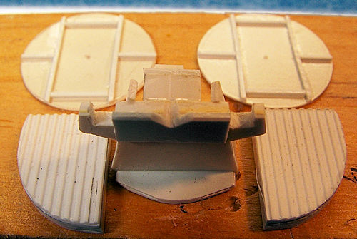 ouTube videos, and it works great to strengthen a fragile area. Unfortunately
dental resin is expensive and not generally sold outside the profession although you can perhaps obtain some through your personal dentist. Another option that
works reasonably well, but is much more coarse, is Arm & Hammer baking soda.
However, with the baking soda the CA sets up almost immediately so you must
allow for this in using it. Once this was cured all excess plastic was carefully
removed and the ball turret portion and the trunnion portion were constantly
test fitted to avoid removing too much material from the trunnions. This is
where the Koster quality is appreciated as the dimensions are quite close for
the vacuform parts. I decided to build up the turret interior rather than just
attach the kit guns into a empty ball since the interior is completely visible
through the large turret canopy. It is very important to note that the manner in
which the two ball halves are engineered, because when the turret is finished,
the bottom half is raised at the rear and the top half is depressed at the
front. This serves to hide th
ouTube videos, and it works great to strengthen a fragile area. Unfortunately
dental resin is expensive and not generally sold outside the profession although you can perhaps obtain some through your personal dentist. Another option that
works reasonably well, but is much more coarse, is Arm & Hammer baking soda.
However, with the baking soda the CA sets up almost immediately so you must
allow for this in using it. Once this was cured all excess plastic was carefully
removed and the ball turret portion and the trunnion portion were constantly
test fitted to avoid removing too much material from the trunnions. This is
where the Koster quality is appreciated as the dimensions are quite close for
the vacuform parts. I decided to build up the turret interior rather than just
attach the kit guns into a empty ball since the interior is completely visible
through the large turret canopy. It is very important to note that the manner in
which the two ball halves are engineered, because when the turret is finished,
the bottom half is raised at the rear and the top half is depressed at the
front. This serves to hide th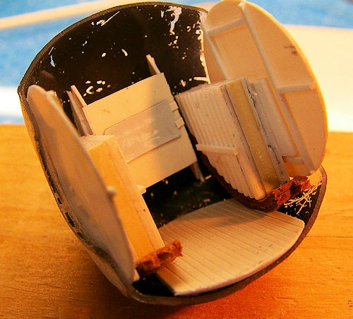 e seam in the non-transparent front of the turret
behind the front of the turret ring. The rear seam then consists of the turret
canopy and the back of the turret. After quite a bit of thought and planning, I
decided upon the construction process and it worked well. The first step is
trimming a half circular opening in each side of the turret sphere wall; the
walls need to be flat to allow fit in between the trunnions. I then cut a
circular wall piece of 0.010 sheet styrene that fit exactly inside each portion
of the parallel sides of the ball halves. This was glued with CA to the inside
of each acrylic turret half. This wall provided the foundation to build the rest
of the turret interior using Evergreen strip styrene and metal siding sheet
styrene to represent the ammunition boxes on each side of the turret. It is
important to note that when you build this up, the bottom half of the turret
must be angled to account for how the turret will sit within the trunnions in
its normal horizontal resting position. A circular turret floor with the sides
cut away to fit between the walls was added using 0.010 sheet styrene. I doubt a
flat floor actually exists in the actual turret and I could not verify this with
my available references but adding it really facilitates further construction.
The gun mount was built up of pieces of sheet styrene glued together and carved
to shape and the entire assembly was glued to the floor at the front of the
turret. Additional .010 sheet styrene was cut to represent the armor/back rest
and glued with CA to the back of the lower half of the turret. A seat was then
added as well as a control yoke built up of styrene pieces and styrene rod and a
sight bar using copper wire and a piece of clear sprue for the sight. A lot of
care must be taken to fit in the guns since
e seam in the non-transparent front of the turret
behind the front of the turret ring. The rear seam then consists of the turret
canopy and the back of the turret. After quite a bit of thought and planning, I
decided upon the construction process and it worked well. The first step is
trimming a half circular opening in each side of the turret sphere wall; the
walls need to be flat to allow fit in between the trunnions. I then cut a
circular wall piece of 0.010 sheet styrene that fit exactly inside each portion
of the parallel sides of the ball halves. This was glued with CA to the inside
of each acrylic turret half. This wall provided the foundation to build the rest
of the turret interior using Evergreen strip styrene and metal siding sheet
styrene to represent the ammunition boxes on each side of the turret. It is
important to note that when you build this up, the bottom half of the turret
must be angled to account for how the turret will sit within the trunnions in
its normal horizontal resting position. A circular turret floor with the sides
cut away to fit between the walls was added using 0.010 sheet styrene. I doubt a
flat floor actually exists in the actual turret and I could not verify this with
my available references but adding it really facilitates further construction.
The gun mount was built up of pieces of sheet styrene glued together and carved
to shape and the entire assembly was glued to the floor at the front of the
turret. Additional .010 sheet styrene was cut to represent the armor/back rest
and glued with CA to the back of the lower half of the turret. A seat was then
added as well as a control yoke built up of styrene pieces and styrene rod and a
sight bar using copper wire and a piece of clear sprue for the sight. A lot of
care must be taken to fit in the guns since
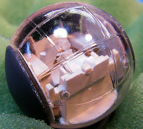 they will protrude through two holes
in the clear canopy portion of the turret. Lots of test fitting is needed here.
The turret interior was then airbrushed with interior green, small parts painted
as needed, and the dark wash applied. The canopy half of the turret was given a
treatment with Future floor polish and after drying painted before attachment.
The clear portions of the inside were masked off then the interior, which will
be visible, was airbrushed interior green. The exterior canopy was masked off
using small rectangles of Tamiya masking tape applied in a overlapping manner
within the frame lines and then airbrushed with MM interior green followed by MM
intermediate blue. After drying the masking was removed. I have used several
different methods to mask multi-pane canopies including Micromask and other
liquid masking agents; I think the Tamiya tape method with small cut rectangles
overlapped is the easiest for me as no cutting or tape trimming on the plastic
is needed. The guns were test fitted and glued in place with CA followed by
gluing the clear portion on using GS Hypo clear jewelry cement to attach the
flat portion to the interior walls and Testors Clear Parts Cement for the joint
at the canopy. It went together great until I realized I forgot to install the
armor glass window! It was too late to rectify without risking serious damage to
the turret so the next time it will be included when I build the Privateer. The
finished turret actually looks pretty good otherwise once assembled to the
trunnion with a light press fit.
they will protrude through two holes
in the clear canopy portion of the turret. Lots of test fitting is needed here.
The turret interior was then airbrushed with interior green, small parts painted
as needed, and the dark wash applied. The canopy half of the turret was given a
treatment with Future floor polish and after drying painted before attachment.
The clear portions of the inside were masked off then the interior, which will
be visible, was airbrushed interior green. The exterior canopy was masked off
using small rectangles of Tamiya masking tape applied in a overlapping manner
within the frame lines and then airbrushed with MM interior green followed by MM
intermediate blue. After drying the masking was removed. I have used several
different methods to mask multi-pane canopies including Micromask and other
liquid masking agents; I think the Tamiya tape method with small cut rectangles
overlapped is the easiest for me as no cutting or tape trimming on the plastic
is needed. The guns were test fitted and glued in place with CA followed by
gluing the clear portion on using GS Hypo clear jewelry cement to attach the
flat portion to the interior walls and Testors Clear Parts Cement for the joint
at the canopy. It went together great until I realized I forgot to install the
armor glass window! It was too late to rectify without risking serious damage to
the turret so the next time it will be included when I build the Privateer. The
finished turret actually looks pretty good otherwise once assembled to the
trunnion with a light press fit.
The Martin dorsal turret was just the kit components with some scrap plastic and fine wire additions to the turret ring to represent the portions of the turret that hang into the fuselage such as the ammunition boxes, seat, foot stirrup, etc. Most will not be well seen anyway but the added representations do improve the appearance when looking through the clear dome.
| COLORS & MARKINGS |
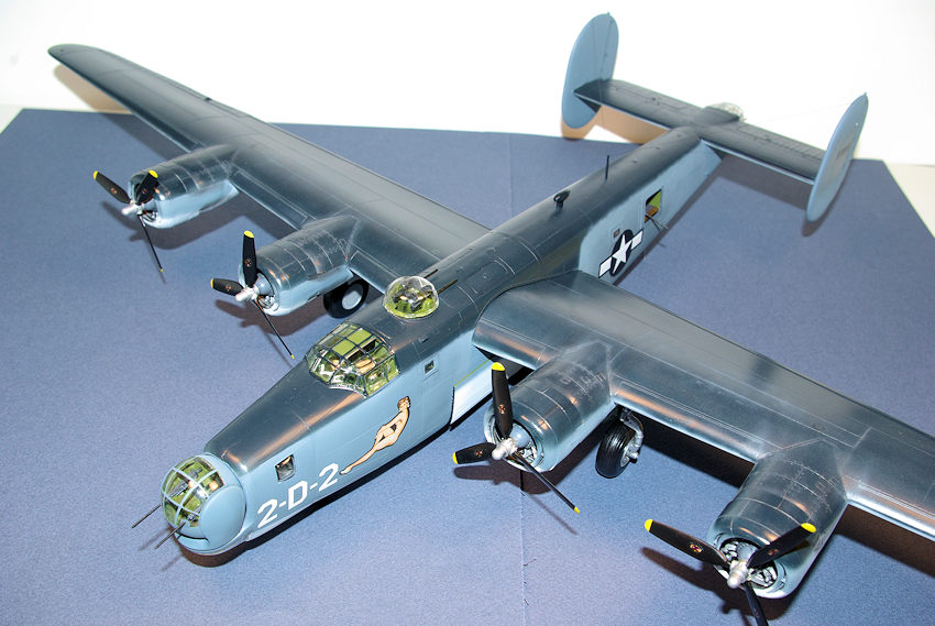
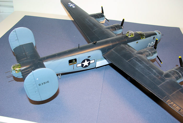
Looking through my print references as well as doing a online search for images I found one black and white photo in Robert Lawson’s book of a PB4Y-1P in flight in the tri-color scheme. That particular plane had the Erco nose turret and the nose window configuration matched the Koster nose so I decided to exercise artistic license and model it’s fictional sister ship to which I wanted to add nose art. Besides, I did not have any decals specifically representing an Erco nosed PB4Y-1 anyway.
The model was painted in assemblies doing
the fuselage, wings, and stabilizer separately since with everything attached
the model is large and un-wieldy to handle. SR-2C, Specification for Exterior
Colors, Insignia, and Marking of Naval Aircraft, January 5, 1943, specified what
is commonly known as the tri-color scheme. This consisted of semi-gloss and non-specular
(flat) sea blue upper surfaces, intermediate blue sides, and non-specular (flat)
white under surfaces. To model this and approximate what period photographs seem
to show I sprayed Rustoleum gloss white, Testors Model Master Intermediate Blue
(FS35164) and Testors Model Master Dark Sea Blue (FS15042) followed by a over
coating of Testors Gloss Cote to prepare for decals. Decals were sourced from
the Microscale national insignia WWII Blue Borders (#48-46) sheet, the
Aeromaster Oriental Liberators Part 1 Fancy Art (#48-712) sheet (for the nose
art), the Aeromaster ID numbers and letters (#AN48803) sheet, and the surplus
decal collection for the Bureau of Aeronautics number on the vertical tails.
After decals were applied, weathering was applied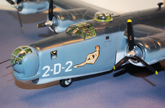 using pastel chalk as well as
Vallejo black airbrushed for the exhaust staining. Once completed the entire
model was given a coat of Testors Dull-Cote over the non-specular areas and
50/50 GlossCote/DullCote over the dark sea blue areas.
using pastel chalk as well as
Vallejo black airbrushed for the exhaust staining. Once completed the entire
model was given a coat of Testors Dull-Cote over the non-specular areas and
50/50 GlossCote/DullCote over the dark sea blue areas.
The model then proceeded
to final assembly of bomb bay doors, the wings to the fuselage, the horizontal
stabilizer, landing gear, antenna, canopy and turrets, propellers and other
parts. I filed triangular notches in the front and rear of each bomb bay door
part to represent the roller mechanism of the Liberator bomb bay doors, painted
the interior side Interior Green and the exterior Intermediate Blue and white
with the appropriate demarcation line. I glued each door to the fuselage side
(there are no locating pins/holes) matching to reference photos and using
Silicone sealant that does not dissolve the plastic or attack the paint. I used
the Monogram kit canopy that consists of three pieces although the fit is not
perfect and required some gap filling with Testors Clear Parts Cement. All clear
parts were dipped in Future floor wax and dried for at least two weeks (the
longer the better in my experience) prior to painting or attachment. To prevent
dust or particle contamination after dipping the clear part in Future, I place
the coated part in a covered plastic container sitting on a small sheet of nylon
screen (used for screen doors) raised above the container bottom by Popsicle
sticks. This allows excess Future to drain off and prevents dust contamination.
To add interest I built up the instrument panel attached to the overhead midline
portion of the canopy using lead solder, sheet styrene and small pieces of scrap
styrene sheet to represent components of the small overhead instrument panels.
All clear pieces were attached with Testors clear parts cement. I hand painted
the frame with Testors Acryl Dark Sea Blue. Final assembly included attaching
the horizontal stabilizer to the fuselage. This step requires completion of the
tail turret and its installation since it will be trapped in place when the
stabilizer is attached. The wing halves were next. On the fuselage box where the
wing is inserted there are three slots to align with the wing tabs; the left
wing has one tab and the right wing has two. When correctly aligned these tabs
solidly lock the position and correct dihedral of the wings. For some reason
there are small ridges in the right box and I needed to remove these by
chiseling them out to facilitate a tight fit. Make sure you check for this if
you build this kit and test fit adequately. I used Zap-a-Gap cyanoacrylate for
the join first attaching the right, allowing the glue to set, then attaching the
left. The next step was attaching the main landing gear assemblies and these fit
into cone shaped openings in the lower wing/inner engine nacelle
 area. The fit
was very loose so care is needed to hold alignment while the join sets; I used Devcon 5 minute epoxy for its speed and adequate working time. If I build this
kit again I may use a different approach to avoid the sloppy fit; perhaps
tapping the post for a screw and screwing the landing gear leg into the lower
wing half before wing assembly. I bulged the main tires by heating the plastic
against parchment paper held against a clothes iron. The fit of the landing gear
strut doors was poor so one needed to be attached after the main strut was glued
in place.
area. The fit
was very loose so care is needed to hold alignment while the join sets; I used Devcon 5 minute epoxy for its speed and adequate working time. If I build this
kit again I may use a different approach to avoid the sloppy fit; perhaps
tapping the post for a screw and screwing the landing gear leg into the lower
wing half before wing assembly. I bulged the main tires by heating the plastic
against parchment paper held against a clothes iron. The fit of the landing gear
strut doors was poor so one needed to be attached after the main strut was glued
in place.
Two 500 pound bombs were added to the front and rear bomb bay bomb racks although many Pacific Liberators had additional fuel tanks occupying the front bomb bay. The waist guns were then added. All the guns were painted flat black and then given a light wash of very thinned acrylic flat white to add the illusion of depth. Two antenna wires were added using my daughter’s straight hair colored with a black marker. The antenna wires run from the vertical stabilizers to the mast on the dorsal fuselage attached to holes drilled with a #80 bit. The last assembly attached was the Erco nose turret that was glued in place using a very small amount of clear silicone sealant in case it needs to be removed in the future.
| CONCLUSIONS |
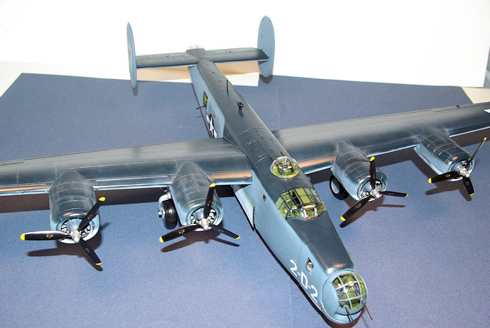
I’ve had a obsession with the Consolidated B-24 ever since I was a young boy fascinated by the service of my father in the United States Army Air Force and over the years collected books and articles of the airplane as well as kits. Despite having several B-24 kits from Monogram and Academy in my collection this was only my second completed B-24 model, the first being a ancient box scale Revell B-24J when I was a youngster. The venerable Monogram series of B-24D and B-24J kits remains the only versions in 1/48th scale although outdated in many aspects of fit, detail, and engineering compared to the leading kit manufacturer’s current offerings. It is a certainty that any new mold kit in this scale would be much more expensive although probably bringing much better detail and engineering. The real question is whether a new kit of a B-24 variant is ever manufactured in this scale. The Revell/Monogram kit has many over simplified features and some visible but significant inaccuracy issues but the part count is low and it builds up into an impressive model out-of-the-box due to size alone although it definitely benefits from as much modeling skill as one can muster. However with skill and effort as well as aftermarket parts it can provide the basis to build into a world-class model. The Koster conversion is relatively simple except for turret construction and detailing which adds another level of complexity. Once completed the model is quite large and display space is a challenge; it is way too large for any normal display cabinet which is where my other models reside. Completion of the project adds a rarely seen variant of the B-24 and a small tribute to the brave men who flew and fought in the Navy Liberators during World War II.
| REFERENCES |
We Flew Alone, United States Navy B-24 Squadrons in the Pacific, Alan C. Carey, Schiffer Military History, 2000
Above An Angry Sea, United States Navy B-24 Liberator and PB4Y-2 Privateer Operations in the Pacific, Alan C. Carey, Schiffer Military History, 2001
ERCO, Engineering and Research Corporation, Chuck Hansen, American Aviation Historical Society, Vol. 30, No. 1, Spring, 1985
B-24 Liberator in Detail, Bert Kinzey, Vol. 64, Squadron/Signal Publications, 2000
Bombers of World War II, Vol.1, Squadron/Signal Publications, 1981
B-24 Liberator in Action, No. 21, Steve Birdsall, Squadron/Signal Publications, 1975
B-24 Liberator in Action, No. 80, Larry Davis, Squadron/Signal Publications, 1987
B-24 Liberator in Action, David Doyle, Squadron/Signal Publications, 2012
Liberator! David Klaus, IPMS –USA 1989 National Convention publication, 1989
Valom h
First th
| FINAL CONSTRUCTION |
Thanks to for the peview kit. You can find this kit at your favorite hobby shop or on-line retailer.
If you would like your product reviewed fairly and fairly quickly, please contact the editor or see other details in the Note to Contributors.