|
KIT: |
Heller 1/72 P-40E Warhawk |
|
KIT # |
083 |
|
PRICE: |
$1.00 back in the dark ages of modeling |
|
DECALS: |
One aircraft |
|
REVIEW & |
Peter L’Heureux |
|
NOTES: |
CMK cockpit, True Details wheels, Squadron vac canopy and Aeromaster decals used |
|
HISTORY |
There was a feeling running through the military establishment almost up to the start of World War II that the United States would be practically invulnerable to attack by aerial bombardment. Hence, the philosophy of "ascendancy of bombardment over pursuit" dominated military planning in 1937 when the Curtiss P-40 first appeared.
The P-40 Warhawk, or Kittyhawk (export name) traces it’s lineage back to the Curtiss P-36 (Model 75) Hawk, some of which had been sold to the French prior to the war to bolster their Armee de l’air. The P-36 was powered by an air-cooled radial engine. The next step toward the P-40 was the P-37, a reworked P-36 incorporating an Allison V-1710 V-12 inline watercooled engine. This particular engine also had the benefit of a General Electric turbosupercharger to boost horsepower. The plane itself featured a cockpit pushed very far to the rear to balance the center of gravity. Thirteen YP-37s were built, but the project was abandoned due to turbosupercharger problems. Curtiss designer Donovan Berlin realized that the radial powering the P-36 was at its development limit, so he requested and got permission from the US Army Air Corps to install an 1150 hp Allison V-1710-19 engine with integral supercharging in one of his P-36s (Serial No. 38-10). The project was given the company designation of Model 75P, and the USAAC gave it the fighter designation of XP-40.
 There had to be
considerable reworking of the engine plumbing to get it to fit in the P-36
airframe. The carburetor intake for the single-stage supercharger was installed
in the upper nose cowling, between two fifty caliber Browning machine guns. The
oil cooler was mounted underneath the nose, with the radiator located in a
ventral position aft of the wing. The cockpit remained in the same position as
the P-36. The XP-40 took to the air for the first time on October 14, 1938, with
Edward Elliot as test pilot. Armament consisted of two 0.5-inch machine guns in
the nose, with four 0.3-inch guns in the wings. Performance was found to be
poor, the aircraft barely reaching 300 mph for top speed. The engine coolant
radiator was moved to the front of the aircraft, just under the nose. The
radiator intake was redesigned to include an oil cooler as well as two coolers
for the ethylene glycol engine coolant. The initial exhaust ports on each side
of the fuselage were removed, and six separate exhaust ports on either fuselage
side were installed. Top speed with these modifications was 342 mph at 12,200
feet, faster than the Hawker Hurricane, but still slower than the Bf-109 and
Supermarine Spitfire.
There had to be
considerable reworking of the engine plumbing to get it to fit in the P-36
airframe. The carburetor intake for the single-stage supercharger was installed
in the upper nose cowling, between two fifty caliber Browning machine guns. The
oil cooler was mounted underneath the nose, with the radiator located in a
ventral position aft of the wing. The cockpit remained in the same position as
the P-36. The XP-40 took to the air for the first time on October 14, 1938, with
Edward Elliot as test pilot. Armament consisted of two 0.5-inch machine guns in
the nose, with four 0.3-inch guns in the wings. Performance was found to be
poor, the aircraft barely reaching 300 mph for top speed. The engine coolant
radiator was moved to the front of the aircraft, just under the nose. The
radiator intake was redesigned to include an oil cooler as well as two coolers
for the ethylene glycol engine coolant. The initial exhaust ports on each side
of the fuselage were removed, and six separate exhaust ports on either fuselage
side were installed. Top speed with these modifications was 342 mph at 12,200
feet, faster than the Hawker Hurricane, but still slower than the Bf-109 and
Supermarine Spitfire.
At the start of WW II, the P-40 was already obsolete by European standards, but along with the P-39 Airacobra, it was all the USAAC had to stem the onslaught of the Japanese in China and Burma. It could not exceed the performance of the Zero fighter in anything but diving speed, and tactics were built around this advantage.
An order dated February 18, 1941 increased the P-40’s armament to six 0.50-inch Brownings in the wings, and the model designation was Model 87-B2. The USAAC called it the P-40E. The engine was upgraded to the Allison V-1710-39 V-12, producing 1150 hp. Max speed at 15,000 feet was 362 mph. Climb rate was 2100 fpm, with a service ceiling of 29,000 feet. Although outclassed by fighters of the Axis forces, and later by aircraft of the U.S., it speaks volumes for the plane that it accomplished what it did in the hands of skilled pilots.
The P-40 even came under criticism from Congress because of its lackluster performance. The Senate Special Committee to Investigate the National Defense Program, otherwise known as the "Truman Committee" after the chairman, then Senator Harry Truman, called the War Department to task because of the original volume purchase of an inadequate design and its continued production long after far more capable designs were readily available. It was finally concluded that this was not brought about by any undue favoritism to Curtiss Aircraft Co.
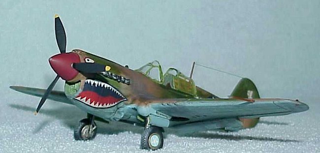
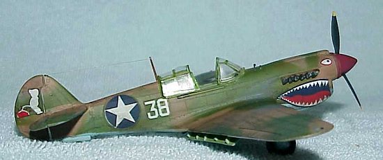
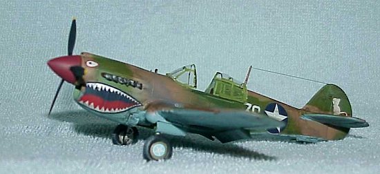
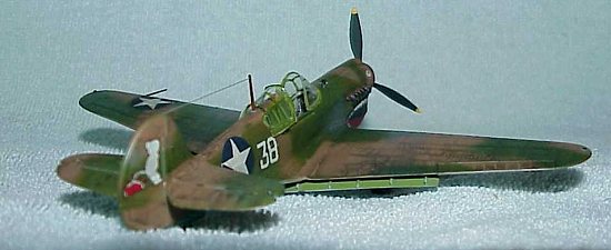
The P-40E depicted here is from the 51st fighter group, based in Paeshewa, China during October of 1943 (according to the Aeromaster illustrations provided with the decals). The aircraft is named "Holdin’ My Own", and a close look at the depiction of the little farmer boy on the tail might give you a clue why (hint: he’s doing something to the Rising Sun).
|
THE KIT |
 Heller presents it’s
P-40E on two sprues of injection molded gray plastic, along with one small clear
sprue containing the canopy parts. In judging the parts of these sprues, I can
divide them into two main categories – the airframe and everything else. The
airframe presents itself with relatively good, crisp detail on the outer
surfaces consisting of raised panel lines and rivets. There are two small sink
marks on both of the upper main wing halves near the machine guns, but these are
easily filled with putty, which I did. All the other small parts that are
supposed to be glued to the main airframe, with the exception of the gun aiming
ring, were clunky and generally out of scale.
Heller presents it’s
P-40E on two sprues of injection molded gray plastic, along with one small clear
sprue containing the canopy parts. In judging the parts of these sprues, I can
divide them into two main categories – the airframe and everything else. The
airframe presents itself with relatively good, crisp detail on the outer
surfaces consisting of raised panel lines and rivets. There are two small sink
marks on both of the upper main wing halves near the machine guns, but these are
easily filled with putty, which I did. All the other small parts that are
supposed to be glued to the main airframe, with the exception of the gun aiming
ring, were clunky and generally out of scale.
However, for the landing gear, cockpit, and canopy, my friend, T. Garth Connelly, provided me with the CMK cockpit detail set for the 1:72 Hasegawa P-40E, as well as True Details wheels and a Squadron vacformed canopy. The model needs these parts to turn out decently. I was not able to determine what year this kit came from, as the box and the instructions give no clues. The instructions themselves are written on both sides of a single sheet in English, French, and German. They consist of two exploded drawings, and four sections of written instructions. A parts list is included for ready reference to the sprue parts. Also included is a painting and camouflage guide, but the paint names are totally inaccurate. Best to check good references on this. A decal sheet depicting a P-40E from the Indian Air Force is included, but I was kindly provided with Aeromaster decals from our intrepid editor of Modeling Madness.
|
CONSTRUCTION |
Before I began construction, I washed all the parts in warm water and dishwashing detergent to remove the mold release agents, then rinsed them and left them on paper towels to dry. A lot of kits start off construction with the cockpit interior, but I didn’t want to, as I was going to cut and reposition the main flaps, elevators, and rudder. So out came the x-acto knife, scriber, and razor saw. I scribed along the guide lines of the lower main wing where the flaps were, putting vinyl tape on both sides of the lines to avoid marring the surrounding plastic (I learned that lesson the hard way). This was followed by cutting with both my x-acto knife and razor saw until I had freed the flaps, which come almost to the midpoint of the lower wing. I used the same procedure for the elevators. For the rudder, I cut out the two rudder halves from each fuselage half, then glued the rudder halves together with Testor’s cement, then put that assembly aside to dry. Using a combination of sanding sticks and pads, I cleaned up the cuts from the other pieces, and put them in a Zip-Lock bag to keep them from loss (another lesson learned the hard way).
Continuing with the lower main wing, I proceeded to drill out and file square the shell ejector outlets, then cut some thin rectangular pieces of Squadron sheet stock to depict the interspar longerons that were visible on the actual aircraft in the main landing gear bays. I attached these with CA glue, making sure they were squared up with the lower wing. A little trip to the primer shop was called for here, and I sprayed the interior of the lower wing in the landing gear bays, the exposed areas of the upper main wing halves that would show because I cut away the flaps, the interior side of the cutaway flap pieces, and the interior of both halves of the fuselage with Model Master enamel primer.
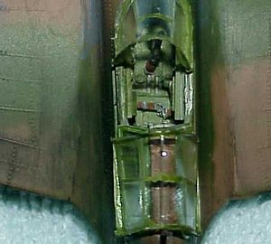 While these pieces were
drying, I turned my attention to the CMK cockpit set. It consists of
polypropylene plastic pieces including both walls of the cockpit, the seat and
floor, plus the gun sight and joystick. These were thin, and looked scale. Also
provided were brass photoetched parts for the rudder pedals, throttle and
mixture controls, and seat belt/harnesses, plus a vacformed canopy which I
didn’t use. I washed all parts well in soapy water to remove the molding agents,
and allowed them to air dry on paper towels. After drying, I carefully cut out
the polypropylene pieces with an x-acto knife, and followed the assembly
instructions, cutting the photoetched pieces as needed with a straight-edged
razor and adding them to the assembly. The instrument panel/rudder pedal
combination was a separate assembly. After allowing the assemblies to dry for a
day, I proceeded to prime them by hand, because I somehow couldn’t get the
primer from my airbrush to stick. After allowing the primer to dry for another
day, I airbrushed the CMK cockpit assembly with US Interior Green enamel, which
did adhere this time, along with the main wing parts that I had primed before
hand. I know you’re all saying "The gear bays should have been zinc chromate!",
and you’re right, but I felt lazy. I hand painted the instrument panel flat
black-gray, followed by painting the instruments white with silver drybrushing
to highlight them. I dryfitted the panel assembly into the fuselage, only to
find that the two halves didn’t quite want to fit around it properly, so I had
to carefully shave some of the panel on both sides in order to get the fuselage
to close. Once I was certain of this, I drybrushed zinc chromate on the fuselage
walls and cockpit assembly, followed by drybrushing with steel. The seat belts I
painted tan, with off-white shoulder harnesses and silver buckles.
While these pieces were
drying, I turned my attention to the CMK cockpit set. It consists of
polypropylene plastic pieces including both walls of the cockpit, the seat and
floor, plus the gun sight and joystick. These were thin, and looked scale. Also
provided were brass photoetched parts for the rudder pedals, throttle and
mixture controls, and seat belt/harnesses, plus a vacformed canopy which I
didn’t use. I washed all parts well in soapy water to remove the molding agents,
and allowed them to air dry on paper towels. After drying, I carefully cut out
the polypropylene pieces with an x-acto knife, and followed the assembly
instructions, cutting the photoetched pieces as needed with a straight-edged
razor and adding them to the assembly. The instrument panel/rudder pedal
combination was a separate assembly. After allowing the assemblies to dry for a
day, I proceeded to prime them by hand, because I somehow couldn’t get the
primer from my airbrush to stick. After allowing the primer to dry for another
day, I airbrushed the CMK cockpit assembly with US Interior Green enamel, which
did adhere this time, along with the main wing parts that I had primed before
hand. I know you’re all saying "The gear bays should have been zinc chromate!",
and you’re right, but I felt lazy. I hand painted the instrument panel flat
black-gray, followed by painting the instruments white with silver drybrushing
to highlight them. I dryfitted the panel assembly into the fuselage, only to
find that the two halves didn’t quite want to fit around it properly, so I had
to carefully shave some of the panel on both sides in order to get the fuselage
to close. Once I was certain of this, I drybrushed zinc chromate on the fuselage
walls and cockpit assembly, followed by drybrushing with steel. The seat belts I
painted tan, with off-white shoulder harnesses and silver buckles.
Once all the paint was dry, I positioned the CMK cockpit assembly into the fuselage from underneath for a dryfit, and found that no matter what I did, there was a gap showing behind the pilot’s headrest. So I cemented the assembly in with Testor’s cement, and cut a little half-oval of Squadron stock to close up the gap, which I had painted Interior Green beforehand. The finishing touch was a tiny oval piece of genuine tanned leather I had obtained from work to act as the pilot’s headrest.
From this point on, I followed the kit assembly directions, the only difficulty being the gluing in of the main wing assembly to the fuselage. For one, there were gaps present at the wing roots. Not really a big deal. But I found that the wing assembly, dryfitted into the fuselage, had absolutely no dihedral. From reading previous reviews of buildups of other models that had the same problem, the solution I used was to tape across the wing in such a way as to force it up enough to create about a 10 degree (guestimate) dihedral. This also acted in closing up the wing root gaps to a certain extent. I now glued the main wing in place, and allowed it to dry with the tape in place for a day.
The next time I returned to my workbench, I removed the tape, and sighed a sigh of relief that the dihedral stayed in place. I worked to fill in and sand the wing root gaps smooth. After this, I sanded down the machine gun molded detail, because I felt it stuck out too far from the wing leading edges, and looked clunky. Once I got it down to where I was satisfied, I drilled out the machine gun ports on both sides, then it was on to the paint shop.
|
PAINT & DECALS |
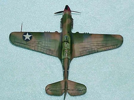
 After priming the whole
model with Model Master enamel primer in two coats, I traced the model onto
heavy copy paper, and using the Aeromaster illustrations as a guide, I freehand
traced the demarcation lines for the camouflage pattern, then proceeded to mark
the pieces to designate whether they masked the earth brown or medium green
areas. I then cut these pieces out, and put them aside. I airbrushed a custom
mix of Model Master paints to give a light sky blue on the undersurface, which I
allowed to dry for a couple of days, then completely masked off with Scotch 3M
masking tape. I then attached the masking paper pieces marked for green on the
model first with pieces of Scotch tape underneath to lift them up off the model
a little, as I wanted feathered edges to my camouflage. I airbrushed Model
Master earth brown first, then when that had dried for a day, I applied the
brown marked masking pieces and airbrushed Model Master medium green. It gave me
the feathered edge pattern I was looking for.
After priming the whole
model with Model Master enamel primer in two coats, I traced the model onto
heavy copy paper, and using the Aeromaster illustrations as a guide, I freehand
traced the demarcation lines for the camouflage pattern, then proceeded to mark
the pieces to designate whether they masked the earth brown or medium green
areas. I then cut these pieces out, and put them aside. I airbrushed a custom
mix of Model Master paints to give a light sky blue on the undersurface, which I
allowed to dry for a couple of days, then completely masked off with Scotch 3M
masking tape. I then attached the masking paper pieces marked for green on the
model first with pieces of Scotch tape underneath to lift them up off the model
a little, as I wanted feathered edges to my camouflage. I airbrushed Model
Master earth brown first, then when that had dried for a day, I applied the
brown marked masking pieces and airbrushed Model Master medium green. It gave me
the feathered edge pattern I was looking for.
Following two coats of Testor’s Gloss Coat, I applied the Aeromaster decals, which went down very well with setting solution onto the panel lines and rivets. I allowed them to dry for a day, then wiped the model down with a damp rag to remove the decal and setting residue. I then sealed the decals with another two coats of Gloss Coat.
I proceeded to use my wife’s Derwent watercolor pencils to create a watercolor wash of brown-black to the aircraft, going by what I had read several modelers did before. Using a wide soft brush, I applied a heavy wash of watercolor all over the aircraft, and allowed it to dry. The next day, I took dampened cotton swabs and brushed the plane in the direction of airflow, and was pleasantly surprised that the whole technique worked! The rivets and panel lines stood out. Hooray! Always a first time for everything. I sealed everything up with two coats of Dull Coat, and allowed to dry.
|
CONSTRUCTION CONTINUES |
 While waiting for the
paint to dry, I had been preparing the main landing gear to accept the True
Details wheels. I had to saw away the clunky-looking round plastic at the bottom
of each landing gear leg, file and sand it smooth and round (didn’t come out
quite the way I wanted, though). Taking my pin vise, I drilled small holes in
the bottom of each landing gear leg, and inserted pieces of steel wire, thick
enough to support the wheels and the weight of the model. I then drilled the
same size holes in the TD wheels, and glued them onto the pieces of wire. I used
wire from bread wrapper ties to depict the brake lines, which I painted flat
black. The TD tires themselves were painted my own blend of paints for tire
black, then the treads were rubbed with pencil graphite and drybrushed a medium
gray. The landing gear legs were painted steel, with the oleos in silver. These
assemblies were glued into the main landing gear bays, along with the gear
doors. After drying, the star decals were applied to the TD wheels. I fashioned
the radio mast and pitot tube out of stretched sprue, and used thin stretched
sprue for the aerial antenna. I cut and painted up the Squadron canopy and glued
it to the cockpit area with white glue, and the model was complete.
While waiting for the
paint to dry, I had been preparing the main landing gear to accept the True
Details wheels. I had to saw away the clunky-looking round plastic at the bottom
of each landing gear leg, file and sand it smooth and round (didn’t come out
quite the way I wanted, though). Taking my pin vise, I drilled small holes in
the bottom of each landing gear leg, and inserted pieces of steel wire, thick
enough to support the wheels and the weight of the model. I then drilled the
same size holes in the TD wheels, and glued them onto the pieces of wire. I used
wire from bread wrapper ties to depict the brake lines, which I painted flat
black. The TD tires themselves were painted my own blend of paints for tire
black, then the treads were rubbed with pencil graphite and drybrushed a medium
gray. The landing gear legs were painted steel, with the oleos in silver. These
assemblies were glued into the main landing gear bays, along with the gear
doors. After drying, the star decals were applied to the TD wheels. I fashioned
the radio mast and pitot tube out of stretched sprue, and used thin stretched
sprue for the aerial antenna. I cut and painted up the Squadron canopy and glued
it to the cockpit area with white glue, and the model was complete.
|
CONCLUSIONS |
Well, this model would probably not rank high as a recommended kit if you were looking for detail on an OOB build, but with aftermarket parts like I used here, plus some patience, you can build a fairly decent 1:72 P-40E cheaply. The fit wasn’t too bad, but is far surpassed by the Japanese wonderkits. There were some out of scale clunky parts, mostly the main wheels, which are better thrown away, as they have HUGE sink marks in them. My thanks go to Scott Van Aken for providing the Aeromaster decals, and to T. Garth Connelly for providing the kit and aftermarket parts.
|
REFERENCES |
2. Anguluci, E., and Bowers, P., The American Fighter. Orion Books,
1987.
If you would like your product reviewed fairly and quickly by a site that averages thousands of visits a day, please contact me or see other details in the Note to Contributors.