Airmodel & Pavla 1/72 Culver PQ-14
| KIT #: | ? |
| PRICE: | Around $20.00 |
| DECALS: | See review |
| REVIEWER: | Joel Hamm |
| NOTES: | Limited run kits. Both OOP |
| HISTORY |
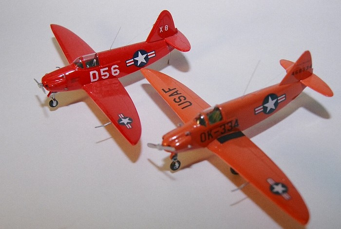
Comparing Two Culvers
It never rains, but it pours. As soon as one company
creates a kit of a long sought after subject, other moldmakers chime in
with me-too versions. One plane no one ever expected to see in model form
is the Culver PQ-14; but several years ago the German Airmodel firm came
out with a rough but adequate limited edition.. Rather than set their
sights on some new novelty, the Czech Pavla company chose to duplicate the
effort. Both build up into pert, colorful additions to any 1/72 scale
collection, if you can find them at a swap meet or collector’s site.
HISTORY: The Culver model’s appearance was unexpected because of the aircraft’s unglamorous role. Warplanes are designed to destroy the enemy, but the PQ-14’s purpose was to get itself blown to smithereens. It was the product of a 1940 Army Air Corps requirement for a radio controlled drone, to be used as a target for anti-aircraft gunnery training. It could be flown from the ground or a “mother” aircraft, but had a single-pilot cockpit for transport and maintenance flights. The first PQ-8 version was based on the civilian Cadet sport plane, which managed to coax 140 m.p.h. out of just 75 h.p.. The design came from the drafting pen of Al Mooney, whose company still produces private aircraft that squeeze the most performance out of the least power. Speed and maneuverability were the aim in designing target drones, which had to simulate the capabilities of modern aircraft. Improvements in the airframe, controls, and engine led to the PQ-14B. The twenty by thirty foot craft, weighing under 2000 lbs, was powered by a 150 h.p. six cylinder engine, pushing it to maximums of 185 m.p.h. and 17,000 ft. Over 2000 were procured by the USAAF, but half were transferred to the Navy, which re-designated it the TD2C-1. Despite its perilous existence, and wooden construction, quite a few still survive, on static display or in airworthy status, with the general name Cadet erroneously applied to the entire range of variants.
| THE KIT |
 THE PAVLA KIT: Side
by side kit comparison showed a nearly identical division of parts, and
similar molding quality. The Pavla, adorned with a few multi-media parts
and appearing to need less surgery, won the toss-up for first assembly. The
box art is certainly superior, offering clear clues to parts placement and
color. Instructions are also exceptionally helpful, showing the number and
color of each part, and precise milimetric measurements for scratch built
pieces, such as antennae and exhaust tubes. The sheet is even adorned with
semi-humorous cartoons. The large box disgorges a diminutive, but fairly
crisp sprue. On first examination, only the propeller needs replacement
from the spare parts box. The canopy is a clear, well molded vacu-form -
actually, two of them back to back, in case you booger one up (or decide to
replace the injected one on the Airmodel sister ship). An extensive decal
sheet offers three marking choices - two Air Force and one Navy. A fret of
etched brass parts is included, but most are incorrectly shaped (landing
gear links, canopy rails), oversize (nose gear door), or flat when they
should be round (pitot tube). With the exception of the seat belts, all are
more easily and accurately fashioned from plastic strips and scraps.
THE PAVLA KIT: Side
by side kit comparison showed a nearly identical division of parts, and
similar molding quality. The Pavla, adorned with a few multi-media parts
and appearing to need less surgery, won the toss-up for first assembly. The
box art is certainly superior, offering clear clues to parts placement and
color. Instructions are also exceptionally helpful, showing the number and
color of each part, and precise milimetric measurements for scratch built
pieces, such as antennae and exhaust tubes. The sheet is even adorned with
semi-humorous cartoons. The large box disgorges a diminutive, but fairly
crisp sprue. On first examination, only the propeller needs replacement
from the spare parts box. The canopy is a clear, well molded vacu-form -
actually, two of them back to back, in case you booger one up (or decide to
replace the injected one on the Airmodel sister ship). An extensive decal
sheet offers three marking choices - two Air Force and one Navy. A fret of
etched brass parts is included, but most are incorrectly shaped (landing
gear links, canopy rails), oversize (nose gear door), or flat when they
should be round (pitot tube). With the exception of the seat belts, all are
more easily and accurately fashioned from plastic strips and scraps.
| CONSTRUCTION |
Assembly is supposed to start with the cockpit interior - but don’t. There is plenty room for inserting seat and such after painting - which eliminates the need to mask. Building should begin by inserting an engine - a capitol omission on both kits. The actual airplane had prominent cylinders poking out of the cowl, but the kits have only a tear-drop dimple and empty inlets where these are supposed to be. Drill out the dimples; hollow out and thin down the cowl “cheek” plates. When these are glued to the fuselage halves, cut an appropriately sized cylinder from a spare radial engine and fasten it inside the cooling air inlet. Don’t bother adding weight to keep the tail off the ground. With that pug nose and short arm to the main landing gear, there is no way to stuff enough lead inside and still have room for cockpit details. One of two alternatives will have to suffice - a prop rod under the tail, or a bit of sticky stuff under the nose wheel. Drill holes in the nose section for the intake and exhaust pipes, insert the cockpit floor, then glue the fuselage halves together. They mate fairly well, with a bit of putty helpful in eliminating any misalignment.
After the wings have been “de-flashed”, they fit snugly into the fuselage. The fin and stabilizer have no locating pins, so study the drawings and box are for correct placement. The fin should be positioned so that the rudder hinge line is right at the stabilizer’s leading edge. Before attaching it, drill a small hole in the leading edge for mounting the wire antenna. Prior to painting, don’t miss adding a rudder trim tab and canopy rails, both of which are provided as brass pieces but are more easily made from plastic.
| COLORS & MARKINGS |
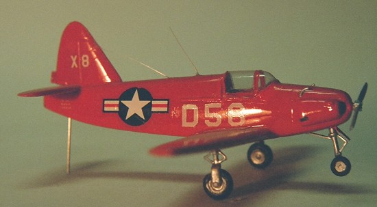
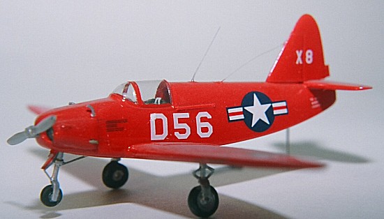
The Navy color scheme calls for gloss “insignia red”, but Testors Model Master makes this only in flat finish. Next door at their automotive paint rack, “guard red” or “Italian red” are indistinguishable from each other, or from the official Navy color. The Propagteam decals go on well - too well. Once they touch the plactic they refuse to slide, and must be positioned by holding a corner with a needle nosed forceps, inviting lacerations. Superscale insignia and letter replacements were used wherever needed. Paint and markings were sealed with a light coat of Future (Johnson’s Klear) floor wax, thinned 50% with acrylic thinner. The cockpit and wheel wells were brushed with zinc primer green, and the engine cylinders touched up with steel.
| FINAL CONSTRUCTION |
 The landing gear struts
are ragged, but better than anything scrounge-able from the parts bin.
After clean-up, torque links must be added. Only one per leg is provided
on the etched brass fret, but the main gear get two each. For one side,
links were cut from struts in the spares box, but for the other side they
had to be fashioned from super thin rod stock. Getting all four to look
symmetrical was no mean task. Strut mounting holes must be drilled in the
wells, but use a finger drill to avoid penetrating the upper wing
surfaces. The wheels are molded much the same as the struts - rough, but
of necessity useable. They were polished by gluing to 4d nail “mandrels”,
chucking in a rotary tool, and lathing smooth and round. The mains need to
be turned down a few microns in width and diameter to fit the struts, and
to have the proper appearance. MPM’s propeller emerged from the mold as an
unrecognizable slab. Rather than reshape it, I found a replacement from a
wreck, but this still required carving the constant speed hub to look like
a fixed pitch, a deception aided by the etched brass propeller hub. The
kit’s engine intake and exhaust pipes were also “flashy”, but too
diminutive to clean up. New ones were easily cut and bent from rod stock.
The landing gear struts
are ragged, but better than anything scrounge-able from the parts bin.
After clean-up, torque links must be added. Only one per leg is provided
on the etched brass fret, but the main gear get two each. For one side,
links were cut from struts in the spares box, but for the other side they
had to be fashioned from super thin rod stock. Getting all four to look
symmetrical was no mean task. Strut mounting holes must be drilled in the
wells, but use a finger drill to avoid penetrating the upper wing
surfaces. The wheels are molded much the same as the struts - rough, but
of necessity useable. They were polished by gluing to 4d nail “mandrels”,
chucking in a rotary tool, and lathing smooth and round. The mains need to
be turned down a few microns in width and diameter to fit the struts, and
to have the proper appearance. MPM’s propeller emerged from the mold as an
unrecognizable slab. Rather than reshape it, I found a replacement from a
wreck, but this still required carving the constant speed hub to look like
a fixed pitch, a deception aided by the etched brass propeller hub. The
kit’s engine intake and exhaust pipes were also “flashy”, but too
diminutive to clean up. New ones were easily cut and bent from rod stock.
Before filling the cockpit, a monofilament antenna wire was stretched from the previously poked hole in the vertical fin, through an aperture drilled in the turtleback, retrieved through the cockpit opening, stretched tight, and secured with super glue. A scratch-built instrument panel and glare shield, the brass pedals, a stretched sprue control stick, and bucket seat sporting brass belts all made for a cramped but convincing cockpit. A dorsal whip antenna came from pulled sprue, and a pitot tube from Evergreen rod stock. Cutting, trimming, and painting a vacu formed canopy is easier if first it is filled with water based wood putty to provide a rigid backing. Attaching it with Testors clear parts cement completed one half of this comparison. One drone down; one to be done.
| THE KIT |
 THE AIRMODEL
KIT: A closer exam of the Airmodel version revealed the
opportunity to practice more extensive modeling skills than indicated at
first glance. The parts breakdown is identical to the Pavla, but they are
neither literally nor figuratively from the same mold. The odd, translucent
white plastic is rough, both around the edges and on the surface, with
numerous pimples, dimples, and blemishes. Everything needs sanding and
touch-up or re-scribing of panel and control hinge lines. Several
critical challenges presented themselves. The cowl “cheek” panels are solid
chunks that need hollowing out to accept engine cylinders. The main wheel
well concavities are evident as convex shapes on the wing upper surface,
which needs more serious sanding, with probable loss of the raised wing
walk strips, which would benefit from replacement anyway. The nose wheel
well is molded closed and has to be cut open and a door formed. Neither is
there a cockpit floor to which the nose strut may be anchored. Speaking of
struts, all three are molded integral with their wheels, and while they
sprout the proper number of torque links, all are candidates for
stand-ins. The failure to find in the spares bin suitable surrogates for
the sister ship, emphasized the wisdom of keeping on hand an assortment of
generic resin or white metal “after market” wheels. To offset these
shortcomings, Airmodel provided a “flashy” but shapely propeller, and a
relatively well detailed instrument panel. The injected canopy is
acceptable, but would be exchanged for the extra vacu-formed transparency
so thoughtfully provided by Pavla.
THE AIRMODEL
KIT: A closer exam of the Airmodel version revealed the
opportunity to practice more extensive modeling skills than indicated at
first glance. The parts breakdown is identical to the Pavla, but they are
neither literally nor figuratively from the same mold. The odd, translucent
white plastic is rough, both around the edges and on the surface, with
numerous pimples, dimples, and blemishes. Everything needs sanding and
touch-up or re-scribing of panel and control hinge lines. Several
critical challenges presented themselves. The cowl “cheek” panels are solid
chunks that need hollowing out to accept engine cylinders. The main wheel
well concavities are evident as convex shapes on the wing upper surface,
which needs more serious sanding, with probable loss of the raised wing
walk strips, which would benefit from replacement anyway. The nose wheel
well is molded closed and has to be cut open and a door formed. Neither is
there a cockpit floor to which the nose strut may be anchored. Speaking of
struts, all three are molded integral with their wheels, and while they
sprout the proper number of torque links, all are candidates for
stand-ins. The failure to find in the spares bin suitable surrogates for
the sister ship, emphasized the wisdom of keeping on hand an assortment of
generic resin or white metal “after market” wheels. To offset these
shortcomings, Airmodel provided a “flashy” but shapely propeller, and a
relatively well detailed instrument panel. The injected canopy is
acceptable, but would be exchanged for the extra vacu-formed transparency
so thoughtfully provided by Pavla.
| CONSTRUCTION |
Construction proceeded according to the
same general sequence as Culver Number One, interrupted by required
additional steps. One of these, cutting a nose gear aperture, headed up the
procedure. First, the fuselage mating surfaces had to be “machined” flat
by rubbing on a sheet of 320 grit which has been taped to a glass plate.
The halves were taped together to mark the nose gear opening, then split
and cut with jeweler’s saw along the inked lines. While hollowing out the
cowl cheeks to make room for engine cylinders, t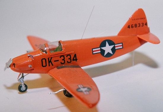 he
rotary burr slipped, taking out a chunk of cheek (airplane’s – not mine),
but providing the opportunity to crow about the greatest boon to modelers
since glue. Toss away those tubes of Bondo Body Putty, those
gap-filling acrylates that don’t, and non-shrinking fillers that do. Quit
concocting home-brewed nostrums of talcum powder and ear wax. For plugging
holes, bridging gaps, fairing joints, fixing boo-boos, reshaping parts, and
even casting new components, all that is needed is a twin-tube pack of
“Power Poxy” Advanced Plastic Mender. This resin + hardener paste
attaches to plastic without attacking it, sets up in minutes, then files
and sands with the same hardness and texture as poly-styrene. It even
handled the tricky task of re-contouring the engine air intakes, which
didn’t have the proper curve. A few caveats: The methacrylate formula
pours out pungent odors that aren’t appreciated by other householders; and
the exothermic cure reaches ctriticality at about a quarter of an ounce.
In less pedantic terms - a thumb-nail sized glop gets hot enough to soften
plastic; so keep the parts cool with a wet tissue, and the rest of the
family cool with an exhaust fan. Shaping a strip of sheet stock into a
cockpit floor / wheel well roof took considerable trial and error fitting,
after which the fuselage could be closed. The assembly had to be sanded
smooth, and the ground away canopy rails replaced by styrene strips.
he
rotary burr slipped, taking out a chunk of cheek (airplane’s – not mine),
but providing the opportunity to crow about the greatest boon to modelers
since glue. Toss away those tubes of Bondo Body Putty, those
gap-filling acrylates that don’t, and non-shrinking fillers that do. Quit
concocting home-brewed nostrums of talcum powder and ear wax. For plugging
holes, bridging gaps, fairing joints, fixing boo-boos, reshaping parts, and
even casting new components, all that is needed is a twin-tube pack of
“Power Poxy” Advanced Plastic Mender. This resin + hardener paste
attaches to plastic without attacking it, sets up in minutes, then files
and sands with the same hardness and texture as poly-styrene. It even
handled the tricky task of re-contouring the engine air intakes, which
didn’t have the proper curve. A few caveats: The methacrylate formula
pours out pungent odors that aren’t appreciated by other householders; and
the exothermic cure reaches ctriticality at about a quarter of an ounce.
In less pedantic terms - a thumb-nail sized glop gets hot enough to soften
plastic; so keep the parts cool with a wet tissue, and the rest of the
family cool with an exhaust fan. Shaping a strip of sheet stock into a
cockpit floor / wheel well roof took considerable trial and error fitting,
after which the fuselage could be closed. The assembly had to be sanded
smooth, and the ground away canopy rails replaced by styrene strips.
Minor but time-consuming plastic surgery stretched the assembly well beyond what such a diminutive airframe should have occupied. The tail cone had to be lengthened and notched to properly attach the delicately molded stabilizer. The rudder also needed extension with a piece of card stock to reduce the gap where it overhangs the stabilizer. The alternative act of shortening the vertical fin would have left it too stubby. The wing-to-fuselage joint demanded extensive excavation. Fortunately, both parts had plenty spare plastic to file away and flail away at. A final edge and surface sanding, followed by a rubdown with mild abrasive cleanser, revealed an airframe equal to Pavla’s.
| COLORS & MARKINGS |
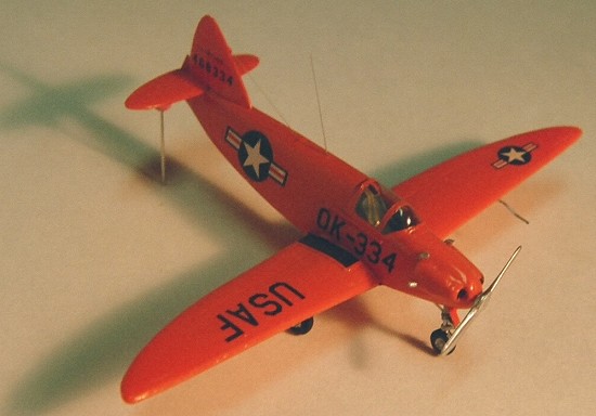
For the sake of variety, this one was painted in the gloss yellow-orange Navy livery. That shade is available in the Humbrol “Super Enamel” series, which in name and price only has been upgraded from plain old enamel. If they really wanted to make it “super” they would dispense it in jars, rather than those unusable, unpourable tinlets that waste half the contents around the lid rim.
| FINAL CONSTRUCTION |
All the previously mentioned bits’n’pieces had to be extensively cleaned up. Antennae, pipes, pito and such were fashioned from sprue or soldering wire. The canopy, though injected, was rejected in favor of the spare vacanopy (vacu-formed canopy, if you couldn’t figure it out) supplied with the Pavla kit.
| CONCLUSIONS |
Lots’a work for a coupl’a little kits; but that’s par for the course with limited edition stuff.
July 2006
Copyright ModelingMadness.com. All rights reserved. No reproduction in part or in whole without express permission from the editor.
If you would like your product reviewed fairly and fairly quickly, please contact the editor or see other details in the Note to Contributors.