Revell/Italeri 1/72 Do-24K
| KIT #: | 04362 |
| PRICE: | 15 Euros or so |
| DECALS: | Three options |
| REVIEWER: | Peter Neinhuis |
| NOTES: | Converted to Do-24K. Reboxed Italeri kit |
| HISTORY |
Maiden
flight of the V.3 was on 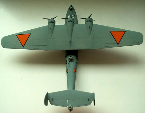 completed,
only 5 Dorniers were left. They were turned over to the Australian Forces and
they were due to service problems soon be replaced by better serviceable
material.
completed,
only 5 Dorniers were left. They were turned over to the Australian Forces and
they were due to service problems soon be replaced by better serviceable
material.
The
production of the Dutch Dorniers was done by several Dornier factories in
Germany and Switzerland, but they were also license built in the Netherlands by
Aviolanda and De Schelde, both experienced with full metal plane building and
both having close contacts with the Dutch Naval Services. During production, the
Do-24 was updated, armament was improved, fuel capacity was enlarged, engines
were replaced by more powerful ones. The X-1 to X-12 were armed with 3 7.9
Browning machine guns in 3 similar turrets, but from the X-13 the mid-upper
turret had a 20 mm Hispano Suiza 404 fast firing gun in a new designed turret.
Nice surprise for the Japanese Forces. Under the outer wings were 6 bomb racks
for a bomb load of 4x300 kg bombs, or 6 x 200 kg bombs or 12 x 50 kg bombs.
These bomb racks could be removed.
In the
mean time the Germans were making plans for producing their own Do-24’s, as
Do-24-T1 and later Do-24T2, of course with taking advantage of the Dutch
improvements. After the Germans overrun the
Because of it’s good design, good flying and floating capabilities it remained in SAR service until the late seventies, and the Dornier design teams kept on working on design improvements until the late nineties. A bit like the Douglas DC-3/C-47, the Dornier Do-24 is bit of a never ending story on the water.
| THE KIT |
 Well, there
are 2 options. The first, and probably the most sensible, just build the kit
straight from the box, and disregard all the misfits, missing details and wrong
parts for even a German or Dutch version. The kit has of course some aging
problems like sinkholes, scarce details, some flash, but the fit of the kit
parts is mostly OK. Take care when you assembly the wing on it’s mounts,
the alignment is a bit tricky. Not a shake and bake kit, but one that needs some
attention. Since the kit is a T version, who will tell the difference? Everybody
who has the right drawings or good detail pictures…….
Well, there
are 2 options. The first, and probably the most sensible, just build the kit
straight from the box, and disregard all the misfits, missing details and wrong
parts for even a German or Dutch version. The kit has of course some aging
problems like sinkholes, scarce details, some flash, but the fit of the kit
parts is mostly OK. Take care when you assembly the wing on it’s mounts,
the alignment is a bit tricky. Not a shake and bake kit, but one that needs some
attention. Since the kit is a T version, who will tell the difference? Everybody
who has the right drawings or good detail pictures…….
Second
option, take on the dirty job, and rebuild some parts of the kit. For each step,
it’s up to you to decide if you take the challenge… For a proper Dutch version
the following steps are necessary. Some of them, like the position of all the
porthole shaped windows, will look good on the German versions as well.
| CONSTRUCTION |
First,
the interior. You can buy a Goffy interior set, or you can adjust the interior
with some simple things. The seats are wrong, the Dutch seats didn’t have the
headrests, so they can be cut off, you can make a lowered floor between the
seats, you can make a floor in the radio-compartment, put some radio racks in
there too. A bulkhead in front of the cockpit (behind the instrument panel) and
a bulkhead at the end of the radio-compartment will make the most visible parts
of the interior complete.
 Up to the
serious misfits of this kit, the fuselage. All the porthole glass work are on
the wrong places. All these will have to be raised 2 mm in upwards direction.
The position of the nose turret is also 2 mm to far away from the windshield,
and the turret should be 2 mm lowered. That last thing can be done by making
some new supports under the lowest supports that are molded in the fuselage
halves. The top of the turret can also be removed. For a proper Dutch version,
check the number of the plane you want to built. The first batch, X-1 – X-12 had
3 similar turrets on the front, back and rear. All of the type that the kit
provides for the front turret only….. The last batch, X-13 - X-37 had a similar
nose and rear turret, and the mid-upper turret as the kit provides, with the 20
mm Hispano Suiza gun. A real piece of armament, as some Japanese
found out….
Up to the
serious misfits of this kit, the fuselage. All the porthole glass work are on
the wrong places. All these will have to be raised 2 mm in upwards direction.
The position of the nose turret is also 2 mm to far away from the windshield,
and the turret should be 2 mm lowered. That last thing can be done by making
some new supports under the lowest supports that are molded in the fuselage
halves. The top of the turret can also be removed. For a proper Dutch version,
check the number of the plane you want to built. The first batch, X-1 – X-12 had
3 similar turrets on the front, back and rear. All of the type that the kit
provides for the front turret only….. The last batch, X-13 - X-37 had a similar
nose and rear turret, and the mid-upper turret as the kit provides, with the 20
mm Hispano Suiza gun. A real piece of armament, as some Japanese
found out….
To solve
the problem of the turrets, you might contact the Revell Department X for
replacements, or make your own vac-formed turrets. I was lucky, and recycled my
old glass pieces of the first Do-24 I build 30 years ago.
 If you have
the corrected rear turret, you will need to widen the fuselage on the rear as
well, otherwise your new turret won’t fit. A 1,5 mm strip of sheet will do this
trick, together with trimming the hole for the turret.
If you have
the corrected rear turret, you will need to widen the fuselage on the rear as
well, otherwise your new turret won’t fit. A 1,5 mm strip of sheet will do this
trick, together with trimming the hole for the turret.
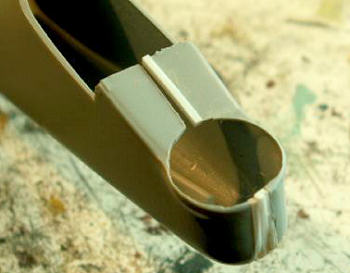
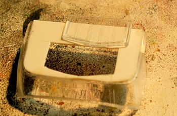 Last piece
of glass that needs some adjustments, is the canopy. The hatches on top of it
are wrong. You will only need the forward two. So I cut them out, and made a
replacement for the canopy roof from some sheet. The middle windows have a
strange stripe molded, so cut these out, and replace them with some clear
styrene as well.
Last piece
of glass that needs some adjustments, is the canopy. The hatches on top of it
are wrong. You will only need the forward two. So I cut them out, and made a
replacement for the canopy roof from some sheet. The middle windows have a
strange stripe molded, so cut these out, and replace them with some clear
styrene as well.
 Next
adjustment, is the making of the entrance hatch on the port side of the fuselage
on the Dutch versions. You will need to make a hole in the right position, and
make a hatch from some thin sheet material, and glue that over the hole. After
all the paintjobs, just simple fill the hole with Crystal Clear or
so.
Next
adjustment, is the making of the entrance hatch on the port side of the fuselage
on the Dutch versions. You will need to make a hole in the right position, and
make a hatch from some thin sheet material, and glue that over the hole. After
all the paintjobs, just simple fill the hole with Crystal Clear or
so.
 The next
simple job is getting rid of the ambulance doors for the Dutch version, simply
by filling the recessed panel lines that outline them. Another easy job, making
the strengthening strips you can see on the pictures of the real thing. They
start between the front turret and windshield, and go further behind the canopy
until the mid upper turret. You can make them from 1 mm thick sheet, with a
height of 0,8 mm. For a proper Dutch version, the next step is to remove the
bulge between the mid-upper turret and the tail. Fill the gap with some filler,
sand it down and this step is completed.
The next
simple job is getting rid of the ambulance doors for the Dutch version, simply
by filling the recessed panel lines that outline them. Another easy job, making
the strengthening strips you can see on the pictures of the real thing. They
start between the front turret and windshield, and go further behind the canopy
until the mid upper turret. You can make them from 1 mm thick sheet, with a
height of 0,8 mm. For a proper Dutch version, the next step is to remove the
bulge between the mid-upper turret and the tail. Fill the gap with some filler,
sand it down and this step is completed.
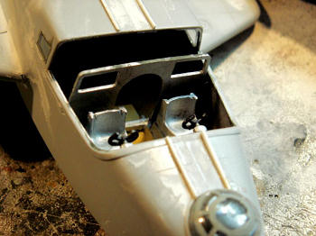
Last big
improvement on the fuselage can be made on the so called “stummels”, those big
stabilizing floats on both sides of the fuselage. They were used as floats, and
as fuel compartments. The detail that is missing here, are the 8 filler caps for
the Dutch planes on each side. The Kit only has one of them on each side, and
that i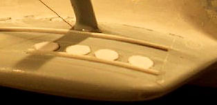 s a
bit scarce. You can make them by glueing some round pieces of thin trimmed
plastic sheet with the right diameter, on the right places.
s a
bit scarce. You can make them by glueing some round pieces of thin trimmed
plastic sheet with the right diameter, on the right places.
When you
have made these filler caps on the top parts of these stummels, there is some
thing else to take care of. The backend of the stummels isn’t as sharp as the
kit parts suggest. In fact the back ends were a bit straight. To achieve this,
the rear ends will be needing a strip of 1 mm thick plastic sheet. When you glue
the under and upper parts together, the small gaps on the sides can be filled
with some filler, and sanded down in the right shape.
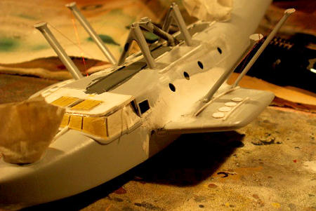
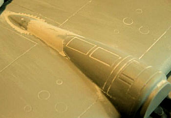
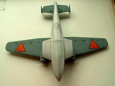
After
that comes the next difficult challenge, getting the shape right were the
stummels go into the fuselage. The shape is bit like the way the F-16 wings
smoothly transfer into the fuselage. Some layers of filler are needed, and after
that, the sanding in the right shape can take part
(see image at top of this section).
Making a shape of some cardboard for test fitting of
the shape can help you out on this. Last, but not least, the stummels will be
needing a pair of re-inforcing strips as the fuselage has. Two on each stummel.
Next
adjustment to be made on the fuselage, is removing the small hump at the end of
the fuselage. That can be cut off, and the small gap you get, can be simply
filled with some filler. Sand it down, and the shape is corrected for the Dutch
K versions.
 Next step,
the wing. The hump behind the central engine is to high, and was for the Dutch
versions more a lengthened piece of cowling. I drilled a lot of holes around the
hump, sanded the inside down, and placed it back in position. After that, some
layers of filler were needed to stretch the engine cowling. Sand it down in the
right shape, and you can move forward on the central wing piece.
Next step,
the wing. The hump behind the central engine is to high, and was for the Dutch
versions more a lengthened piece of cowling. I drilled a lot of holes around the
hump, sanded the inside down, and placed it back in position. After that, some
layers of filler were needed to stretch the engine cowling. Sand it down in the
right shape, and you can move forward on the central wing piece.
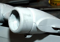
There
you will find three inlets, and they all have the wrong shape. They should be
round, and with a small strip of sheet can be turned into some real inlets.
Carefully sand the right shapes, because there is not very much material to sand
down. The inside of the parts will shine through the plastic when you’re ready.
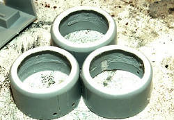 What’s
really wrong in this kit, the engines….. The Dutch Dorniers were fitted with
Wright Cyclone engines, and the kit has BMW’s… Only right thing about those is
the number of cylinders…. To get a real proper Dutch Dornier, you will have to
adjust here. Easy way, but not very good looking, take 3 left over engines from
that good old Airfix B-17, sand down the raised cooling flaps, put the kit props
on them, and glue all this on the engine mounts. A bit more work is adjusting
the kit parts. Cut off the front small ring, cut off the oil cooler intakes and
also cut off the cooling flaps. Glue a 1 mm thick piece of plastic sheet on the
front of the engine cowling, and reshape the cowling front in a more rounded
shape. When done, make an opening with a diameter of 10 mm in the centre, and
the engine cowling is almost ready. Just fill the gaps where the oil coolers
just to be, and sanding down the back end of the cowlings a bit, until the
length is good. Well, almost done. Some new
What’s
really wrong in this kit, the engines….. The Dutch Dorniers were fitted with
Wright Cyclone engines, and the kit has BMW’s… Only right thing about those is
the number of cylinders…. To get a real proper Dutch Dornier, you will have to
adjust here. Easy way, but not very good looking, take 3 left over engines from
that good old Airfix B-17, sand down the raised cooling flaps, put the kit props
on them, and glue all this on the engine mounts. A bit more work is adjusting
the kit parts. Cut off the front small ring, cut off the oil cooler intakes and
also cut off the cooling flaps. Glue a 1 mm thick piece of plastic sheet on the
front of the engine cowling, and reshape the cowling front in a more rounded
shape. When done, make an opening with a diameter of 10 mm in the centre, and
the engine cowling is almost ready. Just fill the gaps where the oil coolers
just to be, and sanding down the back end of the cowlings a bit, until the
length is good. Well, almost done. Some new
 oilcoolers
can be made of parts cut down before. Shape them in the right way, and place
them between the exhausts on top of the cowlings. The inside of the cowlings can
be filled with the kit engines, or with some Cyclones you might have in the
spare parts department. The kit props are OK, but the spinners are not of the
right shape and size. The Dutch spinners were shorter, and didn’t cover the
spaces between the prop blades. They also were a bit
rounder as the ones in the kit. However, the kit spinner can be easily reshaped
for this purpose. Cut the pieces of between the prop
blades, and sand the point down in a more rounded shape. Glue the spinners in
place, and most of the adjusting is now finally done.
oilcoolers
can be made of parts cut down before. Shape them in the right way, and place
them between the exhausts on top of the cowlings. The inside of the cowlings can
be filled with the kit engines, or with some Cyclones you might have in the
spare parts department. The kit props are OK, but the spinners are not of the
right shape and size. The Dutch spinners were shorter, and didn’t cover the
spaces between the prop blades. They also were a bit
rounder as the ones in the kit. However, the kit spinner can be easily reshaped
for this purpose. Cut the pieces of between the prop
blades, and sand the point down in a more rounded shape. Glue the spinners in
place, and most of the adjusting is now finally done.
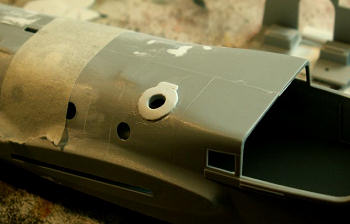
Job
almost finished, a minor adjustment, the landing
light. That should be rectangular for the Dutch versions, and that can be easily
made by making the round hole rectangular, just follow the panel
lines here. After that, make a lamp base, make a light inside, and find
some thin acetate that can be used as a clear cover of the light.
Last adjustments will be made on the rudders. Again, the shape is a bit the straight on the back ends, they have to be sanded down a bit in a more rounded shape.
| COLORS & MARKINGS |
There
are several scheme’s to choose from. The first batch, roundels, and
red-white-blue outside rudders. Plane call sign in big on the fuselage, near the
mid turret.
 Under
surfaces of the fuselage aluminium dope, rest of the plane in “Holland grijs”,
or Dutch grey. The tricky thing, what is the corresponding Humbrol number? I
went for Humbrol 87 for my kit. That can be a bit on the light side, but it
works for me.
Under
surfaces of the fuselage aluminium dope, rest of the plane in “Holland grijs”,
or Dutch grey. The tricky thing, what is the corresponding Humbrol number? I
went for Humbrol 87 for my kit. That can be a bit on the light side, but it
works for me.
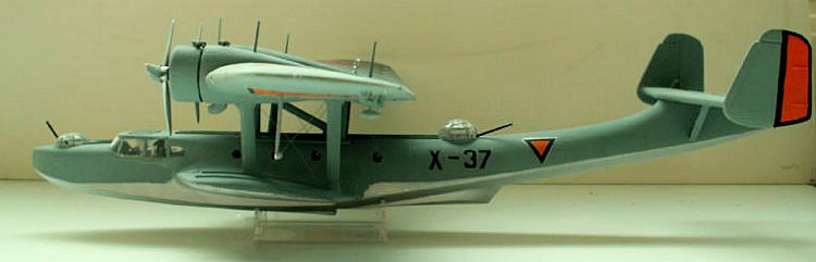
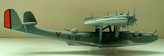
After
September 1939 the roundels were replaced with orange triangles, with in 1/72
scale a 2 mm semi gloss black outline. Also the outsides of the rudders were in
orange with the semi-gloss black outline. Plane numbers in black on the fuselage
sides.
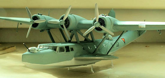
However,
in the East-Indies, the paint schemes were changed. All under surfaces were
painted white, and the top surfaces were painted in dark sea grey. National
insignia orange triangles, and orange outside rudders. Small plane number in
front of the tail. Later on, the national insignia were changed into rectangular
red-white bleu flags, plane number once more in small black markings in front of
the tail.
At the
Dutch Military Aviation Museum a Dornier Do-24 is displayed in this livery.
Decals for this plane are also available at the small museum shop there.
| CONCLUSIONS |
 Well, it
has been a big job, and I’m not looking forward to do it once more. When you
start on making adjustments, you just have to know when to stop…. Of course,
there are some aftermarket sets that can deal with some of the problems, but the
basic shape of the fuselage is not good enough. As said in the first lines, you
can just ignore that, and built the kit straight on. You will have enough fun on
the modelling point of view, and you will have a great looking flying boat when
you’re finished. With all the decal options Italeri supplied in the past, there
might be even one livery that might attract you.
Well, it
has been a big job, and I’m not looking forward to do it once more. When you
start on making adjustments, you just have to know when to stop…. Of course,
there are some aftermarket sets that can deal with some of the problems, but the
basic shape of the fuselage is not good enough. As said in the first lines, you
can just ignore that, and built the kit straight on. You will have enough fun on
the modelling point of view, and you will have a great looking flying boat when
you’re finished. With all the decal options Italeri supplied in the past, there
might be even one livery that might attract you.
| REFERENCES |
May 2009
If you would like your product reviewed fairly and quickly, please contact me or see other details in the Note to Contributors.