Kotare 1/32 Spitfire Va
| KIT #: | K32002 |
| PRICE: | $109.00 |
| DECALS: | Three options |
| REVIEWER: | Otis Goodin |
| NOTES: | Great kit, fun and easy to assemble |
| HISTORY |
 The
Spitfire Mk V (Mark 5) was the most widely produced version of the famous
British Supermarine Spitfire fighter and became the Royal Air Force's
principal fighter during 1941–1942. It was originally intended as a
temporary solution but went on to become one of the most important Spitfire
variants of World War II.
The
Spitfire Mk V (Mark 5) was the most widely produced version of the famous
British Supermarine Spitfire fighter and became the Royal Air Force's
principal fighter during 1941–1942. It was originally intended as a
temporary solution but went on to become one of the most important Spitfire
variants of World War II.
During the Battle of Britain in 1940, the Spitfire Mk I and Mk II were proving increasingly challenged by newer German fighters. The RAF planned to replace them with the more advanced Spitfire Mk III, but the Mk III required significant production changes and was not ready for mass manufacture.
To provide a quicker upgrade, engineers installed the more powerful Rolls-Royce Merlin 45 engine into the existing Spitfire airframe. This created the Spitfire Mk V, which could be produced rapidly using existing production lines. The first aircraft entered service in late 1940 and early 1941.
Main Variants
The Mk V appeared in several versions:
Mk Va – armed with eight .303 Browning machine guns. Only a small number were built.
Mk Vb – carried two 20 mm Hispano cannon and four machine guns; this became the most common early version.
Mk Vc – introduced the "universal" C-wing, allowing different armament combinations and greater flexibility
Specialized versions with clipped wings for low-altitude combat and tropical filters for service in hot climates were also produced.
Combat Service
The Mk V entered frontline RAF service in early 1941 and replaced most Mk I and Mk II Spitfires. During 1941 it generally matched or exceeded the performance of the German Messerschmitt Bf 109F, making it an effective fighter over occupied Europe.
The type served on virtually every major front where the RAF operated, including:
Northwest Europe
The Mediterranean
North Africa
Malta
The Middle East
The Far East
 However,
the appearance of the German Focke-Wulf Fw 190 in late 1941 gave the
Luftwaffe a significant performance advantage. The Mk V was increasingly
outclassed, prompting the development and introduction of the Spitfire Mk
IX, which restored parity.
However,
the appearance of the German Focke-Wulf Fw 190 in late 1941 gave the
Luftwaffe a significant performance advantage. The Mk V was increasingly
outclassed, prompting the development and introduction of the Spitfire Mk
IX, which restored parity.
More than 6,400 fighter versions of the Mk V were built between 1941 and 1943, making it the most-produced individual Spitfire version. It served with over 140 RAF squadrons and was exported to numerous Allied nations.
Although designed as a stopgap measure, the Spitfire Mk V became one of the most successful and influential fighters of the war, bridging the gap between the early Battle of Britain Spitfires and the later high-performance Mk IX and Griffon-powered variants.
| THE KIT |
 Kotare
introduced the Spitfire Mk.Va kit in October 2024. It is now sold out but is
available on the usual sites. As a follow up to their Mk.1a and “Brian Lane”
versions, the Mk. Va is similarly designed and features an outstanding box
art painting by Daryll Legg that is included as a frameable print. In fact,
all the Kotare kits include the box art painting as a frameable print.
Kotare
introduced the Spitfire Mk.Va kit in October 2024. It is now sold out but is
available on the usual sites. As a follow up to their Mk.1a and “Brian Lane”
versions, the Mk. Va is similarly designed and features an outstanding box
art painting by Daryll Legg that is included as a frameable print. In fact,
all the Kotare kits include the box art painting as a frameable print.
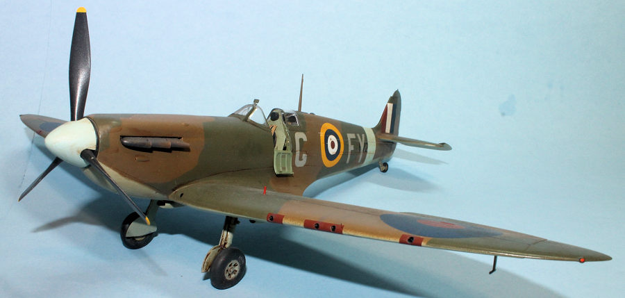
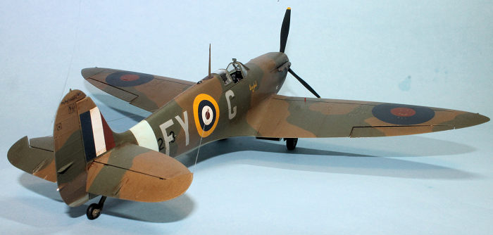
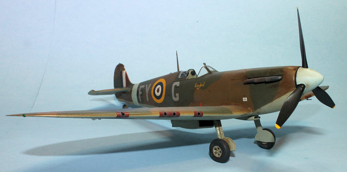
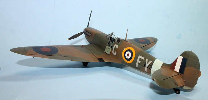
The kit contains 142 injection molded plastic parts, with 40 of them being all new tooled parts. There are options for a pilot’s seat with or without seatbelts molded on. The decals are by Cartograf and include markings for three different Spitfires: (1) Spitfire R7268 “The Swan” with the letters KL-M on the fuselage. This aircraft was flown by several different pilots in June-July 1941. (2) Spitfire W3185, as it appeared in August 1941, “Lord Lloyd I” with the code letters D and B on the fuselage for Squadron Commander Douglas Bader. (3) The Spitfire I chose to build, R7208 FY-G “Liverpool III,” flown by several pilots in the summer of 1941. There is a 28-page instruction booklet with lots of photos of Spitfires for reference.
| CONSTRUCTION |
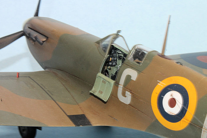
As usual, construction begins in the cockpit, and this one starts at the instrument panel. There is a detailed drawing for placement of the decals on the panel. After painting it, I placed a drop of Future on each instrument so that, when dry, the individual instrument decals could be applied. After they dried, I added another drop of Future to simulate the glass covers. It’s a bit of a tedious process, but the result is worth the effort. The completed instrument panel is attached to the fuselage bottom panel, along with the rudder bar and control tubes, the heelboards, the gun heating ducts, and the rudder pedals. Next the control column and elevator control rod are assembled and attached, along with the radiator flap lever.
 Next up is
the pilot’s seat, and here you have the choice of one with seatbelts molded on,
or one without. I chose without and added seatbelts from HGW. Fuselage frame 11
is then prepared by adding the head rest, armor plate, and voltage regulator on
the back side. The seat is then attached to the completed assembly which is then
placed in the fuselage bottom. Frame 12 is then added to the floorboard behind
frame 11. Kotare recommends that you drill out the lightening holes in the frame
sections for more realism. I only drilled out the most visible ones in frame 11.
Next up is
the pilot’s seat, and here you have the choice of one with seatbelts molded on,
or one without. I chose without and added seatbelts from HGW. Fuselage frame 11
is then prepared by adding the head rest, armor plate, and voltage regulator on
the back side. The seat is then attached to the completed assembly which is then
placed in the fuselage bottom. Frame 12 is then added to the floorboard behind
frame 11. Kotare recommends that you drill out the lightening holes in the frame
sections for more realism. I only drilled out the most visible ones in frame 11.
The previously painted interior fuselage walls are added to each side of the bottom frame. There are several individual parts that must be added to each side, along with decals in several areas on each wall. Frame 13 is added to the fuselage interior assembly, along with a harness for the seatbelts. A few other items are to be added, but at this point not much of it shows on the completed model so you may not want to spend the time and energy to do it. Modeler’s choice.
Detailed instructions for painting the fuselage interior are included, so review this in detail before starting assembly of the interior. There are additional small parts to be added including a raised rivet wireless door, a cine camera footage indicator, a wireless remote controller, the wireless remote contactor (known as the “Pip Squeak”), and the height and airspeed computer.
Once the interior is complete it is added to the port fuselage half along with the propeller shaft. The starboard half is then attached to the port half along with the starboard engine cowling. The fuselage spine is attached to the top of the fuselage, but don’t forget to install the upward facing signal light in the spine before gluing it to the fuselage. I forgot to do this on the Mk.1a kit, and I had to make a do-it-yourself light out of clear cement. It was OK, but the clear plastic part is much better. Anyway, I remembered it this time.
The instructions call for you to cut small squarish holes in the fuel tank cover in which to install station keeping lamp windows. After studying it in detail, I decided I didn’t have the confidence or skill to attempt it, so I left the small windows off. Yes, I was a chicken.
The top and port cowlings are added. If you’re going to do a closed-door option now is the time to attach it. It will require some filling and sanding for a smooth look. I prefer the open door because it shows more of the interior. The stabilizer and elevators are added. Detailed photos are included.
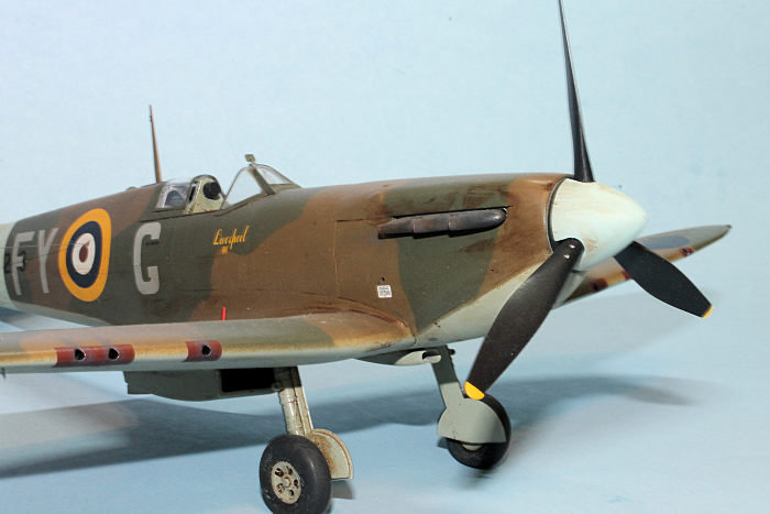 The lower
part of the wing is assembled by installing a spar across most of the wing
bottom. To it are then attached wheel wells. The Browning gun barrels are
installed in the front of the wing at various offset positions. The port and
starboard upper wing sections are then added along with the wing fillets. The
two ailerons are also installed. The radiator and oil cooler are attached to the
bottom of the wings. If you’re careful, you can get away without any filling and
sanding of these two parts.
The lower
part of the wing is assembled by installing a spar across most of the wing
bottom. To it are then attached wheel wells. The Browning gun barrels are
installed in the front of the wing at various offset positions. The port and
starboard upper wing sections are then added along with the wing fillets. The
two ailerons are also installed. The radiator and oil cooler are attached to the
bottom of the wings. If you’re careful, you can get away without any filling and
sanding of these two parts.
Once the wing is finished, it is attached to the fuselage, sliding it rearward per the instructions for a good fit. The oil tank and bottom cowlings are attached to the underside of the very front of the fuselage. Again, detailed photos are provided along the way.
Attention next turns to the undercarriage. Each side is formed with a strut, door and wheels. The struts are designed to fit in the wheel wells at the correct angle, although it may require a little cutting to improve the fit. There’s a detailed drawing on how the struts should fit.
A few remaining details include the prop and spinner, the aerial mast, the rudder, and the undercarriage down indicators which are “up” when the undercarriage is down. I misplaced mine, but I made replacements with plastic rod. The exhaust manifolds were added, and I used the more detailed resin parts included with the kit. They look nice.
The canopy is added next. I used masks from ASK prior to painting; however, I broke the canopy hood before it could be installed, so my Spit is hoodless. There is no rigging from the antenna to the tailfin, but there is some from each stabilizer to the fuselage.
| COLORS & MARKINGS |
I mostly used Vallejo paints from their Battle of Britain series. The instrument panel is painted Black (“Night”), and the bottom frame is painted IDF Green to represent the gray-green called for on most of the interior. A few parts were painted a slightly lighter gray-green such as the control column and pilot seat. There was a lot of variation in shades as colors, interior and exterior, were supplied by numerous sub-contractors or even mixed in the field. Interior frame 11 was painted a green shade on the front half and Aluminum on the back. Frames 12 and 13 were painted in Aluminum. Fuselage walls were painted IDF Green. The various small parts installed on the walls were mostly painted Black.
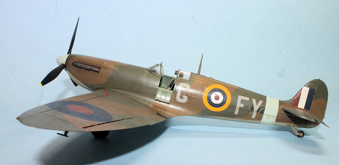 Upper
surfaces were painted in Dark Earth and Dark Green applied with a hard
demarcation line in the “A” camouflage pattern. I used the A Pattern mask
supplied by AMLM. Instead of the Vallejo Dark Green, I used the Tamiya “lighter”
Dark Green, number XF 89. It’s personal preference on which Green or Dark Earth
version you use as there are both dark and light versions of each. The underside
was painted in Sky Type S (for Satin.) The Vallejo color is a pale greenish hue,
although the color ranged from almost white to a light bluish shade known as
Duck Egg Blue. The undercarriage struts and wheel hubs were also painted Sky.
The light blue band around the fuselage and the spinner were each painted Duck
Egg Blue considerably lightened with White. The propeller blades were painted
Black, and exhaust manifolds were painted several colors to represent the
effects of heat. I used Vallejo Gun Metal, Medium Gray, and even Yellow and Red
to produce the look of heated metal. Interestingly, the actual exhaust manifolds
were made from a metal alloy called Inconel, which does not rust, so don’t paint
them as rusted metal.
Upper
surfaces were painted in Dark Earth and Dark Green applied with a hard
demarcation line in the “A” camouflage pattern. I used the A Pattern mask
supplied by AMLM. Instead of the Vallejo Dark Green, I used the Tamiya “lighter”
Dark Green, number XF 89. It’s personal preference on which Green or Dark Earth
version you use as there are both dark and light versions of each. The underside
was painted in Sky Type S (for Satin.) The Vallejo color is a pale greenish hue,
although the color ranged from almost white to a light bluish shade known as
Duck Egg Blue. The undercarriage struts and wheel hubs were also painted Sky.
The light blue band around the fuselage and the spinner were each painted Duck
Egg Blue considerably lightened with White. The propeller blades were painted
Black, and exhaust manifolds were painted several colors to represent the
effects of heat. I used Vallejo Gun Metal, Medium Gray, and even Yellow and Red
to produce the look of heated metal. Interestingly, the actual exhaust manifolds
were made from a metal alloy called Inconel, which does not rust, so don’t paint
them as rusted metal.
I applied a few coats of Future to give the Spitfire a glossy surface for the decals, which all went on with no problem. Once dry, I sprayed a coat of Polly Scale Satin to tone down the gloss. After about three months of off and on building, my Spitfire Mk.Va was finished.
| CONCLUSIONS |
I really enjoyed the build and learned a lot in the process. Highly recommended.
| REFERENCES |
Kotare kit instructions
Wikipedia “Supermarine Spitfire (early Merlin-powered variants)”
27 July 2026
Back to the Previews Index Page
Back to the Previews Index Page