| KIT #: | 00553 |
| PRICE: |
£26.99
(ON SALE) |
| DECALS: | Two kit options |
| REVIEWER: | Torben Plesberg |
| NOTES: | Conversion |
| HISTORY |
My first real aircraft model was the
AVRO Lancaster – the classic Airfix kit. I bought the kit in 1960 for 12
Danish kroner ( roughly = 1,80 USD in the present currency exchange
rate). The kit was assembled and painted in the recommended camouflage scheme.
Humbrol Colors were unknown to me at that time, but I bought some small cans of
paint in the local bicycle shop. I had to mix the colors myself, but I
did not even have a color
photo of a Lancaster as reference, so my shades were purely guess-work. The
paint descriptions ”dark green” and ”dark earth” were my only clues for
mixing the shades. My dark
green turned up to be acceptable, but my dark earth was too brown and too dark.
The model was painted before gluing the wings and tail planes to the fuselage.
This was the easiest way of doing the painting. The sides and bottom surfaces,
spinners, propellers and gear got no paint, as the plastic was already black. I
took some black and white photos of the finished model
and the camouflage pattern was invisible on the model! The colors had
apparently exactly the same black/white value. I was 14 years old and rather
content with the result of my efforts.
When SAAB was working on the development
of the Lansen fighter, STAL
simultaneously was working on the development of a suitable jet engine to be
used in the Lansen. Everybody knows the SAAB company, but only a few knows STAL.
STAL or Svenska Turbinfabriks AB Ljungström was founded in 1913 and was a
specialist on constructing steam turbines for powerplants. The STAL company
delivered in 1932 a very
powerful steam turbine to the Västerås Steam Powerplant. The efficiency
of this turbine exceeded 90%, a world record at that time for efficiency of
steamturbines.
In the late forties STAL began developing gas turbines for jet engines. The
company hoped to get orders from the Flygvapnet. At the same time SAAB was
developing jet aircraft for the Flygvapnet – the Tunnan and the Lansen. And it
is here the Tp 80 gets into the picture: The Flygvapnet needed a flying testbed
for the testing of the STAL Dovern jet engine. Rolls Royce has named their jet
engines after English rivers: Nene, Avon, Spey, Trent etc. STAL named their
product after a small lake in the vicinity of the factory in Finspång, which is
located about 25 kilometers north of Linköping, where the test center of the
Flygvapnet (Fc) is situated at Malmen.
In 1950 the Flygvapnet ordered a Lancaster by AVRO. The plane should be modified
as a flying testbed according to the specifications of the Flygvapnet. AVRO did
their task and the aircraft was delivered in 1951 and was attached to the Fc at
Malmen, and got the designation Tp 80 and the serial number 80001.
 The Fc performed more than 100 flights testing the Dovern engine, however, the
Dovern never completely fulfilled the expectations of the Flygvapnet. The engine
would under certain circumstances suddenly loose the major part of its power –
and this is unacceptable in a military fighter plane. So the big order for jet
engines for the Lansen went to Rolls Royce. The Avon engine was just suitable
for the Lansen production, and later for the Draken. Rolls Royce delivered Avon
engines for the prototypes only, all other engines were licence built by another
well known Swedish company: the Volvo Aero in Trollhättan, Svenska Flygmotor
division.
The Fc performed more than 100 flights testing the Dovern engine, however, the
Dovern never completely fulfilled the expectations of the Flygvapnet. The engine
would under certain circumstances suddenly loose the major part of its power –
and this is unacceptable in a military fighter plane. So the big order for jet
engines for the Lansen went to Rolls Royce. The Avon engine was just suitable
for the Lansen production, and later for the Draken. Rolls Royce delivered Avon
engines for the prototypes only, all other engines were licence built by another
well known Swedish company: the Volvo Aero in Trollhättan, Svenska Flygmotor
division.
The flying tests continued, however, with the Tp 80, but now it was a Swedish
designed afterburner for the Avon engine, which was being tested. Now and then
the Tp 80 also had some completely different tasks, which it was well suited to
do, such as photography of aircraft in the air. The Flygvapnet made a recruiting
movie on the J 33 Venom: Nattjakt (night fighting!). If the casing around the
opening for the tail turret is removed, it leaves a 180 degrees free view
backwards, and the aircraft makes up a perfect platform for a camera operator.
Most of the air scenes were filmed from the tail of the Tp 80.
We are now in 1956, when the test-flights suddenly came to an end. During a
flight with an after-burner engine, the Tp 80 caught fire and crashed in flames.
Unfortunately just 2 of the 4 crew members managed to bale out in time. A sad
end of the Lancaster era in the Flygvapnet!
At last it should be mentioned, that STAL managed to solve all the problems of the Dovern engine, and it turned out to be a successful industrial powerplant. An updated version of the Dovern engine is obtainable even today!
| THE KIT |
Compared to the old Airfix kit from 1958 the Hasegawa kit represents a huge step
towards a realistic model. The
Airfix kit was a toy rather than a scale model. At that time rivets were
compulsory – but hopelessly out of scale. On a close-up photo of the BBMF
Lancaster, I calculated that on the fuselage between the canopy and the bomb bay
door there are approximately 2800 rivets – starboard side only! This area on the
model is roughly 2 by 4 cm, and
this means, that one square cm has 350 rivets. Rivets have nothing to do on
small-scale models. But if we talk of scale 1/16 or even bigger, the rivets may
be realistic.
The Hasegawa kit consists of 275 parts in light grey and clear plastic and
is without rivets. In return there are some screw heads on the engine
cowling parts – and that is OK with me. Recessed panel lines seem to be wanted
by modelers of the 21st century, but has anyone tried to calculate
the scale-correct size of these scratches? They are probably out of scale in the
same way as the rivets were 50 years ago! I would prefer no panel lines at all
for a model to a 1/72 scale. Some modelers even scratch their
 own panel lines.
The effort should rather be to secure the shape of the parts provided and to
what extent optional parts should be used – or not.
own panel lines.
The effort should rather be to secure the shape of the parts provided and to
what extent optional parts should be used – or not.
| CONSTRUCTION |
I shall mainly deal with the necessary operations needed to change the Hasegawa
standard Lancaster Mk.I into the highly specialised Swedish version: the Tp 80.
The changes relate to the fuselage, the fins and the gear. Wings, tail planes
and engines are unchanged.
The opening of the long bomb bay was reinforced by gluing 2 pieces of 3 x 3 mm
ABS strip on the inner sides. And this reinforcement offered furthermore a firm
plane for gluing the new fuselage bottom with t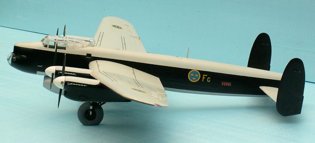 he jet pod in place. A test
assembly of the two fuselage halves revealed, that the plastic piece supposed to
keep the tail planes in place could be moved about one mm sideways. I wanted
this support to be absolutely firm, and I did this by gluing 2 small strips of
0,5 mm ABS on either side of the inner side of the slot. Now the tail plane
support was firm, when the fuselage halves were pressed together.
he jet pod in place. A test
assembly of the two fuselage halves revealed, that the plastic piece supposed to
keep the tail planes in place could be moved about one mm sideways. I wanted
this support to be absolutely firm, and I did this by gluing 2 small strips of
0,5 mm ABS on either side of the inner side of the slot. Now the tail plane
support was firm, when the fuselage halves were pressed together.
The next operation was to make everything which should be done before the final
assembly of the fuselage. This included painting of the interior of the cockpit
area. All the walls should be
interior green (Humbrol no 78) and the furniture and instrument panel flat black
(Humbrol no 33). The decals with instruments and radio were omitted, since they
can´t be seen from the outside anyway. Don`t use effort and time on something
unnecessary! The fuselage was then glued together using K 200 – a fast drying
glue which hardens in 5 minutes. And I could immediately after do the nessessary
filling and sanding – an easy job, because the halves fit so well together.
The assembly of the two fuselage halves demands some careful planning,
especially if you use a fast drying glue. It is a good thing to exercise this
operation 3-5 times without glue – just to learn your fingers exactly what to
to, and do it fast and without failures. And you will know how much tape and
other fastenings you need to make a perfect assembly.
 As the Tp 80 is unarmed the 3 turrets should be omitted and the openings sealed.
In both ends of the fuselage it was necessary to make a casing conformal with
the openings. These were made of
two pieces of Ureol, which were roughly formed and glued in place. The after
casing should be glued to the parts no 11 & 12. The new twin tail wheel should,
however, be in place before the casing is glued on! (I shall deal with
the tail wheels later.)
As the Tp 80 is unarmed the 3 turrets should be omitted and the openings sealed.
In both ends of the fuselage it was necessary to make a casing conformal with
the openings. These were made of
two pieces of Ureol, which were roughly formed and glued in place. The after
casing should be glued to the parts no 11 & 12. The new twin tail wheel should,
however, be in place before the casing is glued on! (I shall deal with
the tail wheels later.)
The final shaping of the two casings was done very carefully using a small
diamond sanding drum with a mini drilling machine. This tool is most useful for
shaping without touching the plastic parts. The openings on the dorsal and the
belly could be closed by optional parts from the kit. Some filling and sanding
was necessary to seal the openings properly.
The new bottom piece of the fuselage, which was to replace the bomb bay doors,
was made of an appropriate piece of Ureol. The shape was made according to
Karlström`s drawing in ”Flygplansritningar 5”. The width was kept 1 mm too much
to ensure a precise matching to the fuselage after being glued in place. The
precise matching was a milling job. And the milling could not have been done
without the 3 x 3 mm reinforcements mentioned earlier, which secured a firm
fixation of the fuselage during the
milling procedure.
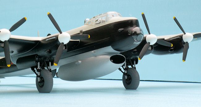
The jet pod.
The jet pod was cut from a piece of
Ureol with the contours from the side and from the bottom. The exhaust pipe
should be made in brass, and was a job for the lathe. The intake was made around
an 8 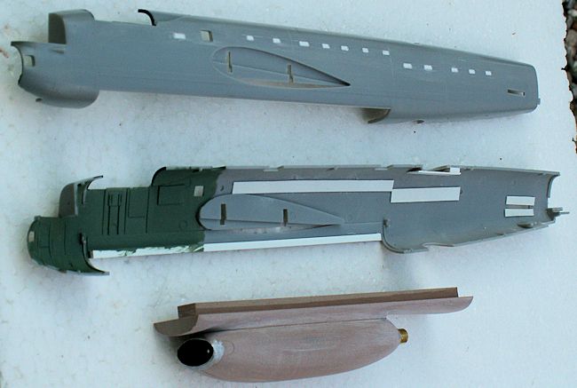 mm hole in the center of the front. The hole was drilled about 3 cm down.
On either side of the 8 mm hole a 4 mm hole was drilled 2 cm down. The material
between the holes was carefully milled away, and the oval F-100 like air intake
was the final result. After the intake was formed, the hole in the hot end was
drilled, also using the 8 mm drill – and only this. The exhaust pipe opening is
circular.
mm hole in the center of the front. The hole was drilled about 3 cm down.
On either side of the 8 mm hole a 4 mm hole was drilled 2 cm down. The material
between the holes was carefully milled away, and the oval F-100 like air intake
was the final result. After the intake was formed, the hole in the hot end was
drilled, also using the 8 mm drill – and only this. The exhaust pipe opening is
circular.
Next the exhaust pipe was turned in brass. I tried first to make it in a mixture
of acryl and brass, but the result was not good enough. All the time you learn
by your mistakes – but mistakes often come before a success! The jet pod was
attached to the new bottom piece by means of a pair of 2 mm brass rods. This
made it possible to separate the parts again for the ultimate adaptation to the
fuselage. And at last I made the front piece of the Dovern engine and pressed it
into the bottom of the intake opening. Now you can see that there is something
inside the jet pod!
At length the final shaping of the jet pod
could be done. All unnecessary material was to be removed – until the
right shape was obtained. As the drawing did not show all of the shape, I used
all available photos of the original Tp 80 as reference. The jet pod was
finished when there was no apparent difference between the model and the
documentation. However, this will not guarantee the model to be 100 % correct! A
model can never be more correct than the documentation allows. The documentation
is - as in this case – often
incomplete. The best documentation will be the photos you take of the object you
want to model. But for very good reasons I did not have this option.
The biggest problem, however,
turned out to be the connection between the bottom and the jet pod. It took
quite some time and numerous disconnections of the jet pod from the bottom to
sand a smooth connection without spoiling the shape of either the jet pod or the
bottom. But at length I was satisfied with the result.
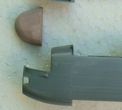
The fins
The fins should be modified to the
Lincoln-type, a rather easy
operation. I simply cut the rear downward corner off and replaced it by a small
ABS plate of the correct thickness. The correct shape was just a matter of
sanding. The finished Lincoln fin was, however, 3 mm too short compared with the
Karlström drawing. Was Hasegawa or Karlström wrong – or both of them? This is a
genuine documentation problem!
I made several measurements on the photos of the real Tp 80 and found, that
Karlström was right. The book ”Lancaster – a bombing legend” contains a lot of
photos of the only two flying Lancasters in the world. I also measured the fins
on all of the head on photos and found that Hasegawa was right! Now the question
was: did the Tp 80 get an especially
prolonged Lincoln fin? I could imagine that it might have been necessary
with extra prolonged fins to secure the stability and manoeuvrebility of this
very special aircraft. The jet pod must have had quite an impact on the flying
characteristics of the Tp 80!
Karlström has a note on his drawing, saying: ” Tp 80 was a modified, unarmed
Lancaster MK.I with bigger Lincoln-type fins and twin tail-wheels.” These words
could be understood thus: The Lancaster had Lincoln-type fins, but they were
taller than normal for this type of fin. I hope that someone with a first or
second hand knowledge of the Tp 80 will enlighten me on this point! Anyway, I
cut the fins in the middle and put in an extra piece of ABS plate to make the
fins 3 mm taller. Some filler and
sanding smoothed out the unavoidable steps from the lengthening.
The tail wheels
An important modification is the tail wheel. It had to be retractable, otherwise
the rubber would be
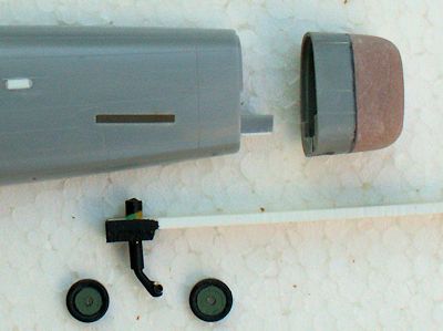 burned by the hot exhaust from the Dovern engine. The rather
big single tail wheel of the Lancaster is not suitable for being made
retractable. AVRO was, however, at that time occupied with the developement of
the Shackleton, and I wonder if the twin tail wheels of this aircraft found
their way to the Tp 80? Anyway, I had to produce two wheels, the leg, the wheel
doors and cut the hole in the fuselage beneath the elevators. And do not
forget a piece of Ureol
glued inside the fuselage in which to fasten the leg. NB: the position of the
retractable twin wheels is about 2 cm aft of the position of the non retractable
big single tail wheel. The wheel doors must be rounded to conform with the
rounded bottom. And the doors
are in a horizontal position,
when they are open.
burned by the hot exhaust from the Dovern engine. The rather
big single tail wheel of the Lancaster is not suitable for being made
retractable. AVRO was, however, at that time occupied with the developement of
the Shackleton, and I wonder if the twin tail wheels of this aircraft found
their way to the Tp 80? Anyway, I had to produce two wheels, the leg, the wheel
doors and cut the hole in the fuselage beneath the elevators. And do not
forget a piece of Ureol
glued inside the fuselage in which to fasten the leg. NB: the position of the
retractable twin wheels is about 2 cm aft of the position of the non retractable
big single tail wheel. The wheel doors must be rounded to conform with the
rounded bottom. And the doors
are in a horizontal position,
when they are open.
And dealing with the gear: Hasegawa`s main wheels were no good for two reasons:
they were a little too small although the diameter is perfect, and they lacked
the pattern. So I went hunting in my unbuilt kits. And in the Airfix Mosquito
1/48 kit I found exactly, what I
was looking for: the main wheels of the Mossie were perfect for the Tp 80, and
with a nice pattern. They were without flat bottom, but it was a piece of cake
to mill off 1,5 mm and put some filler on for the bulging. All tyres were
painted with Model Master ”antracitgrau”.
The gear was not up to the standard of the rest of the kit, and I had to make a
small modification to get it useable. The problem was, how to fix two pointed
ends to each other. I did solve the problem by connecting the ends by a small
piece of thin electric wire insulation. There was no help to get from the
instructions. It seems to me that Hasegawa has totally overlooked the
problem with the gear legs. If the
instructions are good, there will be no doubt of what to do. I had to consult
the gear of my old Airfix Lancaster to realise, how the parts should be put
together. The easy solution of the problem would of course have been: gear up.
The canopy has only the bulged pane in the starboard side. But this was very
easy to make, because the transparent
parts of the kit are very generous and allow several options. The
astrodome should be the taller one, and the
bomb aiming blister should
be the smaller one. Hasegawa has made a small blunder. The escape hatch of the
canopy is placed too far forward. It should be moved one frame backwards. But I
must confess: I did not do that – because I became aware of the problem after
I had painted the canopy.
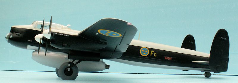
| COLORS & MARKINGS |
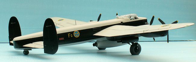
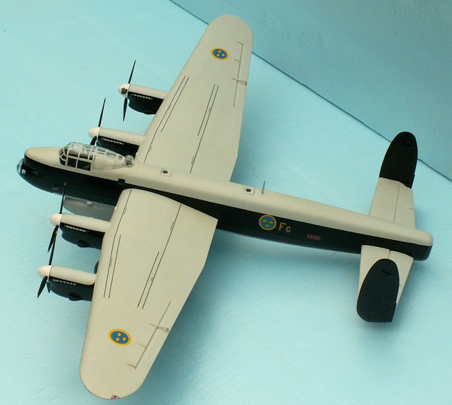
As to the color scheme there are two options: Either metal all over, or light
grey upper surfaces and black bottom surfaces with the jet pod and the fuselage
behind the jet pod kept in natural
metal. I chose the latter option, because I like the contrast between the black
color and the yellow-blue crown markings. The light grey is described as ”medium
sea grey”. I found that Humbrol no 147 light grey would be appropriate
(FS36495). The spinners should be gloss white in both options. The bottom
surfaces were painted gloss black, Revell no 7. The jet pod and the bottom of
the fuselage was painted with natural steel, Xtracolor no x502. Here it should
be mentioned, that all of the bottom plating aft of the jet pod are stainless
steel plates! Steel can better cope
with the heat from the jet engine than aluminium can. All parts of the aircraft
were painted 3 times. Normally I would have primed the model with Humbrol Metal
Cote 27002 polished aluminium. But since I had no documentation for weathering
of the Tp 80, I could save this step. My model depicts the aircraft just after
leaving the paint shop.
natural steel, Xtracolor no x502. Here it should
be mentioned, that all of the bottom plating aft of the jet pod are stainless
steel plates! Steel can better cope
with the heat from the jet engine than aluminium can. All parts of the aircraft
were painted 3 times. Normally I would have primed the model with Humbrol Metal
Cote 27002 polished aluminium. But since I had no documentation for weathering
of the Tp 80, I could save this step. My model depicts the aircraft just after
leaving the paint shop.
 d if the model had been to a 1/48 scale, I would have made the
text in Swedish.
d if the model had been to a 1/48 scale, I would have made the
text in Swedish.
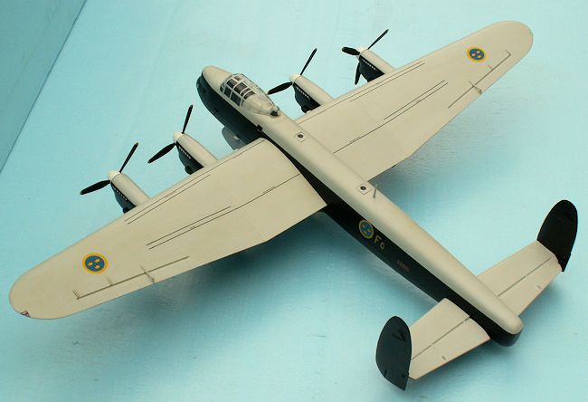
| CONCLUSIONS |
 Almost all of the parts are very precisely
and correctly made, and fit very well together. A proof of this is the
fact that it is not necessary to glue the wings and tail planes to the fuselage.
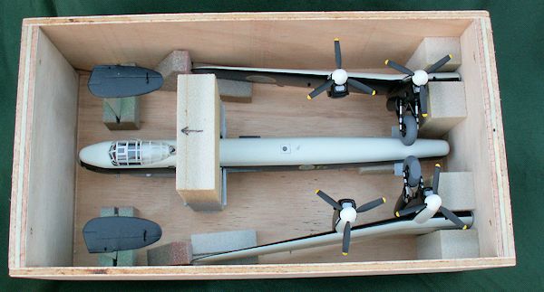
This might be an advantage if you need to transport the model. A much smaller
box is sufficient, as the wings and tail planes can be separated from the
fuselage.
Almost all of the parts are very precisely
and correctly made, and fit very well together. A proof of this is the
fact that it is not necessary to glue the wings and tail planes to the fuselage.
This might be an advantage if you need to transport the model. A much smaller
box is sufficient, as the wings and tail planes can be separated from the
fuselage.
The Hasegawa kit is absolutely highly recommendable -
but other kits not quite to the same high standard
are at much lower prices.
Finally I would mention that I have made a ”Lan-casket” for the safe transport
of my Tp 80 to model exhibitions around. The outer dimensions of
the Lan-casket is 33 by 18 by 12 cm, and it can be handled in any
position including upside down – the model inside is absolutely safe!
| REFERENCES |
Björn Karlström: Flygplanritningar 3 . Allt om Hobby, Stockholm. ISBN
91-85496-25-1
December 2013
If you would like your product reviewed fairly and quickly, please contact the editor or see other details in the Note to Contributors.