ICM 1/32 Gloster Gladiator
| KIT #: | 32040 |
| PRICE: | $65.00 |
| DECALS: | Four options |
| REVIEWER: | John Summerford |
| NOTES: | RB Productions seat harness used |
| HISTORY |
The Gloster Gladiator (or Gloster SS.37) was a British-built biplane fighter. It was used by the Royal Air Force (RAF) and the Fleet Air Arm (FAA) (as the Sea Gladiator variant) and was exported to a number of other air forces during the late 1930s. It was the RAF's last biplane fighter aircraft and was rendered obsolete by newer monoplane designs even as it was being introduced. Though often pitted against more formidable foes during the early days of the Second World War, it acquitted itself reasonably well in combat.
The Gladiator saw action in almost all theatres during the Second World War, with a large number of air forces, some of them on the Axis side. The RAF used it in France, Norway, Greece, the defense of Malta, the Middle East, and the brief Anglo-Iraqi War (during which the Royal Iraqi Air Force was similarly equipped). Other countries deploying the Gladiator included China against Japan, beginning in 1938; Finland (along with Swedish volunteers) against the Soviet Union in the Winter War and the Continuation War; Sweden as a neutral non-combatant (although Swedish volunteers fought for Finland against USSR as stated above); and Norway, Belgium, and Greece resisting Axis invasion of their respective lands.
 The South African pilot Marmaduke "Pat" Pattle was
the top Gladiator ace with 15 victories with the type.
The South African pilot Marmaduke "Pat" Pattle was
the top Gladiator ace with 15 victories with the type.
[Perhaps the most famous Gladiator story is the siege of Malta]
(Courtesy of Wikipedia)
A stock of 18 Sea Gladiators from 802 Naval Air Squadron had been delivered by HMS Glorious, in early 1940. Three were later shipped out to take part in the Norwegian Campaign and another three were sent to Egypt. By April, Malta was in need of fighter protection and it was decided to form a flight of Gladiators at RAF Hal Far, to be composed of RAF and FAA personnel. Several Sea Gladiators were assembled and test-flown. In the siege of Malta in 1940, for ten days the fighter force defending Malta was the Hal Far Fighter Flight, giving rise to a myth that three aircraft, named Faith, Hope and Charity, formed the entire fighter cover of the island. The aircraft names came into use after the battle. More than three aircraft were operational, though not always at the same time; others were used for spare parts. No 1435 Flight, which later assumed control of Malta's air defense, took on the names Faith, Hope and Charity for its aircraft upon its reformation as the air defense unit in the Falkland Islands in 1988.
The Italian air force units deployed against Malta
should have easily defeated the Gladiators but its maneuverability and good
tactics won several engagements, often starting with a dive on
Savoia-Marchetti SM.79 Sparviero bombers before the Fiat CR.42 and Macchi
MC.200 escort fighters could react. On 11 June 1940, a Gladiator damaged a
Macchi and on 23 June, a Gladiator flown by George Burges, managed to shoot
down an MC.200. Another successful pilot over Malta was "Timber" Woods who
managed to shoot down two S.79s and two CR.42s, also claiming a Macchi hit
on 11 June and another S.79 damaged. The Gladiators forced Italian fighters
to escort bombers and reconnaissance aircraft. Although the Regia
 Aeronautica had started with a numerical advantage and air superiority,
during the summer of 1940, the situation was reversed with Hurricanes being
delivered as fast as possible and gradually taking over the island's air
defense.
Aeronautica had started with a numerical advantage and air superiority,
during the summer of 1940, the situation was reversed with Hurricanes being
delivered as fast as possible and gradually taking over the island's air
defense.
By June, two of the Gladiators had crashed and two more were assembled. Charity was shot down on 31 July 1940. Its pilot, Flying Officer Peter Hartley, scrambled at 09.45 with fellow pilots F. F. Taylor and Flight Lieutenant "Timber" Woods, to intercept an SM.79, escorted by nine CR.42s from 23° Gruppo. During a dogfight a CR.42 flown by Serg. Manlio Tarantino shot down Hartley's Gladiator (N5519), badly burning him. Woods shot down Antonio Chiodi, commander of the 75a Squadriglia five miles east of Grand Harbor (he was subsequently awarded a posthumous Medaglia d’Oro al Valor Militare, Italy's highest military award). In May 2009, the remains of Charity and others were the subject of an underwater search by NATO minesweepers. Hope (N5531) was destroyed on the ground by enemy bombing in May 1941. The fuselage of Faith is on display at the National War Museum, Fort St Elmo, Valletta today. The fate of at least five more Gladiators that saw action over Malta is not as well documented.
| THE KIT |
The flimsy box top encloses another top opening sturdy box. All of the part sprues are contained in one bag, plus the decals inserted into the instruction booklet. 130 parts are found on four light gray sprues and one clear sprue.
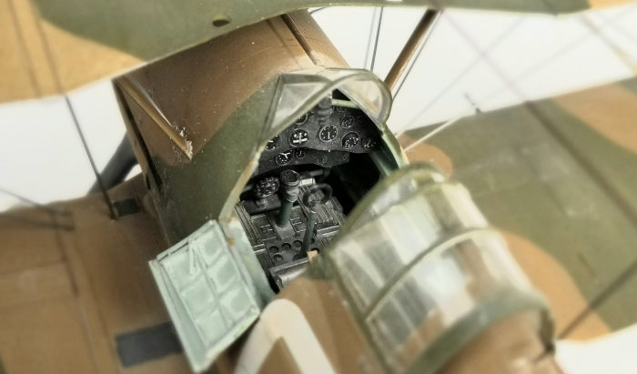
There are not any photo-etch pieces, so a seat harness will have to either be scratch built or sourced from the aftermarket folks. Other than that, the cockpit is well detailed, including fuselage frame tubing. The instrument panel has raised detail decals of individual instruments. There is a choice between opened or closed canopy. The cockpit doors are separate pieces but there are not any tabs or hinges to pose them open. Another choice to make during the build is the location of radio aerial mast on either the fin, or the rudder, depending on which decal markings will be used.
 Four markings are supplied. The first is for a
pre-war silver plane with a blue fin. The second is also a pre-war aircraft
with a standard dark earth and dark green camouflage pattern topside and
white on the underside of the bottom wing and fuselage. The underside of the
top wing is silver. The third option is for an aircraft stationed in Egypt
during 1940 and painted like the second option
Four markings are supplied. The first is for a
pre-war silver plane with a blue fin. The second is also a pre-war aircraft
with a standard dark earth and dark green camouflage pattern topside and
white on the underside of the bottom wing and fuselage. The underside of the
top wing is silver. The third option is for an aircraft stationed in Egypt
during 1940 and painted like the second option
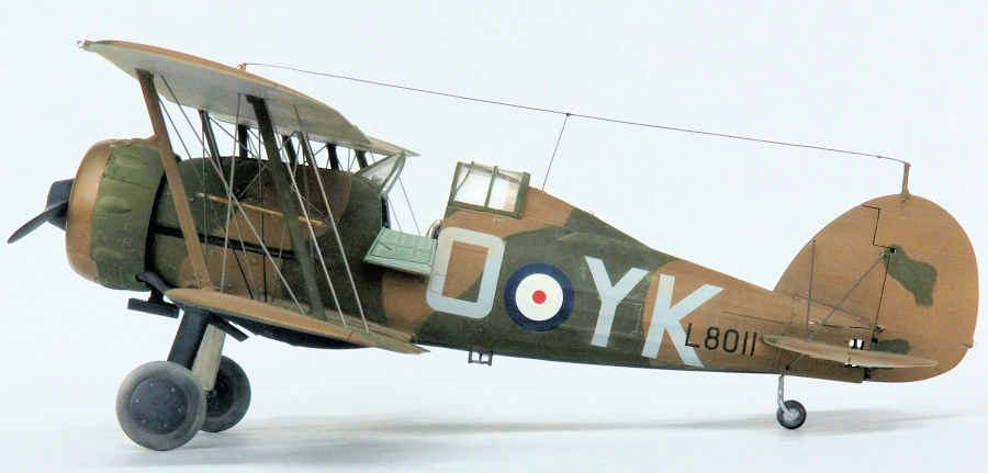
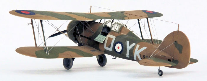
Final decal markings are for the airframe flown by Pattle while a member of No 80 Squadron stationed at Amriya, western Egypt, in early 1940. It too is painted like the war time aircraft with the exception that the port underside is painted flat black and starboard white. This airframe has a simpler aerial rigging arrangement than the other three, however the mast for the wing is not supplied.
A 20-page instruction booklet has a brief description written in Cyrillic and English plus a color call-out chart on the front page. Colors are for Revell and Tamiya paints. The next two pages show the parts map. Building instructions are on the next fourteen pages and comprise 63 steps. The final three pages show the rigging diagrams and painting/decal guides.
| CONSTRUCTION |
As is my usual approach, I started by thinning the plastic behind the rigging points. It would be helpful if dimples were molded at those locations, but the access plates give a good indication of where to work. Holes were then drilled at the approximate angles for the wires. It was at this stage that I noticed that a radio aerial mast for the upper wing is not supplied. I drilled a hole for it when I drilled the holes for the rest of the rigging.
In the first 21 steps the cockpit is built up and
the fuselage is brought together. I started with the instrument panel so
that it would be ready when the instructions call for its installation.
There were three dial decals left over and I didn’t realize that they go on
part # C-20 until it
 was time to cut it from the sprue in step 5. It wasn’t
until I go to step 6 that I realized that part D-37 is shown upside down,
which meant that it didn’t fit properly when installed into the left
fuselage half. I got it to fit properly after some surgery. Because of that
problem, I jumped ahead to steps 15-18 to check the fit when the right
fuselage half is mated to it. The test did not reveal any problems.
was time to cut it from the sprue in step 5. It wasn’t
until I go to step 6 that I realized that part D-37 is shown upside down,
which meant that it didn’t fit properly when installed into the left
fuselage half. I got it to fit properly after some surgery. Because of that
problem, I jumped ahead to steps 15-18 to check the fit when the right
fuselage half is mated to it. The test did not reveal any problems.
I added parts of the seat harness from RB Productions to the cockpit and finished up the fuselage. Everything fit fine and there was just a little bit of clean-up work after the halves were joined. I also glued on the bottom plate where, if this was a Sea Gladiator, the tail hook would be, and addressed that seam.
The tail feathers went on without any fuss. I noticed in many of the phots I viewed that the elevators rest slightly deflected up instead of drooping, so I glued them in place as such and made sure the control stick was back a little bit.
In the next step, close attention must be paid as to which aerial mast that is present must be REMOVED. Double check by referring to the painting illustration of the version that is being built. It is easy to think that the icons indicate which mast to ADD.
The next step includes closing up the cockpit. All of the photos that I viewed of African based Gladiators on the ground with the canopy open and at least one of the doors down so I skipped ahead and assembled the lower wing and offered it up to the fuselage, and then assembled the upper wing. The rear canopy and windshield were glued in place and the doors and sliding canopy were tacked in place. Before moving to the painting stage, the sockets for the struts, landing gear legs and wing pods were masked.
| COLORS & MARKINGS |
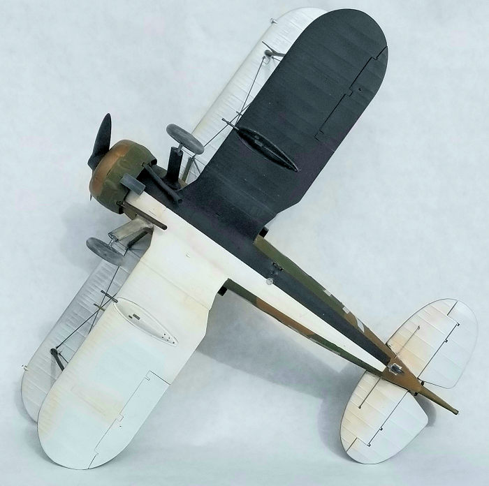 I decided on modeling Pattle’s plane. A coat of
white primer was applied and then acrylic aluminum straight from the bottle
was sprayed on the underside of the top wing and the underside of the
stab/elevator. Black acrylic was applied to the under-port side and white
acrylic to the starboard. After the bottom surfaces were masked, I had
enamel flat dark earth in the paint rack and used that. The earth was masked
and flat dark green applied.
I decided on modeling Pattle’s plane. A coat of
white primer was applied and then acrylic aluminum straight from the bottle
was sprayed on the underside of the top wing and the underside of the
stab/elevator. Black acrylic was applied to the under-port side and white
acrylic to the starboard. After the bottom surfaces were masked, I had
enamel flat dark earth in the paint rack and used that. The earth was masked
and flat dark green applied.
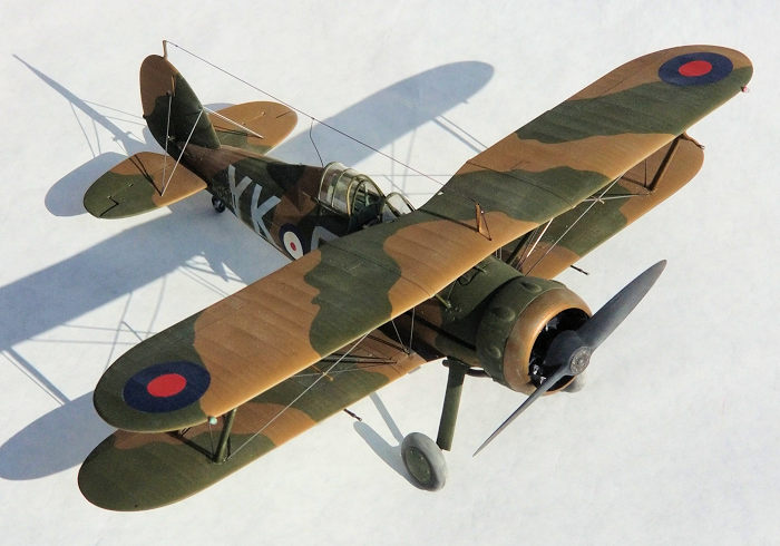
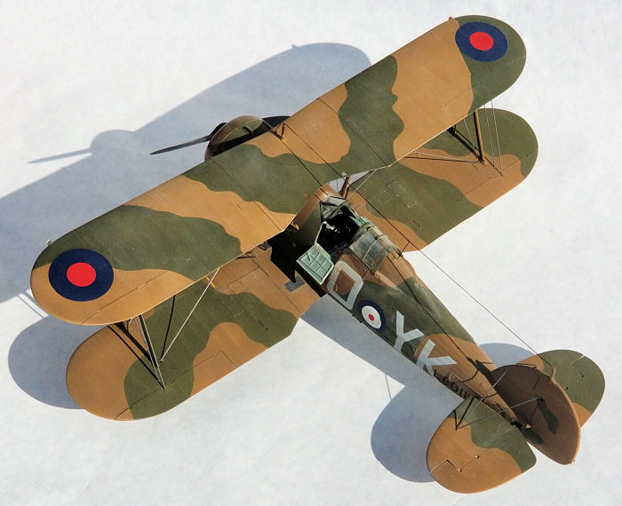
Photos show that the desert aircraft accumulated a lot of dust and were subject to fading, so after unmasking, I rubbed various light powders all over the airframe. A coat of clear gloss was sprayed over the decal areas to ensure their proper adhesion.
I found the decals to be a bit flimsy and easy to fold over themselves. One might consider trimming the clear film from the squadron letters.
When the decals were dry, a coat of clear flat was brushed over them, followed by an airbrushed coat. Another round of dusting was done, making sure the decals looked faded and the entire airframe generally dirty. Another light coat of clear flat was sprayed to seal in the dust.
| FINAL CONSTRUCTION |
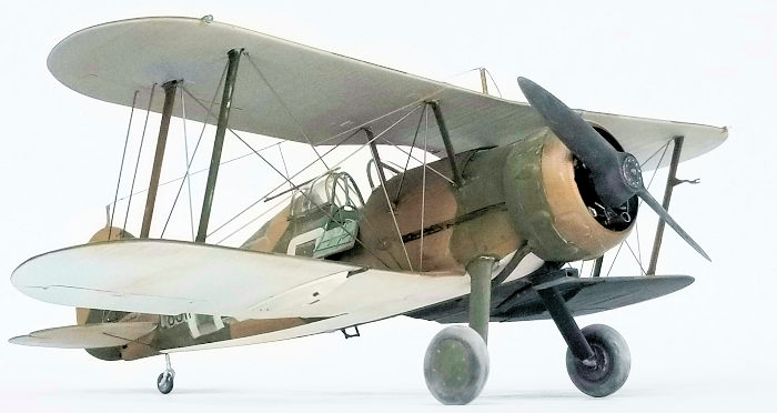
While paint was curing, I worked on the landing gear and engine. When I built up the gear, I discovered the axles are numbered in reverse from the instructions versus the sprue. Fortunately, it’s not much of an issue. I did find an issue with the engine cylinder pieces. They are not keyed to make them idiot proof and this idiot got it wrong. It makes a difference how the front and back sides mate up. I did not glue them together properly and I had to deduce how the reduction gear in the front line up with the intake manifold/blast tube mount in the back. The way to avoid the issue is to glue the manifold to the backside of the cylinders, glue everything to the frontside of the cylinders, and then glue cylinders together.
Mo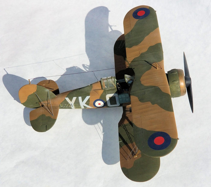 ving on to the cowl, there are two major types
A) for the first three airframe options, or B) the fourth option, the Pattle
aircraft. The instructions don’t clarify that, not do they sperate the
different parts for each option. As I was figuring it all out, I told my
sweetheart, “if you hear any swearing, ignore it”. Fortunately, I was able
to remain quiet. A notch in the lower rear cowl is needed to make room for
the dust filter, and I deduced that I needed to use parts B-1 and B-3, which
are noted for the other options. I taped the three rear cowl pieces to the
front ring and then did test fits of the engine to fuselage and the exhaust
pipes. It took a little fit of filing to the engine to fit and I ended up
removing most of the plastic on parts D-21 and D-22 on the exhaust pipes to
get them to fit. The engineering and instructions in this area leave me
mystified.
ving on to the cowl, there are two major types
A) for the first three airframe options, or B) the fourth option, the Pattle
aircraft. The instructions don’t clarify that, not do they sperate the
different parts for each option. As I was figuring it all out, I told my
sweetheart, “if you hear any swearing, ignore it”. Fortunately, I was able
to remain quiet. A notch in the lower rear cowl is needed to make room for
the dust filter, and I deduced that I needed to use parts B-1 and B-3, which
are noted for the other options. I taped the three rear cowl pieces to the
front ring and then did test fits of the engine to fuselage and the exhaust
pipes. It took a little fit of filing to the engine to fit and I ended up
removing most of the plastic on parts D-21 and D-22 on the exhaust pipes to
get them to fit. The engineering and instructions in this area leave me
mystified.
I moved on to perhaps the most nerve-wracking step—attaching the upper wing. A three-view drawing is very helpful but not supplied. Establishing the forward rake of the cabane struts is difficult due to the amount of play in the sockets in the fuselage. Before the liquid cement fully cured, the upper wing was attached to the cabane struts, followed by a pause, then the interplane struts. I encountered a slight twist and used a pair of tall bottles as a jig to align the upper wing trailing edge with the lower wing trailing edge. After the glue cured, I found that the front port cabane was too short, so I used some tape to force the upper wing to make full contact and let it sit overnight.
Rigging was done with .015 steel wire. I used a pair of dividers to determine the lengths of each wire and used superglue to secure them in place. A length of plastic rod was used as a spreader bar and glued in place with the model up-side down.
 Before gluing the engine to the nose, I noticed a
bit of play in the keyed mount, so again, I placed the model upside-down to
use the exhaust covers and filter mount stub as references to line up the
cylinders. Satisfied, I added the exhaust pipes, followed by the cowl
panels. It took some filing and pressure to coax these parts into place
probably due to my miss-aligning the cylinders earlier. The dust filter came
next followed by the landing gear. I broke an axle on one wheel and pinned
it back on plus reinforced both ends of the axles with a smear of super
glue. The final bits to glue onto the underside were the guns, fuselage
light, and foot step.
Before gluing the engine to the nose, I noticed a
bit of play in the keyed mount, so again, I placed the model upside-down to
use the exhaust covers and filter mount stub as references to line up the
cylinders. Satisfied, I added the exhaust pipes, followed by the cowl
panels. It took some filing and pressure to coax these parts into place
probably due to my miss-aligning the cylinders earlier. The dust filter came
next followed by the landing gear. I broke an axle on one wheel and pinned
it back on plus reinforced both ends of the axles with a smear of super
glue. The final bits to glue onto the underside were the guns, fuselage
light, and foot step.
After flipping the model onto the wheels, all that was left to install were the doors, canopy, navigation lights, radio aerial and propeller. The mast on the rudder broke off, so added new one made from a bit of steel wire, as well as the one for the wing. The aerial is a combination of .012 monofilament thread (used for stringing bead necklaces) strung fore and aft and a length of copper wire with a hook at the top to drape on the main line.
| CONCLUSIONS |
I’m sure there will be a Mark II version as well as a Sea Gladiator release. Aftermarket parts and decals are starting to appear. Other than seatbelts, I don’t see a need for parts, but markings for other air forces are great alternatives. I like the detail provided and parts breakdown, but dislike the instructions for the engine and the way exhaust pipes and cowl go together. Regardless, the engine looks great.
Biplane builds tend to take longer because of the need to install rigging and this one was no exception. I spent close to 40 hours on this project, a lot of that time spent on painting and weathering and I am quite satisfied with my effort.
| REFERENCES |
I made extensive use of the book by Alex Crawford,
Gloster Gladiator vol. 1 Development and Operational History published for
Mushroom Models, ISBN 978-83-89450-59-3. There is a photo included of
Pattle’s aircraft taken shortly before it was handed over to the Greek air
force.
Copyright ModelingMadness.com If you would like your product reviewed fairly and
fairly quickly, please
contact
the editor or see other details in the
Note to
Contributors.