| KIT #: | 408 |
| PRICE: | $37.00 from Hannants |
| DECALS: | Five options |
| REVIEWER: | Patrick Earing |
| NOTES: | Included for this build are the Extra Tech etched metal set ($14.00), Rob Taurus vacuformed canopy ($4.50), and Max Decals set #4821 Irish Air Corps 1922-1956 ($24.75). |
| HISTORY |
I
have been building Irish aircraft all year, ostensibly as a way to get out of a
building rut and expand my knowledge base about different aircraft; but, also as
a salute to 90 years of the Irish Air Corps.
The Gloster Gladiator is a legitimately famous aircraft but one I
would never otherwise have built and displayed because of my Navy centric
modeling view.
However, even an avid USN modeler such as I knows of the wartime escapades
the Gladiator participated in on the desert and arctic fronts of WW II.
Because of its fame, the Gladiator was a shoe-in for the IAC builds,
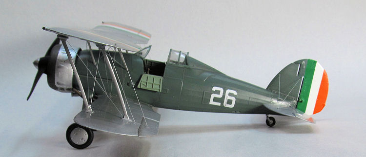
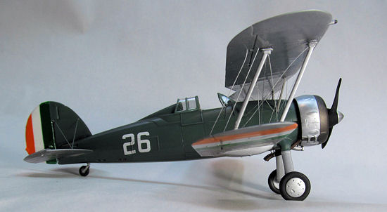
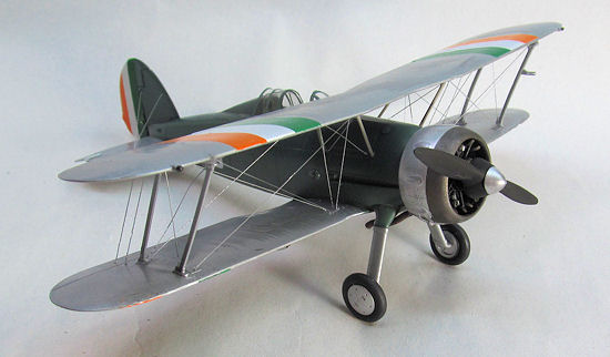
especially in the sexy green and silver early IAC scheme.
 The Irish
Air Corp received its first of four Gladiator Mk I’s in 1938.
These aircraft came directly from Gloster without any radios or
armament. The
purchases did include training for mechanics from both Gloster and Bristol on
how to maintain and repair the aircraft and engines.
Over the next few years the IAC attempted to acquire an additional
eight aircraft, but due to production over commitment and wartime embargos these
aircraft were never delivered.
The Irish
Air Corp received its first of four Gladiator Mk I’s in 1938.
These aircraft came directly from Gloster without any radios or
armament. The
purchases did include training for mechanics from both Gloster and Bristol on
how to maintain and repair the aircraft and engines.
Over the next few years the IAC attempted to acquire an additional
eight aircraft, but due to production over commitment and wartime embargos these
aircraft were never delivered.
Prior to the outbreak of
the ‘Great Emergency’ the four IAC Gladiators were used primarily as advanced
trainers teaching IAC pilots the skills of formation flying, aerobatics, air
combat and ground attack tactics. After the outbreak of war the Gladiators were
operated in an initial role as interceptors for allied and axis aircraft
overflying the Island.
Unfortunately, the Gladiators were outmatched by these more modern
aircraft and the Gladiators were soon withdrawn and used for meteorological
reconnaissance and border patrols.
Eventually, once Hawker Hurricanes were procured by the IAC, the Gladiators
were withdrawn from service and by 1943 they were no longer being actively
flown. The
last IAC Gladiator was written off and scrapped in early 1944 ending the tenure
of the type with the IAC.
| THE KIT |
 This kit
has already been reviewed here at Modeling Madness by Tom Cleaver and I cannot
add anything meaningful to his assessment, so
look here
for a comprehensive outline of what’s in the box.
This kit
has already been reviewed here at Modeling Madness by Tom Cleaver and I cannot
add anything meaningful to his assessment, so
look here
for a comprehensive outline of what’s in the box.
Although a perfectly adequate model can be achieved out of the box, I chose to add some aftermarket embellishments to this build with an Extra Tech etched metal set, Rob Taurus canopy and Max Decals markings for Gladiator number 26 of the Irish Air Corps.
| CONSTRUCTION |
Continuing
with my yearlong build of aircraft of the Irish Air Corps I present the Gloster
Gladiator as used by the Irish Air Corps starting in1938.
This kit is the Mk I boxing of Roden’s Gladiator, and despite some of
the negative press I have read regarding the kit I found it to be a quick and
satisfying build.
 In a twist
on the usual construction sequence, Roden has the modeler begin construction
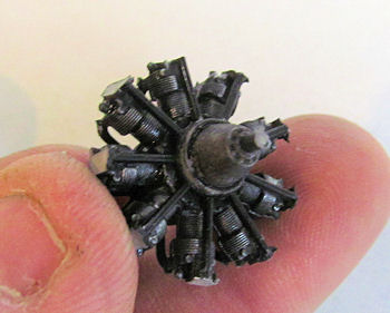
with the engine.
A very good representation of the Bristol Mercury engine is provided by the
kit parts and with little work an excellent model can be created with what is
found in the kit.
The only etch substitutions used from the Extra Tech set were the
front “wiring” triangle at the very front of the engine and the screens for the
vent tubes.
The engine parts were sprayed with Floquile Engine Black and the crank case a
random grey color.
I left off all of the exhaust collector tubes, parts numbered 55C,
until after I installed the engine into the cowling.
Next I assembled the cowling using Tenex and it set aside to dry.
The cowling was the only area I had doubts about, stemming from
previous build reviews I had read, but in the end it isn’t too hard to get a
good result from the kit item.
Some seam cleanup is required as well as restoration of the panel
lines on the cowling, but otherwise the look is right and it fit the engine just
fine.
In a twist
on the usual construction sequence, Roden has the modeler begin construction
with the engine.
A very good representation of the Bristol Mercury engine is provided by the
kit parts and with little work an excellent model can be created with what is
found in the kit.
The only etch substitutions used from the Extra Tech set were the
front “wiring” triangle at the very front of the engine and the screens for the
vent tubes.
The engine parts were sprayed with Floquile Engine Black and the crank case a
random grey color.
I left off all of the exhaust collector tubes, parts numbered 55C,
until after I installed the engine into the cowling.
Next I assembled the cowling using Tenex and it set aside to dry.
The cowling was the only area I had doubts about, stemming from
previous build reviews I had read, but in the end it isn’t too hard to get a
good result from the kit item.
Some seam cleanup is required as well as restoration of the panel
lines on the cowling, but otherwise the look is right and it fit the engine just
fine.
After some primer and
final sand with 400 grit sand paper, things looked good so I painted the
cowling, starting with the burnt metal of the exhaust collector.
This paint I used consists of a custom mix I created several years
back and have since forgotten the ratios of…and I am nearly out of!
Once this was fully dry, I masked the forward section of the cowling
off inside and out using Tamiya tape.
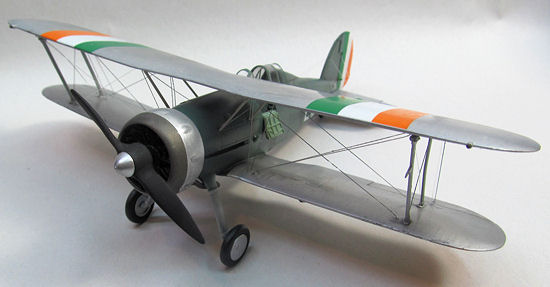
Images of the actual IAC aircraft show that the engine ring and
spinner are a highly polished natural metal.
Trying to replicate this I painted both in Floquil Engine Black
followed with a very wet coat of Testors Glosscoat lacquer.
Before the gloss coat was completely dry, but tacky enough to handle,
I applied RubnBuff silver to each and spread it lightly for coverage.
After about five or so minutes I polished the items out to a good
shine with some baby diaper flannel material.
Overall the outcome was positive; it looks like polished aluminum,
including the slightly hazy look of the real thing in certain light.
Although I had hoped for a bit more shine it looks very convincing.
With the cowling painted I installed the engine into the cowling
securing it to part 56B-making sure that the alignment was correct in terms of
orientation,
 and would
fit the fuselage correctly.
This is a tricky job as there are no alignment pins and the back plate
only goes one way; so, you must pay close attention to orientation of the
cylinder heads as the glue sets for proper placement/orientation to the
fuselage.
Next I trimmed all the exhaust stubs to fit and installed them inside the
cowling from the front-time consuming to say the least.
Done with the engine I turned my attention to the cockpit area.
and would
fit the fuselage correctly.
This is a tricky job as there are no alignment pins and the back plate
only goes one way; so, you must pay close attention to orientation of the
cylinder heads as the glue sets for proper placement/orientation to the
fuselage.
Next I trimmed all the exhaust stubs to fit and installed them inside the
cowling from the front-time consuming to say the least.
Done with the engine I turned my attention to the cockpit area.
I began here by painting
all of the appropriate parts with Model Master RAF Interior Green enamel and
letting things dry.
I substituted the kit seat with a nice resin bit I had in the parts
bin and began assembly per the instructions.
I used only a small portion of the parts provided for the interior
area by Extra Tech, but I will stress that the parts for the radio compartment
behind the seat add considerably to the ‘look’ of that area.
Once detail painting was finished I slightly weathered the cockpit
area using burnt umber and dark grey pastels.
Now it was time to install the ‘tub’ and button the fuselage together.
Roden has not done a great job making it clear where the cockpit floor
should or should not be mounted in the fore and aft plane inside the fuselage
halves, nor do the parts provided for mounting the tub fit for width causing
problems with fitting the fuselage halves together properly.
Additionally, these six small contact points do not provide much in
the way of gluing surface area and I eventually broke then off with all my
considerable fiddling, cutting and frustration.
I creating my own mounts from scraps of Evergreen plastic glued to the
bottom of the floor extending out each side approximately 1/8th inch.
Once I had the cockpit problems sorted out and installed I glued the
fuselage together with Tenex.
 Next I
cleaned up the lower wings and horizontal stabilizers and installed those using
liberal amounts of Tenex.
I can say that everything up to this point on the outside of the kit
fit fantastic with no filler necessary.
I installed all of the flying surfaces except the rudder at this time
as well, posing some for a more ‘dynamic’ appearance.
After a first coat of primer on the seam work I decided to install the
main landing gear legs.
These did not fit well at all and required numerous test fits, cutting
and fiddling to achieve an okay fit.
Filler was used here to smooth things out on the bottom side as well
as to fill the sizable sink marks left in the parts.
Attaching the gun pods to the lower wings rounded out the assemble
portion of the build; now it was time to start considering all the rigging.
Next I
cleaned up the lower wings and horizontal stabilizers and installed those using
liberal amounts of Tenex.
I can say that everything up to this point on the outside of the kit
fit fantastic with no filler necessary.
I installed all of the flying surfaces except the rudder at this time
as well, posing some for a more ‘dynamic’ appearance.
After a first coat of primer on the seam work I decided to install the
main landing gear legs.
These did not fit well at all and required numerous test fits, cutting
and fiddling to achieve an okay fit.
Filler was used here to smooth things out on the bottom side as well
as to fill the sizable sink marks left in the parts.
Attaching the gun pods to the lower wings rounded out the assemble
portion of the build; now it was time to start considering all the rigging.
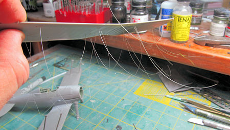
Using a number 65 drill bit I drilled out all of the wire mounting locations top, bottom and fuselage. These holes were drilled approximately 1mm deep. On the underside of the top wing I installed all of the rigging wires using .007 fishing line. Trust me, next time I will do this AFTER painting the wing, as trying to keep all those fine strings out of the wet paint during the painting process was nearly impossible! Once satisfied that I had the rigging sorted out I began to prepare for paint.
| COLORS & MARKINGS |
Priming
commenced in earnest with sanding and reapplications on all of the seams and
filler work areas.
Finishing up took a couple of applications of primer on the bottom of
the fuselage and the landing gear leg areas.
Final sanding was accomplished with 400 grit sand paper and all of the
underside area was re-scribed with an Olfa P cutter and pin vise.
I installed the clear fore and aft sections of the canopy, masked them
up with Tamiya tape and sent it to the paint shop.
As I had chosen to model
the early scheme for Gladiator #26 I needed to create a medium green color for
the fuselage.
To start I used a bottle of Testors RAF Interior green, cut five to three
with flat white and thinned with Testors universal thinner about 50%.
Because of the way I was going to have to mask between colors I
decided to spray the silver first. Using Floquil Engine Black, panel lin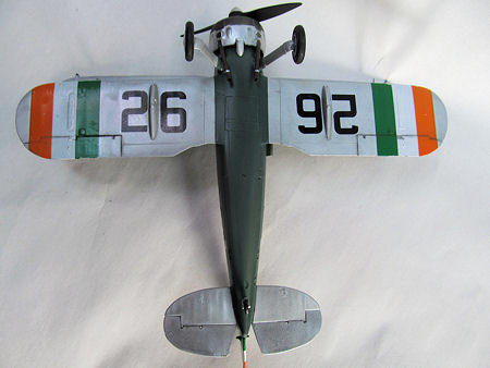 es
and shadow areas were preshaded and then the lower wing, upper wing and tail
assemblies were sprayed with Floquil Bright Silver.
Once things had dried for a day or two I masked the wings and tail and
sprayed the fuselage with my custom mixed green.
When the paint had dried to a tack, I unmasked everything and sprayed
the entire model with Testors Glosscoat lacquer.
es
and shadow areas were preshaded and then the lower wing, upper wing and tail
assemblies were sprayed with Floquil Bright Silver.
Once things had dried for a day or two I masked the wings and tail and
sprayed the fuselage with my custom mixed green.
When the paint had dried to a tack, I unmasked everything and sprayed
the entire model with Testors Glosscoat lacquer.
Max Decals provide two
sets of markings for this aircraft-one in a three tone camouflage s carried
during the ‘Emergency’ and the other the prewar green and silver scheme.
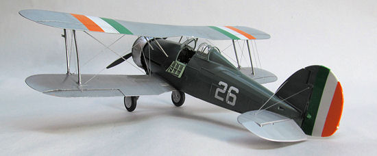
Not much in the way of markings is carried by the early aircraft, call
numbers on the side of the fuselage and under the wings; and some large
tricolored stripes on the top and bottom of the wings and tail.
The call numbers presented no problems and settled down tight with
MicroSol. The
wing stripes were more difficult in that they needed to be trimmed close prior
to application and the orange needs to be on the correct side (outside on both
sides) top and bottom… needless to say I burned some stripe material cutting
them wrong (more than once!)
Max Decals do not provide appropriately spaced tail decals, so I
trimmed some of the mistakes to make theses stripes.
I measured the total width of the rudder at its widest point and
divided by three to get the appropriate widths, but because of the shape it
still took some careful trimming to get the lines straight and widths
consistent. I
would suggest that including these as premade decals would be not only a time
saver, but help newer modelers achieve a successful scheme using this set of
decals.
Once everything had a few days to dry and set I wiped the model down with a damp towel to clean any excess decals solution, tacked it off with a tack cloth and sprayed a final coat of Glosscoat and set it aside for a week to dry.
| CONSTRUCTION CONTINUES |
 Now for
the fun-rigging.
After a week of stalling I attached the outer struts to the lower
wings and steeled myself for the project ahead-making a jig to hold the
mess!
Now for
the fun-rigging.
After a week of stalling I attached the outer struts to the lower
wings and steeled myself for the project ahead-making a jig to hold the
mess!
First things first, I
perused the internet and EBay to see what others had available for sale in the
category of a biplane jig.
Not much came to light, but I did get some ideas about what I might
want mine to look like so I sat down and drafted some plans.
The next day I headed out to the wood shop and began cutting wood for
my own version of a biplane jig. I used western big leaf maple cut ¾ inch thick
and ¼ inch wide.
The base measures 12 ½ inches by 8 inches and is comprised of tennoned maple
strips ¼ inch at the narrowest and 1 inch wood glued of with Tite Bond III.
The slots are offset ¼ and 1 inch to allow for almost infinite spacing
for the uprights (the wider 1 inch spaces allowing tightening of the adjustment
nuts.) The
uprights are ¾ by ¾ inch and 12 inches tall; again slotted for the attachment of
the four adjustable arms.
The arms are 10 inches long and ¼ by ¾ maple.
All of the skinny ¼ thick parts have a 3/16 inch slot running to
within ¼ inch of the end for sliding and adjustment.
The finish on the wood is just a simple application of tung oil.
The brass fittings set me back about $70 and numerous trips to the
hardware store to get the correct bits to do the job.
Ultimately, th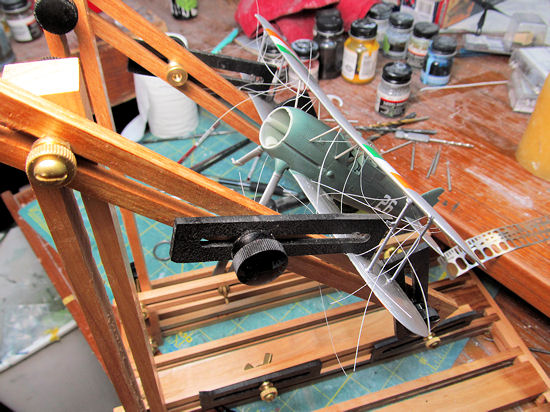 e
biggest problem encountered, and most time intensive to solve revolved around
how to make a jig to cut consistent slots for the multi length strips of ¾ by ¼
maple.
e
biggest problem encountered, and most time intensive to solve revolved around
how to make a jig to cut consistent slots for the multi length strips of ¾ by ¼
maple.
The biplane jig took me
about 30 hours start to finish with some R and D time; remaking of a few parts
and manufacturing my own adjustable ‘finger’ tines from plastic for the arms.
Ease of use and implementation?
Priceless!
On to the rigging!
With the plane securely mounted in my jig I attached the upper wing to
the two outer sets of struts with thin CA glue.
Then using tweezers I carefully set into place the four inner struts
at the fuselage.
With the wing safely attached I began the slow process of trimming and gluing
all of the rigging lines.
This took me about 6 hours over the course of a week to finish. Once a
section was installed and solidly glued I used the glowing bud of a wooden match
to shrink the line into place.
This works okay, but I did have a couple of lines that had to be
replaced as I got too close and ‘cut’ them with the heat.
Additionally, I had at least two lines over tension and begin crushing
the struts-GADS!
Next time I will try a hair dryer as this was suggested to me after the fact
as a good alternative for quickly and safely tightening rigging lines.
Finished with the
rigging I attached the wheels, tail wheel and propeller.
The exhaust was drilled out for scale appearance and was painted with
Testors Metalizer gunmetal, weathered with Rustall and installed with CA glue.
Finally, I attached the rudder and canopy and set it on the shelf.
| CONCLUSIONS |
Overall I am impressed with this kit. It was fun and relatively trouble free to build. I can say that it looks fantastic with all the rigging and now that I have a jig I think there are a couple other Irish biplanes that need to be finished up for this year’s presentation!
| REFERENCES |
 Maxwell,
Joe and Patrick Cummins.
The Irish Air Corps: An Illustrated Guide.
Max Decals Publications, Ltd., Ireland.
2009.
Maxwell,
Joe and Patrick Cummins.
The Irish Air Corps: An Illustrated Guide.
Max Decals Publications, Ltd., Ireland.
2009.
December 2012
Thanks to
for the preview kit. You can find this kit at your favorite hobby shop
or on-line retailer.
If you would like your product reviewed fairly and fairly quickly, please
contact the editor or see other details in the
Note to
Contributors.