| KIT #: | ? |
| PRICE: | 16 pounds sterling |
| DECALS: | One option |
| REVIEWER: | Carmel J. Attard |
| NOTES: | Limited run multi-media kit |
| HISTORY |
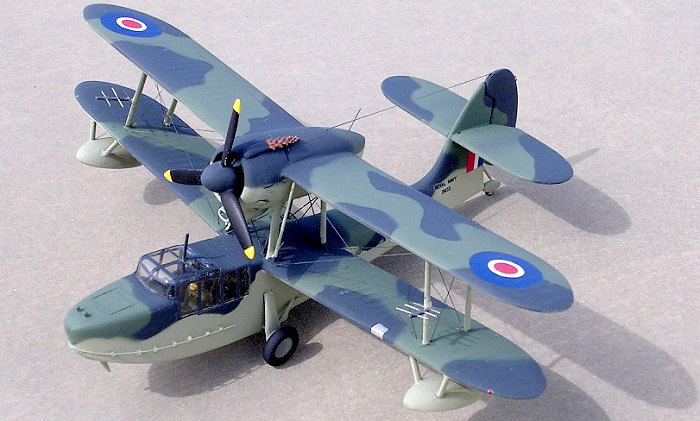
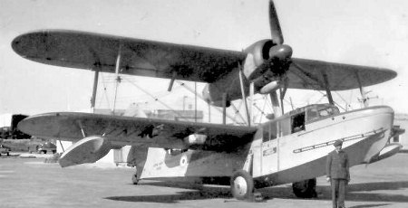
The Sea
Otter was the last seaplane to be designed by Supermarine Company. It was
developed with a view to provide a replacement for the then ageing Walrus
amphibian that gave a stalwart service since mid 30s. It had to wait until later
years of WWII for the Sea Otter to enter service. The visible difference between
the two types was the tracker engine carried above the wings rather than the
pusher propeller. The Sea Otter was
powered by a Bristol Mercury radial engine, which gave a trust of 870 HP. The
 range
was of 833 miles and was greater than that of the Walrus. The Sea Otter had a
span of 46ft and could attain a maximum speed of 163mph and carried an armament
of 3x7.7mm machine guns and a crew of four. It had a range of 833 miles and a
service ceiling of 16,076 feet. The empty weight was 6,805 lbs and when fully
loaded 10,000 lbs.
range
was of 833 miles and was greater than that of the Walrus. The Sea Otter had a
span of 46ft and could attain a maximum speed of 163mph and carried an armament
of 3x7.7mm machine guns and a crew of four. It had a range of 833 miles and a
service ceiling of 16,076 feet. The empty weight was 6,805 lbs and when fully
loaded 10,000 lbs.
 Attaché. Others were
purchased by the colonial service of France, six in number for use in the
Indo-China war.
Attaché. Others were
purchased by the colonial service of France, six in number for use in the
Indo-China war. | THE KIT |
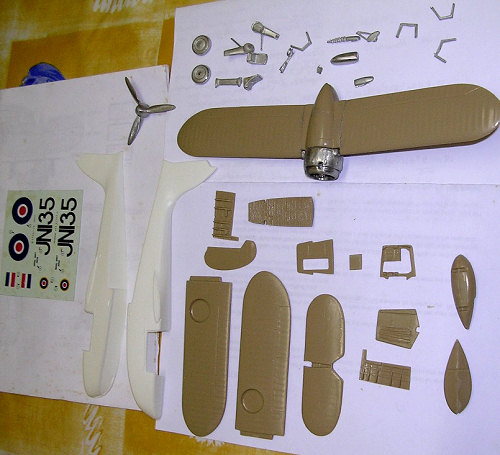 The
kit of the Sea Otter II by Aeroclub was released on the market over 10 years ago
and till now was the only kit of the type that is available on the market. This
is a limited run type moulded in tan plastic, wing and float parts; and having a
vacform fuselage and cockpit canopy as well as detail metal parts. A good decal
sheet is also provided. The kit comes in a typical Aeroclub sturdy box having a
somewhat poor isometric artwork on the outside of the box on the subject in
black and white. Scale plans are provided inside the box depicting five views.
Reference to these proved helpful during assembly. It is hoped however that one
day Aeroclub will provide a simple exploded view to indicate proper placement of
parts of kits of this type if it is intended to reach outside the level of the
experienced modeler.
The
kit of the Sea Otter II by Aeroclub was released on the market over 10 years ago
and till now was the only kit of the type that is available on the market. This
is a limited run type moulded in tan plastic, wing and float parts; and having a
vacform fuselage and cockpit canopy as well as detail metal parts. A good decal
sheet is also provided. The kit comes in a typical Aeroclub sturdy box having a
somewhat poor isometric artwork on the outside of the box on the subject in
black and white. Scale plans are provided inside the box depicting five views.
Reference to these proved helpful during assembly. It is hoped however that one
day Aeroclub will provide a simple exploded view to indicate proper placement of
parts of kits of this type if it is intended to reach outside the level of the
experienced modeler.
 As a general rule on the
construction of these type of kits Aeroclub includes written general description
of the steps to follow. Kit has first to be cleaned and all joints are filled;
careful removal of injection moulded parts from the sprue; and clean up of the
surface with smooth files and fine sanding; the hull which is vacformed is
marked with a soft pencil and scored around with a sharp modeling knife and sand
down the hull halves to the marker line. Small drill and knife cutter to cut two
slots in the wing roots to accept the two main planes; a slot needed to be cut
in the vertical fin to take the tail planes; check the anhedral of the lower
wings to help to match that of the upper wings. Adding two 20mm long rear
central wing struts that are cut from the plastic strip provided. There was no
reference however to any suggestion concerning the rigging arrangement besides
the detail that appears on the scale plans and box line drawing.
As a general rule on the
construction of these type of kits Aeroclub includes written general description
of the steps to follow. Kit has first to be cleaned and all joints are filled;
careful removal of injection moulded parts from the sprue; and clean up of the
surface with smooth files and fine sanding; the hull which is vacformed is
marked with a soft pencil and scored around with a sharp modeling knife and sand
down the hull halves to the marker line. Small drill and knife cutter to cut two
slots in the wing roots to accept the two main planes; a slot needed to be cut
in the vertical fin to take the tail planes; check the anhedral of the lower
wings to help to match that of the upper wings. Adding two 20mm long rear
central wing struts that are cut from the plastic strip provided. There was no
reference however to any suggestion concerning the rigging arrangement besides
the detail that appears on the scale plans and box line drawing.
| CONSTRUCTION |
The
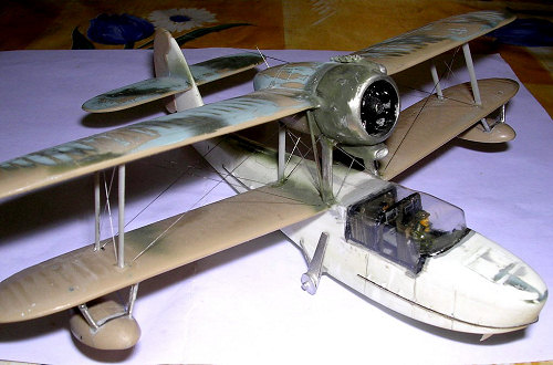
assembly starts with the fuselage and cockpit interior. This has a floor, detail
ribbing sidewalls, an instrument panel and three bulkheads, which by them would
have benefited if simple assembly diagram of the interior layout was provide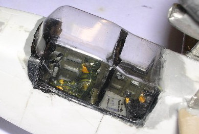 d.
This would also indicate that the crew seats were one behind the other then
side-by-side arrangement. This is besides other detail indicating where to fit
the observer’s chart table. Lack of this detail and adequate researching proved
to be time consuming. At this stage I painted the interior in cockpit green and
seat straps were also added. I also added crew figures from my spares box to
give a comparative indication of the scale of the aircraft. There is also other
detail such as the gaps behind the floor and sidewalls. This was found to be
intended to allow water which may enter the cabin to seep through and will then
be pumped by the on board bilge pump.
d.
This would also indicate that the crew seats were one behind the other then
side-by-side arrangement. This is besides other detail indicating where to fit
the observer’s chart table. Lack of this detail and adequate researching proved
to be time consuming. At this stage I painted the interior in cockpit green and
seat straps were also added. I also added crew figures from my spares box to
give a comparative indication of the scale of the aircraft. There is also other
detail such as the gaps behind the floor and sidewalls. This was found to be
intended to allow water which may enter the cabin to seep through and will then
be pumped by the on board bilge pump.
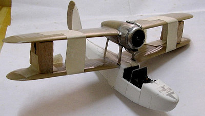 On
the positive side there is a well-detailed metal engine nacelle, which comes
with two separate metal intake scoops and a detailed metal exhaust manifold.
These along with the upper wing were completed as a sub assembly. The front
support struts for this assembly are also metal. All the other wing struts are
cut from measured lengths from plastic strip supplied. This also needed some fit
trials to cu
On
the positive side there is a well-detailed metal engine nacelle, which comes
with two separate metal intake scoops and a detailed metal exhaust manifold.
These along with the upper wing were completed as a sub assembly. The front
support struts for this assembly are also metal. All the other wing struts are
cut from measured lengths from plastic strip supplied. This also needed some fit
trials to cu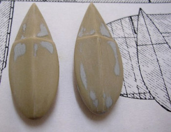 t
to correct length size. Reference to the front view on scale plans provided
indicated that the wing struts lean inwards as is on the actual aircraft.
t
to correct length size. Reference to the front view on scale plans provided
indicated that the wing struts lean inwards as is on the actual aircraft.
This is
the type of kit that one cannot rush as one goes assembling it and sufficient
time is allowed to allow the parts to set and dry completely before moving from
one stage to another. Finally the upper wing that is now a complete assembly
with the engine nacelle in place is lowered on the struts mounted on the lower
wings and center of the fuselage. At this stage one needs to ensure that the
correct angle of attack is obtained so that the propeller will clear the top
deck behind the cockpit canopy. After this is checked then the propeller could
be fitted at a later stage. The under wing floats are injection moulded in two
halves and has
 short
metal struts. One has to ensure to match the correct struts to the relevant wing
as these differ. The metal spatted tail wheel that has also the function of
water rudder and the side undercarriage legs are a final stage of assembly. For
a deck landing Sea Otter one needs to scratch build from metal wire of the
correct thickness the arrestor hook and some alteration at rear end of the
fuselage is also needed. At this stage I added the rigging using the predrilled
set of holes on the wings and fuselage parts etc. I have used nylon thread for
both the rigging and wireless arrangement.
short
metal struts. One has to ensure to match the correct struts to the relevant wing
as these differ. The metal spatted tail wheel that has also the function of
water rudder and the side undercarriage legs are a final stage of assembly. For
a deck landing Sea Otter one needs to scratch build from metal wire of the
correct thickness the arrestor hook and some alteration at rear end of the
fuselage is also needed. At this stage I added the rigging using the predrilled
set of holes on the wings and fuselage parts etc. I have used nylon thread for
both the rigging and wireless arrangement.
| COLORS & MARKINGS |
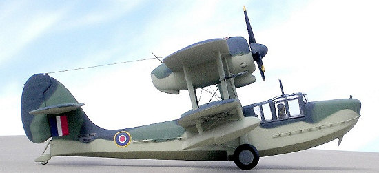
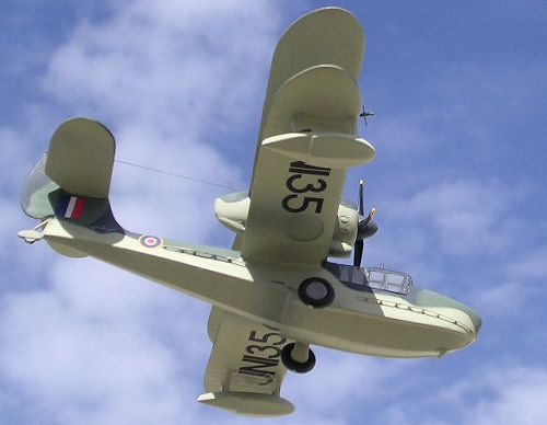 When the kit was complete
in one whole unit the canopy was masked and the lower surfaces airbrushed in
Sky. Lower areas were then masked and the upper surfaces had disruptive
camouflage of temperate scheme.
When the kit was complete
in one whole unit the canopy was masked and the lower surfaces airbrushed in
Sky. Lower areas were then masked and the upper surfaces had disruptive
camouflage of temperate scheme.
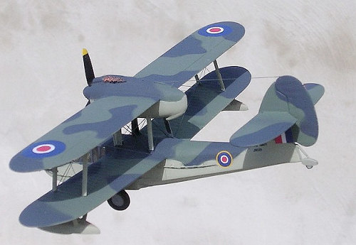
The decals that comes with the kit are of a very good quality and are for an aircraft serial JN135 when serving with 1702 Squadron Naval Air Station at Hal-Far, Malta circa 1949. The particular type also had small radar aerials attached at a horizontal angle to the outer wing struts. Fortunately I had photos of the real aircraft since not even these are indicated on the incomplete cover art work while there is some indication on the scale plans as to where these could be fitted in the event one makes his own as these are also absent among the kit parts. I built mine out of a strip of plastic with thin length of wires fitted horizontally on it and then attached to the front struts. A good reference source was the Aviation News Vol16 No2, which also depicts alternative finishes to choose from, and also Scale Aircraft Modelling Vol 16 No4. These sources were also helpful to locate the type of rigging and wireless arrangement suited for the type.
| CONCLUSIONS |
In spite of lack of adequate instructions that should have come with an otherwise quite accurate kit I have with some extra effort enjoyed making the Sea Otter that in the end makes a good replica of the real thing, This was also an opportunity to add another military type that frequented the airspace over Malta.
February 2007
Copyright ModelingMadness.com
If you would like your product reviewed fairly and fairly quickly, please contact the editor or see other details in the Note to Contributors.