Valom 1/72 Firebrand II
| KIT #: | ? |
| PRICE: | $ |
| DECALS: | options |
| REVIEWER: | Carmel J. Attard |
| NOTES: | Short run with etched parts. |
| HISTORY |
The
Blackburn Firebrand was a torpedo armed shipboard single seat fighter and its
origin goes back to the 1940 as a planned replacement to the Skua and the
Fulmar. This was in fact one of two designs considered by the admiralty
specification N11/40. The Firebrand made its maiden flight in February 1942 and
was powered by a huge Napier Sabre III, liquid cooled 24-cylinder engine that
drove a De Havilland three-bladed controllable pitch propeller. Being a large
carrier borne fighter the Firebrand was fitted with Fowler flaps, which
facilitated carrier deck take off and landings. Characteristic with the
Firebrand is that the tail fin is positioned well forward of the tail-planes and
it was also unique because of its wide undercarriage. The TF Mk II was an early
 version of the Firebrand with a speed of only 330-mph and was a very heavy
aircraft when compared with its predecessor shipboard fighters. The prototype
was not much favoured by the deck crew, as it was hard to service. This was
apart from other operational problems such as directional stability. With all
these unpopular characteristics the Firebrand was unsuitable as a fighter and
instead, development took the turn towards a torpedo fighter which was a gap
still to be filled by the RN, a time when the Swordfish and the Albacore were
yearning for a replacement.
version of the Firebrand with a speed of only 330-mph and was a very heavy
aircraft when compared with its predecessor shipboard fighters. The prototype
was not much favoured by the deck crew, as it was hard to service. This was
apart from other operational problems such as directional stability. With all
these unpopular characteristics the Firebrand was unsuitable as a fighter and
instead, development took the turn towards a torpedo fighter which was a gap
still to be filled by the RN, a time when the Swordfish and the Albacore were
yearning for a replacement.
Nine serial production aircraft were produced which were used for different tasks and trials. The Firebrand was designed to take the 457mm torpedo apart from its standard 20mm guns. The first flight in this form took place at Brough on the 31st of March 1943. Twelve TF Mk II aircraft were produced. However it was a time that supply of Napier Sabre III engines was hindered as these engines went in preference to power the Hawker Typhoons. Eventually specification N8/43 was issued in October 1943. This allowed the 2400HPBristol Centaurus VII, two row 18 cylinder sleeve valve radial engine to be adopted to the TF Mk airframe. This in turn meant that the design staff had to accommodate a wide frontal area of the Centaurus engine to a narrow fuselage of the Firebrand. Production followed with 27 Firebrands TFIII and further modification ended up with Firebrand TF Mk IV and 102 aircraft of the type were produced.
As a result of the lack of a suitable power plant at a critical stage in its development, the Firebrand remains a largely forgotten design in the annals of naval aviation history. It is possible that if it had the chance of combat active service it could have proved its success but it remains an important aircraft in naval military development
| THE KIT |
 The 1/72 scale model of the Blackburn
Firebrand TF MkII is a Valom kit made in the Czech Republic and hence rely on
resin parts, vac-form canopies, brass etch parts besides the injection moulded
main parts. The beautiful art work on the box lid depicts a Firebrand TF Mk II
loitering in a partly clouded sky and out over the open sea. This picture by
itself can serve as a good guide for one to select the correct colours to
decorate the model and also for the position of markings besides other detail.
The principal parts like the fuselage halves, tail plane, wing parts, cockpit
interior parts, undercarriage legs and tail wheel, canons, tail hook, etc, are
made of grey injection moulded plastic. Several of these components carry a fair
amount of engraved panel lines that makes the kit all the more attractive in
detail. Unusual about the propeller and spinner is that these come into a single
cast piece and at the same
The 1/72 scale model of the Blackburn
Firebrand TF MkII is a Valom kit made in the Czech Republic and hence rely on
resin parts, vac-form canopies, brass etch parts besides the injection moulded
main parts. The beautiful art work on the box lid depicts a Firebrand TF Mk II
loitering in a partly clouded sky and out over the open sea. This picture by
itself can serve as a good guide for one to select the correct colours to
decorate the model and also for the position of markings besides other detail.
The principal parts like the fuselage halves, tail plane, wing parts, cockpit
interior parts, undercarriage legs and tail wheel, canons, tail hook, etc, are
made of grey injection moulded plastic. Several of these components carry a fair
amount of engraved panel lines that makes the kit all the more attractive in
detail. Unusual about the propeller and spinner is that these come into a single
cast piece and at the same
 time
seems faithful to its actual appearance. The plastic is slightly on the thick
side yet there are no sink marks that can be a common defect with thick
sections. No flash was present and parts required little if any trimming in way
of the runner area.
time
seems faithful to its actual appearance. The plastic is slightly on the thick
side yet there are no sink marks that can be a common defect with thick
sections. No flash was present and parts required little if any trimming in way
of the runner area.
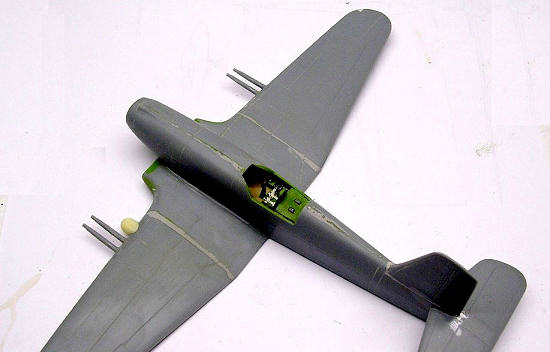
The cockpit is quite spacious and the interior is decorated with a control column having a round handle; a set of rudder pedals, small switches and knobs, complete instrument panel, safety seat belts all made out of etch brass. The two clear vac form canopies are of a suitable size so that much of the detail interior remains visible. However as there are two of such parts one may cut the cockpit so as to fit it in the open position and expose even further the interior. I also found that trimming the cockpit canopy to bring it to fitting size was a simple task by following the marked frame edge. Careful painting of the frame makes it look even more authentic. Three air intake grids are also supplied which have the intricate detail produced by brass etch metal.
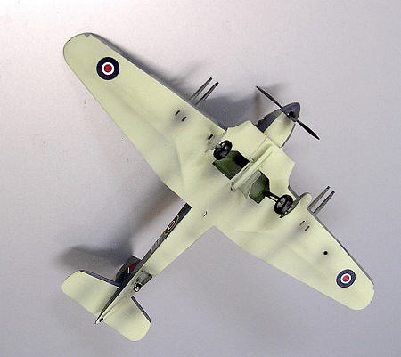
The leading edge random mounted on the port wing, the torpedo body and detailed main wheels are produced in cream coloured resin and the torpedo rear fins and two three bladed contra-rotating tiny propellers for the torpedo are produced in brass. Careful building of my model made me spot a number of points that will improve the final image and the overall accuracy of the model .
| CONSTRUCTION |
 a)
The contact area of the lower fuselage with the
front wing requires slight trimming to eliminate the existing gap and for
parts to make contact.
a)
The contact area of the lower fuselage with the
front wing requires slight trimming to eliminate the existing gap and for
parts to make contact.
b) Wing tip lights are cut in place and clear plastic is fitted and filed to shape.
c) Eliminate joint line fin on undercarriage legs.
d) Open up the upper nose mounted air intake.
e) A 3/16” hole requires to be drilled under the port wing to incorporate the landing light which is flush with the wing surface.
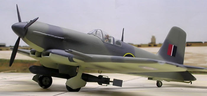
f) The inner undercarriage doors need to be tilted 20 degrees to the vertical when the torpedo is carried. The drawing front view that comes in the instruction shows these opening vertically.
g) The same wheel doors, parts mp8 and mp12, are shown in the instruction as fitted in the incorrect position. All the photos that I have seen shows that these should be fitted the other way round ie the square end should point forward and the sharp angled edge should point backwards.
h) The tail wheel should be fitted towards the rear in the tail wheel well and not at the recess provided which is moulded well forward inside the wheel well.
i) A taper fairing which conforms to the section of the exhaust manifold needs to be added ahead of the engine exhausts outlets. Reference to the nose area on the art work indicates this very clearly the shape it should be.
j)
A tiny whip aerial and a ‘U’ shaped antenna require
to be added under the fuselage at t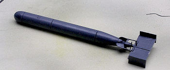 he
wing central section.
he
wing central section.
k) The two front air intake lips each require a piece of rounded thin plastic faired to shape. This will cover the front joint line of the kit parts and eliminate the vertical cut appearance which is non existent on the real aircraft.
l) The gun bore required to be drilled.
In the end I have preferred to place an accurate pilot figure in the spacious cockpit thus giving the scale and reveals what a sizeable shipboard fighter this should have been.
| COLORS & MARKINGS |
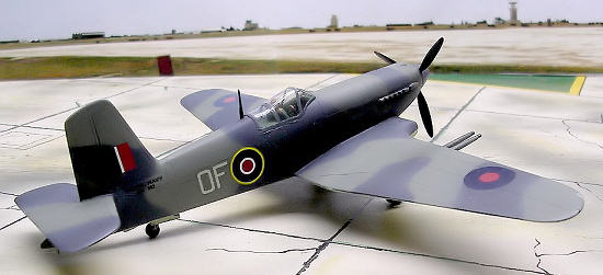
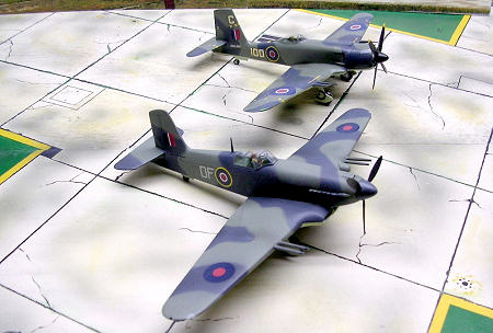 The instructions are quite good and easy
to follow with full colour information and position of markings for a 708
Squadron aircraft based at Lee-on-Solent, UK circa 1945. One should point out
that whereas the decal caters for a machine with serial number DK382, coded OF,
the instructions depicts DK383, coded OC and in the latter case the prop spinner
should be gloss red and not extra dark sea grey indicated.
The instructions are quite good and easy
to follow with full colour information and position of markings for a 708
Squadron aircraft based at Lee-on-Solent, UK circa 1945. One should point out
that whereas the decal caters for a machine with serial number DK382, coded OF,
the instructions depicts DK383, coded OC and in the latter case the prop spinner
should be gloss red and not extra dark sea grey indicated.
| CONCLUSIONS |
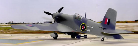
In the end the Firebrand turned into a pleasing model, giving the impression that it was a somewhat cumbersome torpedo fighter at its time of operational service. Having completed the Rareplanes TF5 radial engine version some time ago the TF MkII certainly made an interesting addition to my RN scale model section in my collection.
August 2006
Copyright ModelingMadess.com. All rights reserved. No reproduction in part or in whole without express permission.
If you would like your product reviewed fairly and fairly quickly, please contact the editor or see other details in the Note to Contributors.
Back to the Review Index Page 2015