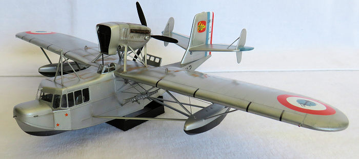
Special Hobby 1/48 Loire 130 CL
| KIT #: | |
| PRICE: | |
| DECALS: | Four options |
| REVIEWER: | Michael Rohde |
| NOTES: |
| HISTORY |
In 1933 the French Navy was in need of a new reconnaissance /light patrol bomber and issued requests to design and develop a prototype to six French companies. The company LOIRE won the contract and the first flight was carried out on November 19th 1934.
 The Loire
130 was produced from 1937 to 1942 and a total of 125 machines were built. These
aircraft were deployed on all catapult equipped warships of the French Navy
before the outbreak of WW 2 and were also stationed at shore bases in France ,
Africa and Indochina.
The Loire
130 was produced from 1937 to 1942 and a total of 125 machines were built. These
aircraft were deployed on all catapult equipped warships of the French Navy
before the outbreak of WW 2 and were also stationed at shore bases in France ,
Africa and Indochina.
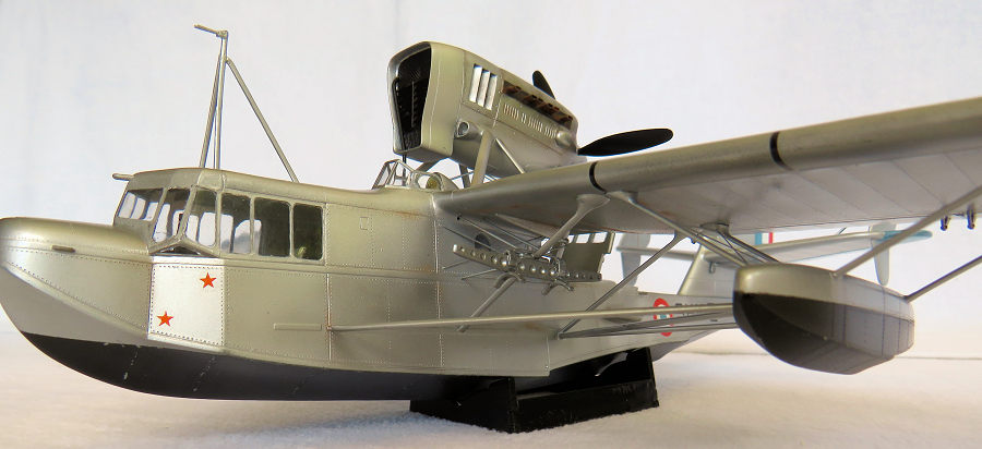
The Loire 130 saw active service in the defence of France in 1940 and after the armistice continued to be used by the Vichy Government. Some capture machines were evaluated by the German Luftwaffe
The Loire 130 CL ( Colonial) was modified to be used in tropical climates with a larger radiator and better protection from the elements for the crew members. This version was used in the French Indochina war against Siam and a few surviving examples were still flying at the end of WW 2, the last aircraft was seen in action in Saigon in 1949.
| THE KIT |
The kit contains 72 parts on 4 frames moulded in grey styrene, 11 clear parts, 2 clear vac form parts and 23 nicely rendered resin parts. Surface detail is crisp , panel lines are quite thin. No locating pins are present . The parts do show minimal flash and need extra care before processing . Overall fit of all parts is good.
Four decal options are available :
Loire 130 Cl serial No 71 Cat Lai Saigon French Indochina late 1940
Loire 130 CL serial no 6 Vatchai French Indochina 1944
Loire 130 CL serial no 15 Tripoli Italian Lybia 1941
Loire 130 Cl serial no 14 Fort de France Martinique Lesser Antilles 1942
The instructions are well laid out into a parts list incl paint chart ( Gunze colours). There are 18 construction stages necessary to complete the build.
| CONSTRUCTION |
I started with separating all the parts ( incl resin) from their respective frames ( or casting blocks and removed all flash and seams where necessary. The parts were organized into sections and stored in small containers accordingly. Stages 1 to 5 deal with the assembly of the cockpit interior ,bulkheads , raised cockpit floors ,radio equipment and forward cockpit side walls.
I did scratch build the raised fuselage interior
sidewalls according to original photos and added some more ribs and stringers as
well. The radio equipment ,instrument panel and wooden floors were painted
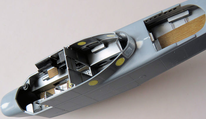 separately.
The rest received and overall coat of Tamiya chrome silver and then I moved on
to paint seat cushions , seat harnesses and details on the side walls
separately.
separately.
The rest received and overall coat of Tamiya chrome silver and then I moved on
to paint seat cushions , seat harnesses and details on the side walls
separately.
The radios and instrument panel were dry brushed with flat aluminium to highlight further details. Tamiya panel line accent brown and black was used to accentuate more of the raised interior detail .
Special Hobby does provide what they call ‘info view’ on page 5 giving a good overview of where the resin parts are located ( incl part numbers) Very helpful! Stage 5 deals with mating the fuselage halves together. The seams needed a bit of putty here and there but nothing major.
Step 6 and 7 deal with the tail plane assembly and another ‘info view’ drawing shows the correct alignment of the fins and dihedral .Again, there are no locator pins and one has to make sure of a close fit and making adjustments before glueing parts. I used a small amount of thin CA glue for sealing the remaining gaps.
Stage 8 deals with the assembly of the decking around the upper pilot’s position. I fitted the windscreen after attaching the wing, not as per plan.
Stage 9 – 11 brings us to assembling the engine pod and propeller. 10 of the parts involved are resin and only 3 are styrene parts.
The resin parts consist of :The radiator , air intakes , exhausts, propeller base, propeller blades and spinner. There is no shaft for the propeller hub and I decided to fashion one out of stretched sprue. ( had also the advantage that I had something to hold on to when I painted the propeller.)
 Stage 12 ;
The upper and rear fuselage decking and the main canopy are mated with the
fuselage. In this case careful dry fitting is of the essence the reduce any gaps
to a minimum. The main wing assembly is straight forward. It is recommended to
remove quite substantial injector pins on the insides Leading and trailing edges
need a bit of putty and sanding .Leading edge panel lines required re -scribing
afterwards.
Stage 12 ;
The upper and rear fuselage decking and the main canopy are mated with the
fuselage. In this case careful dry fitting is of the essence the reduce any gaps
to a minimum. The main wing assembly is straight forward. It is recommended to
remove quite substantial injector pins on the insides Leading and trailing edges
need a bit of putty and sanding .Leading edge panel lines required re -scribing
afterwards.
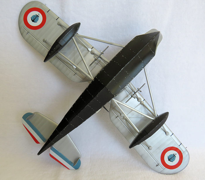
Stage 13: The finished main wing was dry fitted first and carefully adjusted before cementing. There are 8 aileron linkages to be fitted , 2 inner supporting struts and what seem to be fuel drain valves or nozzles for fog canisters. Two brazing wires on each side of the fuselage linking up with the inner struts have to be put in place now . Another helpful ‘info view’ drawing give us the correct position of these.
Stage 14.: This is the more difficult part of the build and deals with the main supporting struts, which also carry the bomb racks .Bracing struts for the racks have to be either made of stretched sprue , but in my case I used Evergreen rod to scale .Six of these have to be cut to size and installed. We have locator pins and holes to help us align the main struts, but I recommend to enlarge to holes a bit to assure a nice recess of the pins and minimise any gaps. I took extra time and care to test fit all of the struts before cementing.
Stage 15: The tricky part of the build continued: The Loire 130 had a rather intricate lattice work of outrigger float supports, which included V shaped bracing struts between floats and the fuselage. First I assembled the floats, cleaned up the seams and scribes additional panel lines and rivets. ( I forgot to mention earlier the I did this with the fuselage ,main wings and tail plane as well). The difficulty here is to align the floats correctly.
To prepare for this I repeated what I did with the main struts ( ie enlarged to locator holes to enable the locator pins to seat properly). I glued the 4 shorter struts onto the wings and let the glue set to the point where there was still some minute movement possible . Then I took the float and carefully rested it on the struts. Before commencing with this step, I improvised a jig for the model to rest on the bench. Satisfied with the alignment , I glued the floats into place and left things alone overnight. The V struts together with the single struts followed the day after. Again , Special Hobby supplied us with another ‘info view’ drawing for this particular sequence.
Period photos show that cross bracing wires were used on the inboard side of the floats. In this case I used 0.10 mm guitar string to do that. Special Hobby has not mentioned this detail in the instructions.
Stage 17 is about the engine support struts and respective cross bracing.( it is getting tricky ---again!). There are 2 V shaped main struts , 2 single struts and 2 V shaped cross braces to be installed. I repeated what I did with the wing struts. I enlarged the holes in the upper wing to ensure that the locator pins are nicely recessed. I glued the struts onto the engine pod first and let the glues set to the point where there was only minimal movement possible. To get the angle right I used a compass and measured the distance between the holes ( attachment points). I set the model into a jig beforehand, and had my hands free to wriggle the entire assembly into alignment before cementing.
 The engine
pod sits on an angle ( as shown on the ‘info view drawing). The alignment must
be correct to ensure that the propeller has enough clearance to the rear upper
fuselage decking. Before I mounted the engine pod , I painted the radiator and
the exhausts flat black and masked these items . The engine was aligned
carefully ( using the jig I made to support the model beforehand) and glued into
place. Another small detail is the pipe leading from the radiator down into the
upper fuselage. A piece of stretched sprue was cut to length and added later on.
The engine
pod sits on an angle ( as shown on the ‘info view drawing). The alignment must
be correct to ensure that the propeller has enough clearance to the rear upper
fuselage decking. Before I mounted the engine pod , I painted the radiator and
the exhausts flat black and masked these items . The engine was aligned
carefully ( using the jig I made to support the model beforehand) and glued into
place. Another small detail is the pipe leading from the radiator down into the
upper fuselage. A piece of stretched sprue was cut to length and added later on.
The windscreen ( pre painted) was added at this point and masked off. The pitot tube , mounted on a rather fragile tripod frame was left to after the model was painted. I drilled holes beforehand to make it easier to set this frame into its proper location later on. Now it was time to mask off the main canopy and the fuselage windows and get everything ready for air brushing the model.
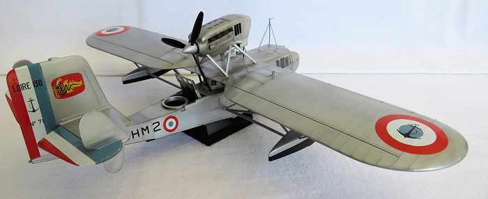
The colour scheme is fairly simple . The lower fuselage and float undersides are painted black. The fabric portions are held in Flat aluminium and the rest was painted with chrome silver. I pre shaded panel lines with flat black and used some AK polished aluminium to offset the silver chrome a bit. Weathering was held rather low key using pastels.
The decals went on like a dream. My choice was to depict a machine based at Cat Lai, Saigon French Indochina 1941.
| CONCLUSIONS |
Special Hobby has given us an example of one of the more obscure French aircraft serving during WW 2. It is a nice kit, well rendered, but not quite easy to build. Recommended for the more experienced modeller.
| REFERENCES |
25 October 2021
Copyright ModelingMadness.com. All rights reserved. No reproduction without express permission.
If you would like your product reviewed fairly and fairly quickly, please contact the editor or see other details in the Note to Contributors.