| KIT #: | 60325 |
| PRICE: | $11,000 yen at www.hlj.com |
| DECALS: | Three options |
| REVIEWER: | Tom Cleaver |
| NOTES: |
| HISTORY |
 After an
early crash allowed changes in the weapons system during the rebuild, the
requirement for carrying air-dropped bombs in the wings was dropped, while the
4-gun armament was changed to 6 weapons, three in each wing.
This meant the fuel tanks had
to be moved from the wing, while remaining on the center
of gravity. This resulted in the relocation of the cockpit aft to increase fuel
in the fuselage tank.
This severely restricted the pilot's view during the
all‑important maneuver of landing aboard a carrier, with the airplane gaining
the names “Old Hosenose” and “Ensign Eliminator”.
When that was coupled with overly‑stiff landing gear
that had a propensity to bounce when landed aboard by less than an expert pilot,
the Navy decided that as good as the airplane was, it was too much of a handful
for the average wartime‑trained Navy fighter pilot to safely and consistently
operate from the restricted deck of an aircraft carrier and substituted the
Grumman Hellcat for the Corsair aboard ship.
Interestingly enough, the British took the airplane
aboard carriers without the later fixes without difficulty, and VF-17 was able
to solve all the problems noted by the time they deployed to the Pacific in
September 1943.
One has to wonder just what was going on in the cool
intelligences at BuAer.
After an
early crash allowed changes in the weapons system during the rebuild, the
requirement for carrying air-dropped bombs in the wings was dropped, while the
4-gun armament was changed to 6 weapons, three in each wing.
This meant the fuel tanks had
to be moved from the wing, while remaining on the center
of gravity. This resulted in the relocation of the cockpit aft to increase fuel
in the fuselage tank.
This severely restricted the pilot's view during the
all‑important maneuver of landing aboard a carrier, with the airplane gaining
the names “Old Hosenose” and “Ensign Eliminator”.
When that was coupled with overly‑stiff landing gear
that had a propensity to bounce when landed aboard by less than an expert pilot,
the Navy decided that as good as the airplane was, it was too much of a handful
for the average wartime‑trained Navy fighter pilot to safely and consistently
operate from the restricted deck of an aircraft carrier and substituted the
Grumman Hellcat for the Corsair aboard ship.
Interestingly enough, the British took the airplane
aboard carriers without the later fixes without difficulty, and VF-17 was able
to solve all the problems noted by the time they deployed to the Pacific in
September 1943.
One has to wonder just what was going on in the cool
intelligences at BuAer.
(As a note, a recent book by Dana Bell on the F4U-1 states that his research into primary sources found that the Corsair was not initially put on carriers to simplify the parts situation. The Navy felt the Corsair was totally carrier capable as it was and did not require any advanced skills. Bell states that the stories regarding too much 'bounce' on landing are a myth that has been perpetrated over the years. Ed)
“Butch” Davenport and
VF-17:
Born in Sterling
Michigan on March 14, 1918, Merl W.
“Butch” Davenport left Wayne University in his junior
year to join the Navy AvCad program, and received his Wings of Gold in May 1942.
Shortly thereafter he was assigned to VF-17, which was
at the time set to be the first carrier squadron to operate the new F4U-1
Corsair.
Soon promoted to Lt.(j.g.)
when his engineering prowess made itself known, Davenport was assigned by
squadron leader Tom Blackburn as the engineering officer.
He worked closely with the Vought tech reps as the
squadron fought to deck-tame the Corsair and was instrumental in developing the
spoiler placed on the right wing to give advance warning of stall and thus
prevent the deadly snap roll the airplane was
 capable of
during a stall in landing configuration; he was also influential in coming up
with the fix to “de-bounce” the Corsair by reducing the pressure in the main
gear oleos, as well as the removal of the top three cowl laps to prevent oil
smearing the canopy.
capable of
during a stall in landing configuration; he was also influential in coming up
with the fix to “de-bounce” the Corsair by reducing the pressure in the main
gear oleos, as well as the removal of the top three cowl laps to prevent oil
smearing the canopy.
Once VF-17 entered
combat in the Solomons, Davenport took awhile to get his shooting eye.
In January 1943, following the squadron’s return for
their second tour in Bougainville, he shot down two Zeros.
In February he was credited with four on February 16,
the last “big day” over Rabaul, and a shared-credit a week later just before the
IJNAF evacuated their surviving aircraft back to Truk.
While not one of the highest scoring aces in the
squadron, Davenport’s efforts as engineering officer were of incalculable
importance for VF-17's success in combat, and for the eventual deployment of the
Corsair aboard Navy fleet carriers.
| THE KIT |
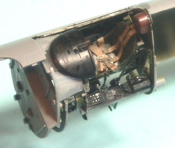
The kit features a
detailed R-2800 engine that can be displayed with the cowling open, the option
of having the wings spread or folded and the flaps raised or dropped, and the
landing gear extended or retracted. The engine is nothing to write home about.
It’s very definitely not “super-detailed,” and lacks
most of the detail one finds in the R-2800s Trumpeter released in their
Corsairs, Thunderbolts, Hellcats and Bearcats.
Perhaps most importantly, it’s still not the right
engine for an F4U-1A, but rather for an F4U-1D.
This is most notable in the shape of the magnetos.
Interestingly, Trumpeter provides the
 different
magnetos as part of their R-2800 package.
If one is going to display the model with the engine
open, and possesses the now “obsolete” Trumpeter F4U-1A kit, it might be
advisable to consider robbing the Trumpeter engine from that kit and using it on
this kit.
different
magnetos as part of their R-2800 package.
If one is going to display the model with the engine
open, and possesses the now “obsolete” Trumpeter F4U-1A kit, it might be
advisable to consider robbing the Trumpeter engine from that kit and using it on
this kit.
For those for whom “too
much” is not enough, here is a list of things the Serious Corsair Modeler will
still want to consider doing for the kit, from a list posted at The Most
Exceptionally Serious Hobby Page In The World:
Rivets: The kit wing and fuselage are covered with
tiny indentions meant to replicate rivets. The Vought drawings call out the use
of surfacer for the wing outer panels front "D" section and the entire center
section for smooth surfaces. The fuselage has many spot welded assemblies. Same
for fuselage, vertical and horizontal stabilizers.
Cockpit:
Missing the landing gear emergency extension CO2 bottle.
Left side next to seat. The kit provides the fuel tank vapor CO2 dilution
bottle.
Missing flap control upper left in front of part D21.
Not all F4U‑1 had the padded head rest parts B21 & B22.
Pilots seat installation has early frame seat- seat
assembly was changed to later "raised cabin" type at BuNo. 17492, 17494 and
subsequent according to parts list.
Missing chart board installation under instrument panel.
Add auxiliary gunsight on instrument cowling left of
illuminated gunsight. Check battery and cockpit heater installation. Check seat
and shoulder belt installation. Check radio receiver switch panel installation
on right side. Bomb control missing, left side next to seat.
Many cockpit placards to add.
Consider adding oxygen hose and mask. Consider adding
raft pack, parachute, seat cushion and straps to seat bottom.
Add details to inside of sliding canopy section.
According to Dana Bell’s recent research, the flare
pistol should now be used.
Fuselage:
The tail wheel doors had ribs instead of stamped sheet
stiffeners. Missing chain operator and linkage for tail wheel doors. Kit
provides some, parts F9 through F11.
Check tail wheel assembly. There were at least three
different types of tail wheels used and different yokes.
Dashpot for arresting hook
 and spring
assisted tail wheel strut missing.
and spring
assisted tail wheel strut missing.
Engine and cowling:
Kit provides top three cowl flaps battened down or
replaced top three with a sheet metal pan. If cowl flaps open, add detail to
inside of cowl flaps depending on whether individually hydraulically operated (all‑around
cowl flaps) or modified for cable operation. Like Vector (?) 1/48 resin set.
Detail inside of nose cowl, part G8, crude. Consider replacing with ribs.
Barracuda resin for engine details.
Kit provides engine upper baffles, parts K13 and K16.
Missing the other baffles for the cylinders. All kits with R‑2800 miss this. Add
inter‑cylinder oil lines for lower cylinders. See R‑2800 manual for other lines
visible from front. Add spark plug wiring.
I’m sure if you do all
that you’ll have a stunner of a model.
For me, as I read the list, I kept thinking of “John
Clark’s rule” (Those who have read a Tom Clancy novel will remember this): “Good
enough is good enough, and perfect is a PITA.”
For me, the kit is “good enough.” Your mileage may vary.
A lot of complaints have been made about the kit’s use of rubber wheels, since it’s a “well-known fact” that rubber tires are death to a model. For once and for all: the truth is that there was only ever one airplane kit that had problems with rubber tires: the F7F series released 20 years ago by AMT. There was some sort of chemical reaction between the rubber tires and the plastic hubs, that resulted in them melting. This has not been a problem with kits since. I have Trumpeter kits that are now over ten years old with rubber tires and there has been no problem with any of them. I have used the rubber tires on all the Tamiya Spitfire releases and their Mustang. I used them on the F4U-1. No problem. I am sure, however, that facts will never get in the way of “common knowledge” in the scale modeling hobby, at least in certain places. Were it not for “uninformed comment,” 95 percent of modelers who post on internet forums would be mute.
| CONSTRUCTION |
The one Big Secret to a
successful project with this kit is READ AND FOLLOW THE FREAKING INSTRUCTIONS!!!
I realize this is a radical, perhaps subversive act for
many modelers to undertake, but just like with the Wingnut Wings kits with their
solid instructions, following the way Tamiya has laid this kit out will resolve
all your problems.
 Another item:
while many modelers I know who are working on the kit have reported no problems
with the engine, the instructions there as regards getting everything aligned
properly in construction are just vague enough that it is very definitely not
that hard to end up attaching the front and rear cylinder banks “one cylinder
over”, resulting in having to pull it apart and start over (ask me how I know).
There is a simple solution to this that will insure
everything is assembled correctly here, and that is to assemble everything from
back to front: attach the exhausts to the firewall, attach the circular exhaust
section to the firewall, then attach the rear engine bank.
Attach the exhaust pipes between banks, then attach the
front bank.
Then attach the front of the engine with the magnetos, and all
will be exactly aligned.
Another item:
while many modelers I know who are working on the kit have reported no problems
with the engine, the instructions there as regards getting everything aligned
properly in construction are just vague enough that it is very definitely not
that hard to end up attaching the front and rear cylinder banks “one cylinder
over”, resulting in having to pull it apart and start over (ask me how I know).
There is a simple solution to this that will insure
everything is assembled correctly here, and that is to assemble everything from
back to front: attach the exhausts to the firewall, attach the circular exhaust
section to the firewall, then attach the rear engine bank.
Attach the exhaust pipes between banks, then attach the
front bank.
Then attach the front of the engine with the magnetos, and all
will be exactly aligned.
Another point about the engine: since it’s not that
much of a super-detailed whoopy-do, plan to close the cowling (particularly
since those parts stay in position about as well as the cowlings on the
Spitfires and Mustangs do) and just concentrate on the front of the engine, you
can’t see anything else anyway.
And now on to building the model.
This kit requires that
you carefully clean up each part and remove all bits of sprue attachment, since
the fit of this kit is overall tight and precise.
If you don’t do this, you’ll have fit problems
throughout the model.
Make certain all sub-assemblies are tightly attached in
the proper position.
“Close enough” doesn’t work for this kit.
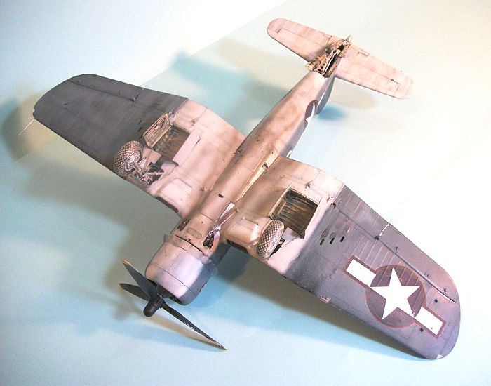
Unlike the F4U-1, the
F4U-1A uses Interior Green throughout for the cockpit and fuselage interiors.
If you are modeling a VF-17 airplane, these were early
F4U-1As which had the wheel wells and interiors of the gear doors painted
Interior Green also.
Later F4U-1As had the wheel well and gear doors painted
in the lower surface white color.
Check your references for the airplane you are doing.
VF-17 Corsairs also had the landing gear painted
aluminum lacquer.
 hen
assembling the cockpit interior, it is important to look at the assembly
sequence, because there are a parts that fit over other parts and they must be
attached in the correct sequence or things will not come together.
hen
assembling the cockpit interior, it is important to look at the assembly
sequence, because there are a parts that fit over other parts and they must be
attached in the correct sequence or things will not come together.
With regard to the wing
assembly, be absolutely certain to get the upper surface tightly attached to the
outer bulkhead of the landing gear well.
This is particularly important if you are doing the
wings-spread option, since if that is not nice and tight you will not get smooth
mating to the outer wing.
Also, for the
wings-spread option, do not put any of the parts shown attached inside the
folding area.
You can’t see them and they will get in the way of a good tight
fit.
While this spar assembly is far stronger than that of the 1/48 kit, it
is still a good idea to put some Evergreen strip inside the wing, particularly
the area aft of the spar to the flaps.
This will provide extra “grabbing area” for the glue and
insure a solid fit.
I was glad to see that,
for once, the flaps-down option wasn’t the only one that worked (as is the case
with the 1/48 kits).
In the Corsair, it’s in the Pilot’s Notes to raise the
flaps immediately on touchdown because they are liable to foreign object damage
on the airstrip, and they blank the prop blast that is important in steering on
the ground.
I originally liked the flaps-down option back when Tamiya first
came out with it, but after looking at the many, many photos of Corsairs with
the flaps up and the few with flaps down, I went with technical accuracy and
raised the flaps.
The only place I found
any fit problem was along the centerline seam of the lower rear fuselage.
There was a big seam gap there that took both plastic
putty and cyanoacrylate glue to make it disappear.
I didn’t have to use any filler anywhere else on the
model.
Once the model was assembled, it presented a very
solid structure.
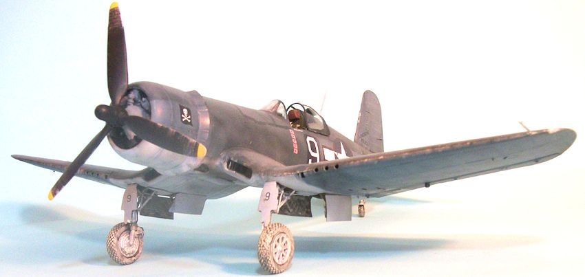
VF-17 soon replaced
their original props with Hellcat props that were a bit shorter and less subject
to wear from the coral strips they were flying from.
I used a prop from a Hasegawa Hellcat for this model.
| COLORS & MARKINGS |
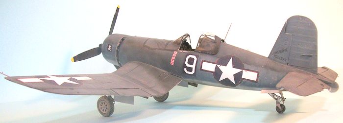
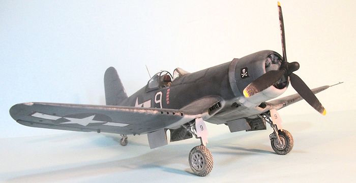
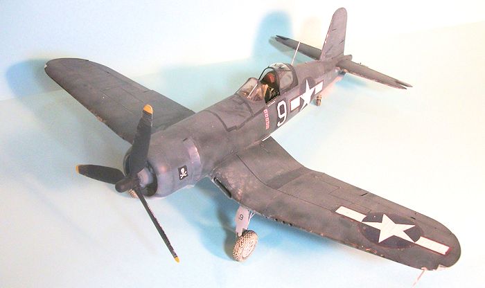
I had an old Aeromaster
sheet that had Davenport’s “Lonesome Polecat” with the “9" on a dark blue
background.
Researching the airplane with my Christmas Present, Lee Cook’s
“The Skull and Crossbones Squadron: VF-17 in World War II,” I was finally able
to figure out that Davenport had three Corsairs during his time in VF-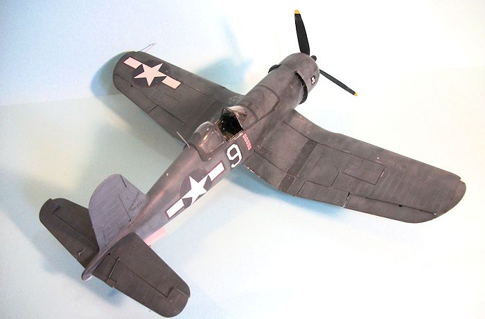 17,
all named “Lonesome Polecat” using the same stencil, with no indication of a
later airplane in the name.
The first was “33" in which he was scoreless.
The second was a replacement F4U-1A, with “9" painted
directly on the camouflage; he scored two victories in this airplane before
Country Landreth managed to overturn it in a landing accident in late January.
The third “Lonesome Polecat” was an earlier squadron
airplane, a fact that is identifiable on one photograph by the fact you can see
the original red surround of the national insignia under the blue repaint.
This airplane also had a different earlier number, which
was covered with fresh Sea Blue and then two different “9" numerals were painted
over on either side.
This is the airplane with the eventual six victory
flags.
It is also interesting to note that this airplane had the white medical
tape used to seal the gas tank overpainted with Sea Blue at a later time, since
it is darker than the original surface.
17,
all named “Lonesome Polecat” using the same stencil, with no indication of a
later airplane in the name.
The first was “33" in which he was scoreless.
The second was a replacement F4U-1A, with “9" painted
directly on the camouflage; he scored two victories in this airplane before
Country Landreth managed to overturn it in a landing accident in late January.
The third “Lonesome Polecat” was an earlier squadron
airplane, a fact that is identifiable on one photograph by the fact you can see
the original red surround of the national insignia under the blue repaint.
This airplane also had a different earlier number, which
was covered with fresh Sea Blue and then two different “9" numerals were painted
over on either side.
This is the airplane with the eventual six victory
flags.
It is also interesting to note that this airplane had the white medical
tape used to seal the gas tank overpainted with Sea Blue at a later time, since
it is darker than the original surface.
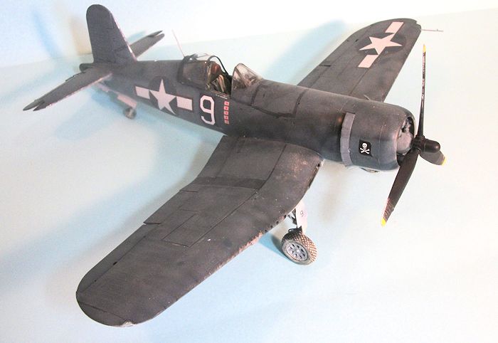
I used the Aeromaster
decals for Davenport’s personal markings, and the red-surround national
insignias from the kit, which I then overpainted with Sea Blue, leaving
“holidays” through which you can see the original red color.
I brush painted Sea Blue over the area where the tape
would have been.
I applied extensive
exhaust stains on the lower fuselage, using Tamiya NATO Black, Dark Grey and
Hull Red.
The oil stains aft of the cowling on the fuselage and upper wing
were done with thinned Tamiya Semi-Gloss Black, as were the stains aft of the
guns.
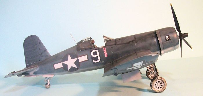
Photos also show that
many of these Corsairs didn’t have heavy “dings” so I only lightly “dinged” it
with Tamiya flat Aluminum.
I used Tamiya “Mud” to “muddy up” the landing gear and
wheel wells.
| CONCLUSIONS |
When making a Solomons‑based Corsair, I think the
following is important information on which to base one’s painting and finishing
decisions, particularly for Marine Corsairs:
 As far as
individual airplanes belonging to a specific pilot was concerned, while a man
might be assigned an airplane, and while his fighting score might be maintained
on that airplane by its crew, the reality was that pilots flew whatever airplane
was "in service" at the time the mission was scheduled to take off.
(VF-17, being a Navy squadron, was the only one there
where pilots had their own airplanes and mostly flew them.) Maintenance in the
field on the island airfields was limited to what was necessary to allow the
airplane to fly and fight.
As far as
individual airplanes belonging to a specific pilot was concerned, while a man
might be assigned an airplane, and while his fighting score might be maintained
on that airplane by its crew, the reality was that pilots flew whatever airplane
was "in service" at the time the mission was scheduled to take off.
(VF-17, being a Navy squadron, was the only one there
where pilots had their own airplanes and mostly flew them.) Maintenance in the
field on the island airfields was limited to what was necessary to allow the
airplane to fly and fight.
Paint faded rapidly
under the hot tropic sun, while the "sandblast effect" of operating from a
crushed‑coral or dirt runway did nothing to improve the appearance of the
fighters, not to mention the "dings" that happened as crewmen climbed over the
airplane to service it; exhaust stains and gunfire stains were not washed off at
the conclusion of a mission, while the fact that the gas tank leaked meant that
the airplane's painted surface became even more corroded from the effects of
high‑octane gasoline on it.
The result, as can be seen by even the quickest perusal
of contemporary photos of Corsairs in the Solomons is that creating an accurate
representation of one of these airplanes is one of the few times when
"weathering" a model that "too much is not enough" is the rule to follow, rather
than the more usual "less is more."
January 2015
Review kit courtesy of HobbyLink Japan. Order yours at this link.
If you would like your product reviewed fairly and fairly quickly, please contact the editor or see other details in the Note to Contributors.