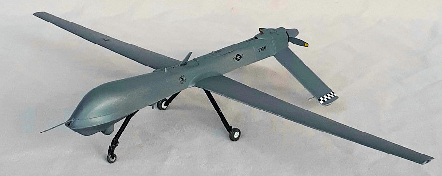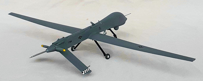
Bronco 1/48 RQ-1 Predator
| KIT #: | FB 4000 |
| PRICE: | $28.00 |
| DECALS: | Three options |
| REVIEWER: | John Summerford |
| NOTES: | Choice of building either a RQ-1 or MQ-1 |

| HISTORY |
Courtesy of the National Museum of the Air Force
Technically, the RQ-1 Predator is not just an aircraft but an entire system. Developed as an Advanced Concept Technology Demonstration (ACTD), this system consisted of four unmanned aerial vehicles (UAVs), a ground control station, a satellite communications terminal and 55 personnel. The Predator UAV in the museum -- the most recognizable part of the system -- provided military commanders with an Intelligence, Surveillance and Reconnaissance (ISR) platform capable of flying over dangerous areas for extended periods without risk to a human pilot.
 In January
1994 the Department of Defense awarded a contract for ten Predator aircraft to
General Atomics Aeronautical Systems of San Diego, Calif., and the first
Predator flew just six months later in July 1994. Within a year, Predators
deployed to Europe, where they proved their value in operations over Bosnia from
July 1995 to March 1996. In April 1996, the Secretary of Defense selected the
U.S. Air Force as the operating service for the RQ-1 Predator system, and the
system entered production in August 1997. In subsequent deployments, the
Predator continued to demonstrate its value to military leaders.
The pre-production version Predator aircraft was designated RQ-1K, but the entire system with all the components was designated the RQ-1A. Powered by a four-cylinder, 81-hp Rotax 912 engine, the RQ-1K aircraft could cruise at 87 miles per hour for 16 hours. The production version Predator aircraft was designated the RQ 1L, and it was equipped with a turbo-charged Rotax 914 engine producing 105 horsepower. The UAV on display is an RQ-1K.
In flight, the UAV and its on-board sensors are controlled by the ground crew with a direct data link. However, when the aircraft is flown beyond the range of a direct link, the ground crew maintains control though a satellite data link. The equipment carried in the bottom turret can provide live video, still photographs, or radar imagery in all weather conditions, day, or night. Using satellite data links, the information gathered by a Predator can be shared instantaneously with commanders around the world.
Designed and built to be easily deployed worldwide, the Predator systems operated from Creech Air Force Base, Nev. In February 2001 the Predator demonstrated a new potential. In a test program, it successfully fired a laser-guided Lockheed Martin AGM-114 Hellfire anti-tank missile at a stationary target.
| THE KIT |
 2009 is the
year in the copyright notice. The kit is out of production, but it can be
sourced from on-line vendors.
Two sprues of neutral gray styrene hold 51 pieces and a clear sprue holds five. The fuselage is molded as top and bottom pieces, with two different bottoms. The difference being that the MQ-1 has a pylon between the landing gear and the RQ-1 does not. The instructions are not clear on this point and one must look at the paint and decal illustrations to spot the difference. There is no photo-etch and decals are supplied for USAF and Italian subjects.
Instructions are printed on both sides of a sheet folded in half and a supplemental paint and decal sheet. The first page includes a description, parts map icon explanation, and paint chart with Gunze Sangyo, Hobby Color, Humbrol, and Tamiya brands. The next two pages are the assembly instructions and the last page part of the paint and decal schemes.
| CONSTRUCTION |
 Even though
there is not a cockpit, there are internal fuselage pieces to add to the lower
piece of your choice. Starting with the sensor pod, the lenses were tinted blue,
then masked with latex and the pod assembled and installed.
Slots for the pylons in the wings were filled and the wing glued into place. The prop is supposed to be mounted to a shaft in the spinner. Unfortunately, there was not a shaft in this example, so one was added to complete the subassembly. The instructions call for ballast to be placed in the nose, but not how much. The top piece traps the interior parts. After gluing the fuselage together, the correct engine access panel for the RQ-1was glued in place.
In addition to adding the underside bits in Step 2, the instructions also call for adding the landing gear. The gear was left off for installation after painting. Once the upper bits were installed, it was time for paint.
| COLORS & MARKINGS |
 Nuttin’
complicated ‘bout paint’n this one. It’s gray. After applying a rattle can of
automotive primer, then acrylic paint, a gloss coat prepared the model for the
decals.
The decaling diagram is suspect. The stars and bars are shown on opposite wings from the usual locations and the stars point aft. For this model, two different squadron badges are called for, one on each side. The checkerboards for the tails wrap around the leading edges. They would be easier to apply by cutting them into upper and lower segments. The decals behaved well. When they were dry, a satin coat sealed them.
Aligning the landing gear with the wings and tail was a challenge. The main legs were bent after the glue cured to get everything squared. The final piece was the nose antenna, which was a length of .020 music wire.
| CONCLUSIONS |
This is a simple kit and the parts fit very well together making this an easy build, though the nose wheel is a bit fiddly. Perhaps the most difficult aspect is interpreting the instructions. If one wishes the make a contest winner, a bombed-up MQ-1 would find more favor due to the additional effort.
25 November 2024
Copyright ModelingMadness.com. All rights
reserved. No reproduction in part or in whole without express permission from
the editor.
Review kit courtesy of my wallet If you would like your product reviewed fairly and fairly quickly, please contact the editor
or see other details in the
Note to
Contributors. Back to the Main Page
Back to the Review
Index Page
Back to the Previews Index Page