Wire Rigging Biplane Models
by Brian Baker
Background
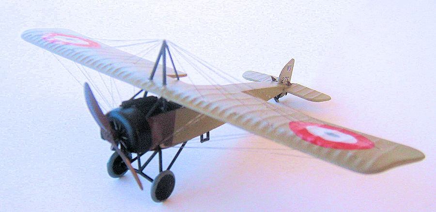
I have seen many models of biplanes over the years,
many of which did not have the wire bracing normally associated with biplanes
and even early monoplanes. The first airplanes were, of course, made entirely of
wood, and they were braced with various kinds of wires and struts. Later, into
the nineteen thirties, when all-metal airplanes appeared, many were still wire
and strut braced, but later, approaching the forties,
 cantilever structures
became more common, and the wires and struts disappeared. However, to those of
us who model older airplanes, the wires are certainly a part of any airplane we
model, and these should be included in the models to make them look more
realistic.
cantilever structures
became more common, and the wires and struts disappeared. However, to those of
us who model older airplanes, the wires are certainly a part of any airplane we
model, and these should be included in the models to make them look more
realistic.
I began building models when I was about 6 years old, and by the time I was in high school, in the early fifties, I was building wooden models from scratch, using whatever wire I could find to represent the rigging. Into the sixties, when I became involved in the first Phoenix, Arizona, IPMS chapter, I was building models from commercially available plastic kits all in 1/72 scale. We had a very nice IPMS chapter, with a number of serious modelers. One of our members, Ray Sweet, an employee of Goodyear Aviation in Goodyear, AZ, worked out a system of biplane rigging, and he taught me the process. Ray picked up lots of scrap electronic wire from the waste bins at Goodyear, material that would have been thrown away, and he had a large store of it at home. When I showed interest in the process, he showed me how to do it, and gave me a whole pile of the wire scraps, which I still use today, over 60 years later. This is the process.
Research
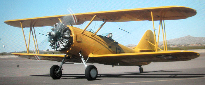
The first step in the process is finding out where the wires are located on the airplane. There are four major types of wire structures, strut bracing wires, flying and landing wires, which brace the wings in flight and while sitting on the ground, control cables, which actuate the rudder, elevators, and ailerons, and radio antenna wires, which were common on aircraft using low frequency radios. More modern aircraft today use VHF radios, which only require a short whip antenna. But a few old aircraft still carry the LF antennas, mainly for historical purposes.
 This means that you will have to have accurate three
view drawings or photos that show the wire installations. If you are modeling an
actual aircraft, and have access to one at an airport or museum, take a series
of detail photos showing the locations of all of the wires. If not, find a
reference book that has numerous photos of the airplane in question. There are
many aviation history books available today, and most have useful photos. In
addition, sometimes the kit instructions include wire locations in their
instructions, and even the kit box art could have useful information. You will
need some kind of reference to locate the wire accurately.
This means that you will have to have accurate three
view drawings or photos that show the wire installations. If you are modeling an
actual aircraft, and have access to one at an airport or museum, take a series
of detail photos showing the locations of all of the wires. If not, find a
reference book that has numerous photos of the airplane in question. There are
many aviation history books available today, and most have useful photos. In
addition, sometimes the kit instructions include wire locations in their
instructions, and even the kit box art could have useful information. You will
need some kind of reference to locate the wire accurately.
The actual wires on most airplanes from the twenties on were flat, airfoil shaped wires with the ends equipped with threaded fittings to attach them to the structure. The airfoil shape was to reduce the aerodynamic drag created by the wires, increasing the maximum speed slightly. A photo of one of these wires is attached, showing the shape of the wire and fitting. My father, who learned to fly in the twenties in a Curtiss JN-4D Jenny training biplane he bought as Army surplus, took a scrap wire from an airplane in that time period and cut it short, grinding it to a sharpened end and chromed, making a very attractive letter opener. I still have it as a family heirloom today.
It is nearly impossible to duplicate the wire on a model in very small scales, but a round wire works just as well.
The wire
Ray Sweet gave me a batch of scrap electronic wire,
which consists of short lengths of less than 12 inches, encased in rubber or
plastic insulation. There are larger wires available in hardware stores, which I
have used for bracing wires on larger airplanes, but I primarily use the
electronic wire for smaller 1/72 scale models. I usually cut the wires with a
knife or wire cutters to a length of about four to six inches, and then strip
off the insulation, rolling the wire against a knife to separate the insulation.
It pulls off easily, leaving
 about 12 very fine pieces of wire in a usually
wobbly shape. The wire should then be separated or pulled apart into individual
pieces. Now the problem is getting it straight. This is really not a problem if
you have a completely flat hard surface to work on, preferably formica. I use a
small hand roller (photo enclosed) made of a flat sheet of aluminum with a
handle superglued to one side. Ray gave this to me, and I still use it 60 years
later. Rolling this contraption over an individual wire will eventually cause it
to straighten out. I then put it in a flat container, although I sometimes have
to re-roll it before I attach it to a model. When I cut the end off to get the
proper length, I keep the scraps, as they are useful for short bracing wires,
such as landing gear bracing or control cables. They should always be handled
with a set of pointed tip tweezers. Otherwise, they will nearly always bend.
about 12 very fine pieces of wire in a usually
wobbly shape. The wire should then be separated or pulled apart into individual
pieces. Now the problem is getting it straight. This is really not a problem if
you have a completely flat hard surface to work on, preferably formica. I use a
small hand roller (photo enclosed) made of a flat sheet of aluminum with a
handle superglued to one side. Ray gave this to me, and I still use it 60 years
later. Rolling this contraption over an individual wire will eventually cause it
to straighten out. I then put it in a flat container, although I sometimes have
to re-roll it before I attach it to a model. When I cut the end off to get the
proper length, I keep the scraps, as they are useful for short bracing wires,
such as landing gear bracing or control cables. They should always be handled
with a set of pointed tip tweezers. Otherwise, they will nearly always bend.
The wire can be trimmed while lying flat on the desktop by cutting it with an Exacto knife. A round tipped blade works better for me, but a straight tip also works. The next problem is measuring and attaching the wire to its proper position on the model.
Installation
 I have a number of tools on my workbench that I use
for wire installation. Most important is a measuring device, and I use a set ot
pointed tipped dividers to measure the length required. If this doesn’t work
because of the shape of the model structure, I just use a piece of flat index
card or heavy paper, cut to a small size, to cut a piece to size so I can insert
it into the gap the wire is going to fill. When I have the length measured, I
cut the wire to size and using a set of sharp pointed tweezers, I test fit it to
the model. When I am satisfied that the wire is the correct length, I use a
pointed dental tool to attach a tap of white glue to the higher surface of the
wire location. I then attach one end of the wire to that glue spot, and
carefully move the other end to the opposite end location. You have to be very
careful moving the wires around, as they will bend very easily, and if they do,
you have to remove the wire and restraighten the wire using the roller bar.
I have a number of tools on my workbench that I use
for wire installation. Most important is a measuring device, and I use a set ot
pointed tipped dividers to measure the length required. If this doesn’t work
because of the shape of the model structure, I just use a piece of flat index
card or heavy paper, cut to a small size, to cut a piece to size so I can insert
it into the gap the wire is going to fill. When I have the length measured, I
cut the wire to size and using a set of sharp pointed tweezers, I test fit it to
the model. When I am satisfied that the wire is the correct length, I use a
pointed dental tool to attach a tap of white glue to the higher surface of the
wire location. I then attach one end of the wire to that glue spot, and
carefully move the other end to the opposite end location. You have to be very
careful moving the wires around, as they will bend very easily, and if they do,
you have to remove the wire and restraighten the wire using the roller bar.
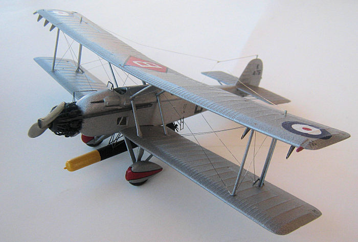
Care in Handling
 One thing to realize is that these wires are VERY
fragile, and bend easily. Therefore, it is best to work in a sequence that
reduces the risk of wire bending. I do this by attaching the smaller inside
wires first, such as strut and landing gear bracing wires. Then I attach control
cables. After that, I install the landing and flying wires between the wings.
Landing wires attach from the upper inside struts and run to the lower outside
wing struts to brace the wings while the airplane is on the ground. The flying
wires run from the lower fuselage to out upper wingtip struts, and brace the
wings while the airplane is flying.
One thing to realize is that these wires are VERY
fragile, and bend easily. Therefore, it is best to work in a sequence that
reduces the risk of wire bending. I do this by attaching the smaller inside
wires first, such as strut and landing gear bracing wires. Then I attach control
cables. After that, I install the landing and flying wires between the wings.
Landing wires attach from the upper inside struts and run to the lower outside
wing struts to brace the wings while the airplane is on the ground. The flying
wires run from the lower fuselage to out upper wingtip struts, and brace the
wings while the airplane is flying.
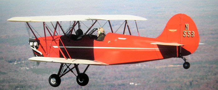
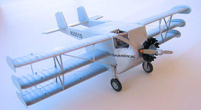
Conclusions
One thing to remember is that every airplane’s wiring is different, and even planes of the same make and model can have different wiring patterns. Just be sure to use a photo or drawing of the particular plane you are modeling to ensure accuracy. If you build a lot of models, a large library of aviation books or photos is essential. Or, sometimes, you can find photos or particular airplanes on line. Whatever you do, remember that the research is important, and that once the wiring is completed, the model must be treated with the greatest of care. If you are moving the model, pack it carefully so it cannot move or be in contact with another model. I would not advise sending it anywhere in the mail unless you don’t mind doing the almost unavoidable repair work. Remember, if it ain’t broke, you won’t need to fix it.
I hope that this article helps some of you to build more detailed models. Just remember that Ray Sweet, late of IPMS Phoenix, developed this process. He would be the one to thank, but he has long passed. Thanks, Ray.
March 2024
Copyright ModelingMadness.com. All rights reserved. No reproduction in part or in whole without express permission.