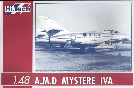
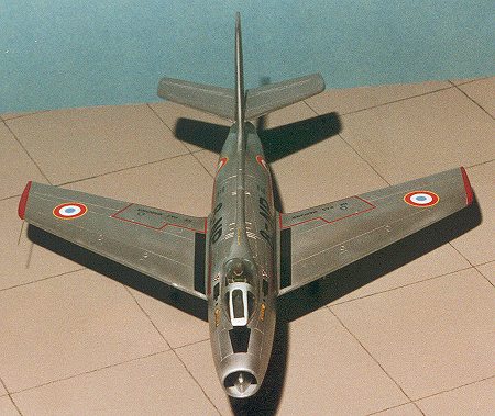
Hi-Tech 1/48 Dassault Mystere IVA
|
KIT # |
005 |
|
PRICE: |
$29.95 MSRP |
|
DECALS: |
One aircraft: EC 2/8 'Nice' |
|
REVIEW : |
|
|
NOTES: |
Multimedia kit |
|
HISTORY |
The early 1950's were a time of transition in military aviation.
Not only in the change from piston to turbojet powered aircraft, but the basic
design of fast aircraft was changing as well. This is, of course, the
introduction of swept aerodynamic surfaces in order to forestall the effect of a
huge mass of air on the airframe called 'compressibility'. This effect is what
kept most straight-winged aircraft from entering the domain of transonic speeds.
Most
successful aircraft of the period were, in effect, swept wing versions of
already successful and tried aircraft. The F-86 derived from the straight winged
FJ-1, the F-84F from the F-84G, and, the Mystere IV from the Ouragan. The French
designer Marcel Bloch, who was a successful aircraft maker pre-war and who
changed his name from Bloch to Dassault, saw the trend and, being a cautious
(and superstitious) man, waited until there was sufficient evidence that swept
wings were safe before redesigning the Ouragan.
Even as the Mystere IIC was being built, the next
generation Mystere IV was well into its flight test program. Where the Mystere
IIC was basically a swept wing Ouragan, the Mystere IV was a completely new
airframe. Despite looking quite similar to the Mystere IIC, there was not one
structural part that was interchangeable between the two. The IVA also had an
'all flying' tailplane and a thinner wing. It was first flown in September 1952.
A total of 421 were built between 1954 and 1958, 240 going to France, 110 to
India and 60 to Israel. Like all previous post war French
fighters, those going to France and Israel were fully funded by the US under
what was known as Off Shore Procurement, a program designed to get those
industries that were destroyed in the war rebuilt and back under way.
Mystere
IVs were used in the Suez War of 1956 and had a very long and successful life.
Even after being withdrawn from front-line service, they went on serve as
advanced training aircraft. EC 7 had a number of them on hand even after
transitioning to Jaguars. EC 8 used them as fighter trainers, the last ones
leaving service in December 1982. Not bad for an aircraft that was then nearly 30
years old. Today, there are a number of them extant as museum aircraft and at
least one is still airworthy and flown on occasion. 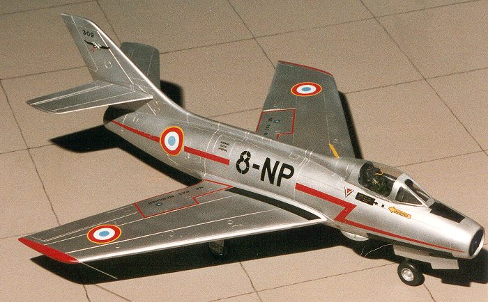
 As was to
be expected, the Mystere was just as reliable and successful as the
preceding Ouragan. Its first flight was in February of 1951, and based on
tests, the French government ordered 17 development aircraft as Mystere II's.
These were successful and based on this aircraft, a batch of 156 Mystere IIC's
were built. The major change was a more powerful Atar 101D engine and the
inclusion of twin 30mm DEFA cannon. The aircraft was a major surprise to those
outside France who flew it. It was also quite fast, able to break Mach 1 in a
dive.
As was to
be expected, the Mystere was just as reliable and successful as the
preceding Ouragan. Its first flight was in February of 1951, and based on
tests, the French government ordered 17 development aircraft as Mystere II's.
These were successful and based on this aircraft, a batch of 156 Mystere IIC's
were built. The major change was a more powerful Atar 101D engine and the
inclusion of twin 30mm DEFA cannon. The aircraft was a major surprise to those
outside France who flew it. It was also quite fast, able to break Mach 1 in a
dive.
|
THE KIT |
This kit is a true multimedia presentation. It has it all:
injected styrene, resin, etched metal, cast metal and vacuform! The initial
feeling upon opening the box is one of getting your money's worth, especially
when looking at the big bag of resin parts! It is then time to take a closer
look as what is in the box itself. After pulling out all the bits, one notices the injected parts.
The detailing on them is very good. Nice and crisp without the rounded edges
given in a number of similar kits. This crispness carries over to the resin
parts as well. One does also see that there is a bit of flash on the parts and
that it will be fun getting the intake properly rounded out. The other bag contains a bunch of resin parts. Some of these are
quite large and heavy and I was fearful of finding a lot of broken parts, but
fortunately, only the cockpit antiglare shield suffered any damage. Parts done
in resin consist of: nose section which contains the nose gear well, and
cockpit. This part should be heavy enough to negate the need for nose weight as
there is really nowhere to put any! Getting back to the resin parts, there are
main gear wells and speedbrake wells, the gear doors themselves, speedbrakes,
ejection seat, gun bulges, exhaust pipe, cockpit antiglare panel, tailplanes,
and the wheels. Whew!! There is also a vacuform canopy. Again, just one. I do
wish these folks would pop an extra in the kit for those of us who are a bit
klutzy and may need a spare. The instruction sheet is basically a sheet of paper folded in
half making four pages. The opening page is a history in two languages. It
offers a lot of info and insight into the version of the Mystere IVA that is
kitted. The next two pages are two assembly steps. The last page is a decal
placement diagram and painting notes. The aircraft is overall aluminum with a
number of flat black areas, so those that don't like natural metal don't have to
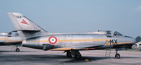
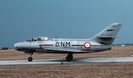
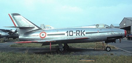
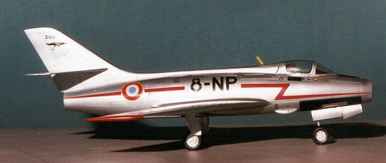
worry about this one. Just to give you an idea of the various marking schemes that the
Mystere IVA carried, here are some photos taken from my personal archives. All
were photographed in the 1970-1980 time frame. You can see from 8-MX the final
placement of the codes prior to the retirement of the type in December 1982. EC 8 was the
last unit to use them.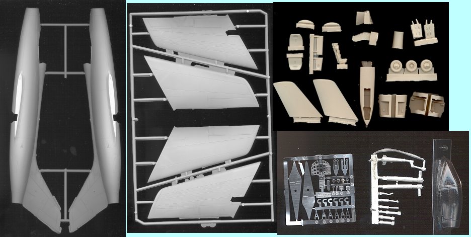
 Next I opened the bag containing the etched and cast metal
parts. These parts are well done, though the cast metal bits will need some
cleanup. These parts are basically the landing gear and the control column. The
etched parts did not fare too well being in the bag with those heavy cast parts
and were rather well bent by all the jostling about on its trip from France via
Texas to here. These parts consist of oleo scissors, door hinges, instrument
panel, rudder pedals, and tailplane plates as well as a few other bits.
Next I opened the bag containing the etched and cast metal
parts. These parts are well done, though the cast metal bits will need some
cleanup. These parts are basically the landing gear and the control column. The
etched parts did not fare too well being in the bag with those heavy cast parts
and were rather well bent by all the jostling about on its trip from France via
Texas to here. These parts consist of oleo scissors, door hinges, instrument
panel, rudder pedals, and tailplane plates as well as a few other bits. 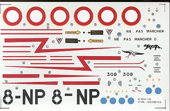 The decals are
for just one aircraft and are very complete. They are also VERY matte, off
register, and not as crisp as the typical aftermarket sheet. This is a shame as
one is not likely to find any aftermarket sheets for this aircraft. The biggest
problem is finding new roundels as the thin yellow surround is badly off
register. I can only hope that I can find substitutes somewhere in my spare
decal boxes. It would have also been nice to have had an alternate scheme or
two, but I do understand why not as it would have meant producing several
different designs and colors of fuselage striping.
The decals are
for just one aircraft and are very complete. They are also VERY matte, off
register, and not as crisp as the typical aftermarket sheet. This is a shame as
one is not likely to find any aftermarket sheets for this aircraft. The biggest
problem is finding new roundels as the thin yellow surround is badly off
register. I can only hope that I can find substitutes somewhere in my spare
decal boxes. It would have also been nice to have had an alternate scheme or
two, but I do understand why not as it would have meant producing several
different designs and colors of fuselage striping.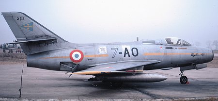
|
CONSTRUCTION |
First step is parts preparation. In this case, it meant cutting all the styrene parts off the sprues and cleaning them up. A very close look at the parts shows a myriad of very small depressions on the plastic, giving it a pebbly finish. Hopefully this will disappear under a few coats of primer. The gates are relatively large and care was taken when sawing off the parts. There was also a lot of flash to clean up. The mating surfaces are uneven and need sanded down. There is clean-up needed in the wheel wells, cockpit and the nose intake. Make no doubt about it, this is a limited run kit and needs to be treated as such. If you try to slap this one together like a mainstream injected kit, you will be regretting it. It took a lot of work to sand the nose intake to something resembling the prototype. I used 180 grit paper wrapped around a wooden dowel to get the shape correct.
 Next, I removed all the resin
bits that are initially needed from their blocks. This includes the cockpit, the
main wheel wells and the wheels. These needed some sanding down as well. The
resin used on this kit is not like what we get in the US. It is has a sort of
'soapy' feel to it. It doesn't seem as brittle, either. I had to do some hefty
sanding on a seam in the intake/cockpit section and it didn't bring about a rash
of air bubbles as I had feared. Make sure that ALL parts are dry fitted several
times before committing them to glue.
Next, I removed all the resin
bits that are initially needed from their blocks. This includes the cockpit, the
main wheel wells and the wheels. These needed some sanding down as well. The
resin used on this kit is not like what we get in the US. It is has a sort of
'soapy' feel to it. It doesn't seem as brittle, either. I had to do some hefty
sanding on a seam in the intake/cockpit section and it didn't bring about a rash
of air bubbles as I had feared. Make sure that ALL parts are dry fitted several
times before committing them to glue.
First thing I did was to glue the wings together. These are completely without any alignment pins at all. In fact they are basically two thick slabs of plastic! When gluing them together, try to get plastic to ooze out of the joins. This will save you having to use a lot of filler on the edges.
 Next it was time to fit some
resin bits in the fuselages. The nose piece fit rather well with minimal fuss.
Make sure that the intake is square or it will be impossible to fix later!
Same with the exhaust. I had to glue plastic card to the back of the exhaust in
order to get it centered in the fuselage. It is actually smaller in diameter
than the aft hole so needs extra effort to be properly centered. See image to
the right.
Next it was time to fit some
resin bits in the fuselages. The nose piece fit rather well with minimal fuss.
Make sure that the intake is square or it will be impossible to fix later!
Same with the exhaust. I had to glue plastic card to the back of the exhaust in
order to get it centered in the fuselage. It is actually smaller in diameter
than the aft hole so needs extra effort to be properly centered. See image to
the right.
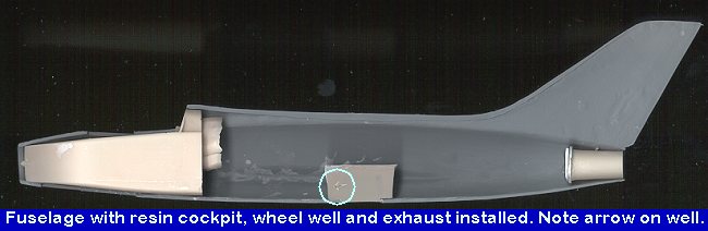
Speaking of extra effort, we come to the resin wheel wells. These things were a lot of work to get to fit. I removed plastic from the fuselage and resin from the wells themselves before I got a decent fit. Then I had to sand the back of the wells to get the fuselage halves to fit. All of this fussing took several hours. There are arrows showing the front of the aircraft so that you don't get the wells in backwards. I took the coward's way out and didn't remove the air brakes! Once those were firmly in place, the fuselage halves were glued together. I wasn't able to sand enough off the wheel well inserts as I was starting to break through the resin walls. This left about a 1/16" gap that had to be filled with superglue.
Once the fuselage was
together, the seams were filled with either superglue or filler, depending on
where they were. It took several sessions to get it properly smooth. The next
parts to glue on were the wings. These had already been glued and
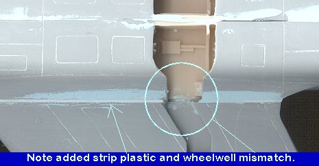 smoothed prior to assembly. It was
then that I noticed a rather big error. The wheel wells would not line up. One
has a choice here, either to line up the wings with the wing roots and suffer
with the well mismatch, to line up the wells and then redo the wing roots, or to
remove the wheel well section from the lower wing and reposition it. Since I had
already glued the wing halves together, the final option was out. I decided to
bite the bullet and leave the wells misaligned. No model contests for this one!
smoothed prior to assembly. It was
then that I noticed a rather big error. The wheel wells would not line up. One
has a choice here, either to line up the wings with the wing roots and suffer
with the well mismatch, to line up the wells and then redo the wing roots, or to
remove the wheel well section from the lower wing and reposition it. Since I had
already glued the wing halves together, the final option was out. I decided to
bite the bullet and leave the wells misaligned. No model contests for this one!
The wings were then glued on. It is a butt join, but with so much area and the soft plastic, I didn't feel as if any reinforcements were needed. Naturally the wings were thicker than the wing root so I put most of the overhang on the bottom along with the off center wheel wells. The wings also took a shim of strip plastic on the bottom. After nearly a week of applying filler and smoothing it down, there is a good wing/fuselage join.
Next to be added were the tailplanes. These are resin and have etched metal plates that go between them and the fuselage. There is a hole in the tail to help align things. What I did was to drill out the hole with a #61 drill bit. This allowed me to fit a section of paper clip in there. The etched brass bits then fit over the paperclip and were superglued to the tail. Actually, these should have been glued to the tailplanes, but I couldn't get the tailplanes to match the curve of the tail and was worried about making the tailplanes too short. I then matched up the tailplanes to the etched metal piece and marked on them where the metal rod was. Then a hole was drilled in the tailplanes with a #61 drill bit and the tailplanes then superglued onto the rod. The end result is pretty good.
 Landing gear were next on the
agenda. They are white metal and a bit soft so can be bent without too much
trouble despite their thickness. Good thing, too as they were a bit warped.
After straightening them out, they were cleaned up and glued into place. The
main gear don't look the same as in the instructions and the instructions are
not too clear about where they should go. I placed them to the front of the well
on the outside. This also helped ensure a good, tight gluing. The nose gear I
put near the rear of the well. There are shocks that attach to the gear legs. If
I read the instructions right, one is supposed to make a portion of them from
stretched sprue. Well, to heck with that as it won't do a thing for the
sturdiness of the assembly. I placed them in closer so that I could get a good,
strong bond.
Landing gear were next on the
agenda. They are white metal and a bit soft so can be bent without too much
trouble despite their thickness. Good thing, too as they were a bit warped.
After straightening them out, they were cleaned up and glued into place. The
main gear don't look the same as in the instructions and the instructions are
not too clear about where they should go. I placed them to the front of the well
on the outside. This also helped ensure a good, tight gluing. The nose gear I
put near the rear of the well. There are shocks that attach to the gear legs. If
I read the instructions right, one is supposed to make a portion of them from
stretched sprue. Well, to heck with that as it won't do a thing for the
sturdiness of the assembly. I placed them in closer so that I could get a good,
strong bond.
Next was the cockpit. This needed the instrument panel, rudder pedals, and control stick added. The etched instrument panel fits onto a solid piece that includes the anti-glare shield. There is no clear set of dials to add to it as is provided with some other kits. The rudder pedals are etched metal and need to be bent into position. They fit on a rod that was made from stretched sprue. A hole was drilled into the spot marked on the resin panel and the rod threaded through it. The pedals need to be right up against the inside of this resin panel or they won't fit in the cockpit. This piece was then glued into the cockpit. The metal control stick was glued in place and the whole interior painted flat black.
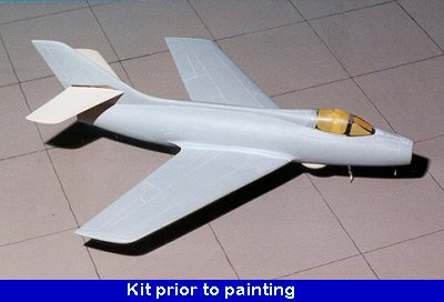
 While this was drying, I
trimmed the vac canopy to fit. Naturally it is narrower than the cockpit
opening. What this tells me is that I needed to sand both fuselage halves down
about another 1/16th inch each to get this canopy to fit. However, to do this
would have made it nearly impossible to glue in the cockpit, never mind the
already too large fuselage wheel wells! I can only hope to be able to keep the
canopy spread far enough apart while the glue sets!
While this was drying, I
trimmed the vac canopy to fit. Naturally it is narrower than the cockpit
opening. What this tells me is that I needed to sand both fuselage halves down
about another 1/16th inch each to get this canopy to fit. However, to do this
would have made it nearly impossible to glue in the cockpit, never mind the
already too large fuselage wheel wells! I can only hope to be able to keep the
canopy spread far enough apart while the glue sets!
Before attaching the canopy, I had to paint the ejection seat. All the instructions stated were that it was black. Well, I'm pretty sure there was a bit more to it than that! The seat cushions were painted in dark green and the little etched handle was done in yellow. The seat was test fit into the cockpit and found to sit too low. A piece of scrap resin was glued to the bottom of the seat and then sanded down until the seat looked to be the right height. A small piece of wire was used for the face curtain handle and painted yellow. After drybrushing the seat and cockpit, the seat was then glued into the cockpit.
Now for attaching the vac canopy. The canopy itself is molded well except for the lower edges. Here it looks as if they ran out of mold as it is quite lumpy and rough. Since chances of getting an aftermarket canopy are zilch, one needs to do what one can with what is available. It was glued onto the fuselage in stages using non-fogging superglue. When dry, more glue was applied to the outer edges to help seal gaps. This was then gently sanded and the final result doesn't look too bad.
|
PAINT & DECALS |
Before
applying decals, I decided to do some work on the landing gear and wheels. The
gear oleos were covered with chrome Bare Metal Foil. Then the oleo scissors were
applied. These beasts are each a two piece construct. Why they are not a single
piece that you bend is beyond me. It also didn't help that I lost one of the
halves! This means that I have to make a decision about the nose gear before
completing the kit. The decals are very thin and very flat. They
are also not the best in terms of quality as my set had a lot of blue dots
splattered on the red side lightning bolt. There was also some registration
problems, probably with the yellow, that made the roundels unusable. However, I
had no choice but to use them as there are no real aftermarket sheets for French
Mystere IVs. The decals themselves are semi-transparent, so it is good that I
was putting them on a solid, light surface. They did fit quite well and snuggled
into all the cracks and crannies. I had to use roundels gleaned from my spare
decal sheet box. It is situations like this that these spare bits boxes come in
very handy!! The wing walk areas were made from Superscale solid sheet decals.
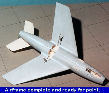
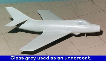 Now that I had a basically complete airframe, it was time to do
some painting. The first part painted was the canopy. This was painted black so
that this color would show on the inside. Since a metallic was to be painted on
the plane, the aircraft was sprayed with a coat of gloss light grey. I had some
Testors Modelmaster Voodoo Grey enamel that I used. This showed up the really
poor surface of the kit. The thing looks like someone walked over all of it with
golf cleats. To get a smooth surface will take MANY coats of paint or much
sanding. Being lazy, I just sprayed on a couple of more coats of paint until it
looked a bit less lumpy. The engraved panel lines are large enough that all this
painting did not fill them up. Then the kit was sprayed overall with aluminum
Metallizer. Boy, did that show up the quality of the plastic and resin pieces!
Now that I had a basically complete airframe, it was time to do
some painting. The first part painted was the canopy. This was painted black so
that this color would show on the inside. Since a metallic was to be painted on
the plane, the aircraft was sprayed with a coat of gloss light grey. I had some
Testors Modelmaster Voodoo Grey enamel that I used. This showed up the really
poor surface of the kit. The thing looks like someone walked over all of it with
golf cleats. To get a smooth surface will take MANY coats of paint or much
sanding. Being lazy, I just sprayed on a couple of more coats of paint until it
looked a bit less lumpy. The engraved panel lines are large enough that all this
painting did not fill them up. Then the kit was sprayed overall with aluminum
Metallizer. Boy, did that show up the quality of the plastic and resin pieces!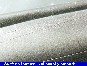 Once the paint was dry, there are
several areas that need to be painted black. These were masked off and painted
as were the wing tips which were painted red. I then repainted several areas
that I noticed had thin paint. Then the entire kit was sprayed with clear
acrylic gloss in preparation for continued construction and decals.
Once the paint was dry, there are
several areas that need to be painted black. These were masked off and painted
as were the wing tips which were painted red. I then repainted several areas
that I noticed had thin paint. Then the entire kit was sprayed with clear
acrylic gloss in preparation for continued construction and decals.
|
CONSTRUCTION |
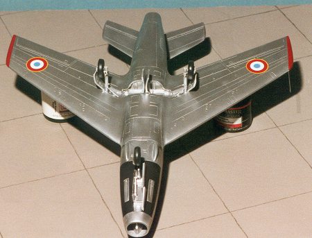
On to finishing up the kit. At this time I put on the resin wheels, which
were already painted. The wheel attachment points had to be drilled out a bit
more and I ended up cutting off most of the wheel axle as they were way too
long. Better long than too short. The front wheel was made ready to install, but
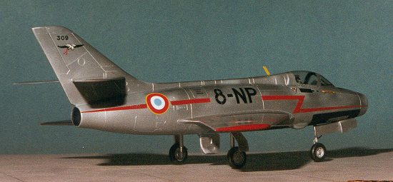
left off until later. The axle for the front wheel is much too skinny. In fact,
the front wheel looks too large for the aircraft. It is about the same diameter
as the main wheels and as you can see from the pictures above, it is
considerably smaller. Before attaching the front wheel, I cut an oleo scissor
from scrap etched metal and glued it in place.
The
last things to put on were the etched metal antenna and the pitot tube. The tube
was made from stretched sprue. A hole was drilled in the wing tip and the pitot
glued in. The metal antenna was glued on the spine and then painted yellow. A
bit of touchup painting was done and the kit was sprayed with clear gloss to
seal the decals. Then the black areas were sprayed with matte clear. When dry
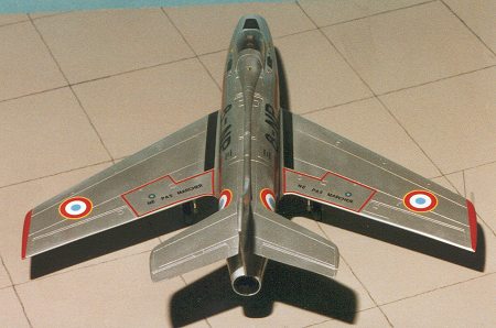
the tape was removed from the canopy and the kit was done. 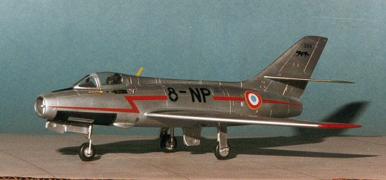 Next, the gear
doors were attached. The main gear doors are supposed to be in the up position,
but I forgot to do that and besides, the doors are too large for the openings.
By slightly bending the hinges, gluing them was very easy. The front doors have
the hinges as part of the door so don't goof up and cut them off when removing
them from the resin block! You can glue the front one in the up position should
you desire, but you don't have to (see pictures above). These were attached with
superglue. The main gear doors were glued to the wing.
Next, the gear
doors were attached. The main gear doors are supposed to be in the up position,
but I forgot to do that and besides, the doors are too large for the openings.
By slightly bending the hinges, gluing them was very easy. The front doors have
the hinges as part of the door so don't goof up and cut them off when removing
them from the resin block! You can glue the front one in the up position should
you desire, but you don't have to (see pictures above). These were attached with
superglue. The main gear doors were glued to the wing.
|
CONCLUSIONS |
What initially looked like a simple kit turned into a very
challenging build. All of the glitches mentioned in the review can be overcome,
though the wing/wing root problem is one that will take the most effort to get
the gear wells to line up. Had I spent more time with the sandpaper, I could
have sanded the surface smooth as the panel lines are deep enough to handle all
the sanding that will be required. Being a coward, I did not do the opening
speed brakes. Looking back, I'm glad I didn't. The instructions also turned out
to be of very little real value when it came to building the kit. They just
don't offer enough information to be of any help. Because of all
the problems that need to be overcome and the poor instruction sheet, I can only
recommend this kit to those who are experienced with short run kits and are
willing to put in the extra work to make it right. The kit does make into a very
nice model when done and it is something that you won't see every day!
REFERENCES Illustrated Encyclopedia of Aircraft #181, Orbis
Publishing. Air Forces International, June 1989 July, 2000 Copyright ModelingMadness.com.
All rights reserved. No reproduction in part or in whole without express
permission from the editor. If you would like your product reviewed fairly and fairly quickly, please contact the editor or see other details in the Note to
Contributors.
Back to Reviews Page 2016