AZ Model 1/48 Kellet YG-1B
| KIT #: | AZ 4829 |
| PRICE: | $60.25 |
| DECALS: | Three options |
| REVIEWER: | Scott Van Aken |
| NOTES: | Short run kit with photo etch and acetate parts |
| HISTORY |
Using the experience gained in building Cierva autogyros under licence the Kellett Autogiro Company developed the KD-1 which was similar to the contemporary Cierva C.30. It had two open cockpits, a fixed tailwheel landing gear and was powered by a 225hp (168kW) Jacobs L-4 radial engine. After testing of the prototype a commercial variant designated theKD-1A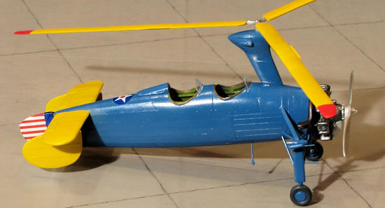 was put into production. The KD-1A had a three-bladed rotor with folding blades and a number of minor detail improvements. A KD-1B which was a KD-1A with an enclosed cockpit for the pilot was operated by Eastern Airlines and inaugurated the first scheduled rotary-wing air-mail service on 6 July 1939.
In 1935 the United States Army bought a KD-1 for evaluation and designated it the YG-1, a second aircraft followed which had additional radio equipment and was designated the YG-1A. These two aircraft were followed by a batch of seven designated YG-1B. In 1942 seven more were bought for use in the observation role as the XO-60. Six XO-60s were re-engined with 300hp (224kW) Jacobs R-915-3s and re-designatedYO-60. One YG-1B was modified with a constant-speed rotor and was re-designated theYG-1C, it was later re-engined with the more powerful R-915 and re-designated again as the XR-2. The XR-2 was destroyed by rotor ground resonance problems and the evaluation was continued with another modified YG-1B designated the XR-3.
Imperial Japanese Army developed the Kayaba Ka-1, referring to KD-1A. Powered by a 240hp (179kW) Argus As 10 engine, Airframe that changed engine of prototype.
| THE KIT |
Molded in AZ's usual tan plastic, I found that the quality of the molding is actually very good. I found no sink areas, no flash, no nasty ejector pin marks and no problems with mold mis-match. This is good. A nicely done photo etch fret includes a number of small parts, many for the interior as well as two external plates for the Navy version. Resin is provided for the seats, prop, engine, exhaust, wheels, and a scoop of some sort. Casting on these parts is superb with almost no molding glitches aside from a small air bubble or two. Also included are two acetate instrument sections to fit behind the etched panels in the cockpit. Parts for the 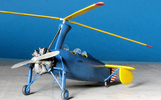 Kayaba Ka-1 (the engine cowlings) are not used.
The kit has a very complete interior with floor, seats, control sticks and rudder pedals. Some of these parts are photo etch. AZ models provides full painting information during construction, though I'm not sure if chromate green would be appropriate for this aircraft as unpainted aluminum was more the norm before the war. The interior includes a nicely molded frame work that is installed on the sidewalls.
As you can imagine, the landing gear struts are going to be a bit fiddly, but AZ provides several drawings to help getting everything properly aligned. A few areas require the builder to stretch some sprue, but that is the norm for many short run kits. The rotor blade attachment is a butt join. I'd drill outthe blade ends at a minimum and perhaps find some wire to insert in the blade and hub for a more secure join. The kit does not include the windscreens, nor does it provide a template so you are on your own in that regard.
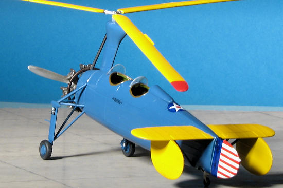
Markings are provided for three aircraft. You have a civilian KD-1 in red and cream, an Army YG-1 in OD with yellow tail surfaces and a similar one with a blue fuselage and yellow tail surfaces. The kit decals are your only option for something like this and they look to be well done. Instructions are also nicely drawn and provide quite a bit of information to help build this one.
| CONSTRUCTION |
This one has been sitting on my 'to do' pile for many, many months and so I decided to toss caution to the wind and give it a go.
Bowing to convention, I removed many of the parts and started cleaning them up. The cockpit section has resin seats balancing precariously atop two rather thin horizontal plastic framework pieces. Careful sanding got a flat mating surface and once tacked on, the joins were liberally reinforced with super glue. The rudder pedal situation is odd as the fret only supplies one set of etched pedals, which are a totally different design to the plastic on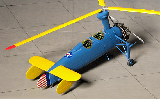 es. Regardless, I installed those puppies in the front using the standard plastic ones in the back. I then glued the side framework where it looked like they would fit on the outside of the cockpit floor. I glued them at a bit of an outward angle as the plastic AZ Model uses is soft, but pretty flexible.
Next in the build was the installation of the belts. Again, the fret offers a full harness set, but only for one seat. It seems that someone screwed up when it came to the fret by not realizing that this was a two seat aircraft. Certainly not the sort of treatment one would give a $60 kit. Still, I split the belts between the two seats as my understanding is that a shoulder harness was not standard stuff until the early 1940s. Meanwhile, I painted the instrument panels and then attached the acetate instruments to the back. Later, the control sticks were glued in after enlarging the attachment holes.
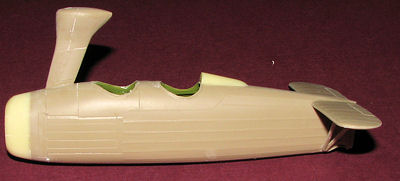
All of the interior bits and the inside of the fuselage were then painted interior green, despite my misgivings about the color. When dry, I test fit the interior. To say it doesn't fit would be about right. It is too wide. Trouble is, if one narrows things down to where fit isn't an issue, then one would have to either leave out the framework and trim the floor sides or cut the sides away from the seats (and trim the floor sides as well). I decided to leave the huge gap and fill it when it came time to join the halves.
Meanwhile, I glued in one side of the interior and taped the other fuselage half in place. There are no alignment indicators so one just has to wing it. Once the interior was in place, I went to see if the instrument panels fit. I had my doubts and those were verified. Not only were the panels too wide, but they were too tall. I trimmed the dickens out of them to get them to fit atop the framework and slathered super glue behind them to help keep them in place. Good thing too, as when I attached the other fuselage half, they bent as they were still too wide.
S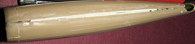 o I carefully glued the upper part of the fuselage together, taping it as I glued. When it came to the underside, the fuselage only joined at the very front and very rear. I used super glue for that then started filling in the gaps with plastic card and super glue. as you can see from the image, it was not pretty, but sanding and scraping can cure all sorts of issues.
Eventually it was looking pretty good so I then added the resin nose cap and the aft cockpit head rest. Fit for both was not bad. Next step was the glue on the rotor pylon. While doing this I noticed that both fuselage halves were not symmetrical. Though the cockpit openings matched, one side was higher than the other and there was a small step at the very rear. This made it somewhat difficult to attach the pylon as the left side was pretty flat while the right side sloped away more. Again, super glue to the rescue.
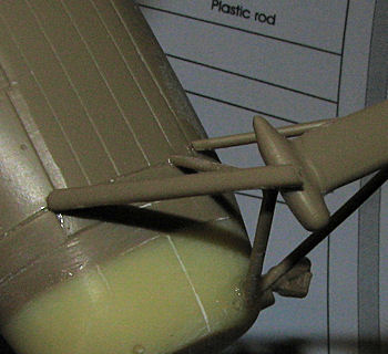
 At the back, I glued on the tail planes. Though the instructions show the fins to be attached next, I decided to glue on the rear V struts. If one glues the struts to the holes on the stab, the fuselage attachment point is too far forward. So I cut away the attachment lug on the V strut, glued it behind the supplied hole and filled in the hole. Makes me wonder what the gear assembly was going to be like.
Well, main gear assembly is not simple. For a starter, there are three holes that need to be available on the fuselage. An upper one for a strut and two very low down. One of the lower holes has to be on the resin nose section, so that has to be drilled. The very low hole that you can see on the previous image is too low down so that was filled and drilled higher up. The very bottom v strut has no pins to fit into fuselage holes and butt joins.
 The important v strut is the smaller one. Once that is in place, all the rest can simply be attached accordingly. The more I work on this kit the more I am disgusted by how poorly the instructions are for this one. Fit is one thing, but having to constantly look at drawings and the box art to figure out what goes where totally sucks. Not only that but there are parts that it turns out fit better on the right or left side of the aircraft and both pieces have the same part number. This kit is a case of fit several times, adjust things and then cement. After considerable drilling and adjusting, I got the major part of the landing gear in place. There is an upper brace, but as luck would have it, it is far too long. Snip, snip, glue and it was in place. Looking at the results of all this from dead on shows things are not quite symmetrical, but hey, it is a short run kit and it looks OK.
moving to the back, the vertical fins were glued in place. Might as well cut away the rear pin/sprue attachment point as it will not match up with the hole provided for it. With those in place, the rudder was glued on. At the prop blades, the small photo etch trim tabs were glued on. I then stuffed the cockpits with tissue and headed for some paint.
| COLORS & MARKINGS |
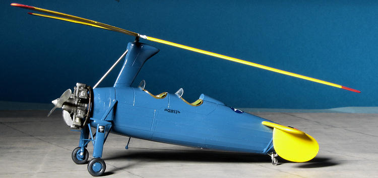
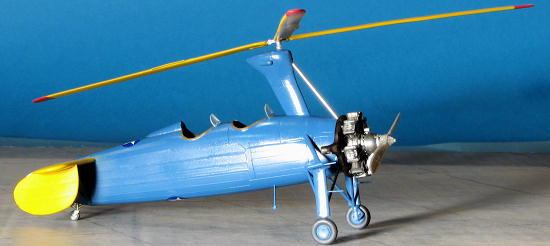
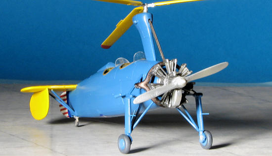 I had already decided on the box art scheme as I like blue fuselages. The tailplanes and the prop blades were painted white prior to painting them with an appropriate yellow. I used Insignia Yellow on these as it seems perhaps these planes were initially made for the USAAC. All of that stuff was then masked off and were I to do another of these kits, I would leave off the tailplane struts until after painting. The rest of the fuselage was painted Pollyscale Blue 23 acrylic. When dry, a coat of Future was sprayed on.
I then attached the minimal decals. These decals are very thin, do not like to move once applied and tear very easily. This resulted in my having to do patch painting on the rudder stripes. Besides, the rudder stripes do not have any 'wrap around, you one will end up painting the bare plastic bits around the edges anyway. Fortunately, it seems the paints I used matched pretty well. During this process I noticed that the rear cockpit head rest is about twice as long as it needs to be. Those of you foolish enough to build this kit will want to cut it in half and just use the rear portion.
| FINAL CONSTRUCTION |
Using patience and super glue, the tail wheel assembly was glued in place. The main wheels went on without any trauma. This kit requires some additional pieces that are not included or are poorly represented. There is a drive shaft that goes from a hidden gearbox in the engine accessory section to the main rotor. This has to be provided. I used a section of stainless steel tubing for this. Drilling the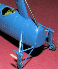 openings at the proper angle will take patience, but it can be done. Then there is a pod on the right gear leg that needs to be installed. There is no part number shown for this in the instructions, but the only thing close is a half of a teardrop shaped piece. It turned out that this piece needed to go atop the rotor pylon. I ended up sanding down a section of sprue to replicate this. There is a small section of rod used to attach it to the gear leg. The tip needs to be drilled out for another small section of rod. Same for two rod protrusions from the front the gear legs. I am going to go out on a limb and assume that these are steps of some sort for maintenance people. I used .020 bronze wire for these as the stuff is rigid and easily cut with side cutters. One can also sand the ends flat after cutting with some ease. If you look at the small accompanying image, you can see these bits prior to painting. I also used this wire for the post for the antenna wire. To duplicate the bulb at the end that is shown in the box art, I simply dripped some clear paint and let it dry. This post is shown as part 31, but there is no part 31 on the sprues.
Next is engine installation. This was also problematic. There is what I assume is a carb intake duct that fits in between the lower two cylinders. The instructions are rather vague on how this fits. The instructions show the exhaust exiting at the lower left of the fuselage while the box art shows it at 90 degrees on the left side. While on the subject of engines, the civil markings would require the engine to have one of those cooling covers over it such as you see on an F4B-4. None is included with the kit.
So I went with the box art and glued the collector to the back of the engine, then cementing the engine in place about the center of the firewall. The intake duct was test fit and found to need some work. The forward end attaches to the gear box housing which is conical. The mating surface on the duct is flat. Some carving and sanding later, this piece was installed.
 The last major piece to attach is the rotor. I drilled out the ends of each blade to accept the stub from the hub. I also noticed that the instructions would have you install the blades in what I think is upside down. The blades do have an airfoil section and the installation procedure would have the flat part of the airfoil on the top. According to images of the real aircraft and the shape of the blade tips, the instructions are correct. The blades had the small photo etch trim tabs glued to them and were painted yellow with red tips. There is no droop to these blades and those wanting more accuracy will need to do that.
With that painted, it was time to work on windscreens. The kit acetate sheet did not have any on it as implied in the instructions. What I did have was a similar windscreen that was left over from some other kit, but I needed a second. I had a car vac windscreen that I used to cut the second windscreen. It was not as curved as needed, but close enough. These two items were held onto the fuselage using clear gloss acrylic paint. I let the paint get sort of tacky before setting the screens into it. When dry, several additional applications were used to hopefully hold these in place.
Finally, the opening for the rotor blade had an extension glued into it using a piece of sprue. This was then drilled out for the blade assembly. Without doing this, the rotor blades would be flat atop the pylon when they should jut up quite a bit. The opening in the top of the pylon is far too large. Finally, the prop was glued in place, EZ-line used for the radio antenna, and the project was done.
| CONCLUSIONS |
I am not sure if this is the first AZ kit I have built or not, but it certainly lived up to its jaded reputation. The instructions are no more than a general guide and a lot of work has to be done to match how the aircraft should look. While the end result is worth the effort to me, to many it may well not be. I can only recommend this kit to those who are comfortable with modification and scratch-building parts. To prepare for it, I would recommend a root canal.
| REFERENCES |
 http://en.wikipedia.org/wiki/Kellett_KD-1
February 2012
Copyright ModelingMadness.com. All rights reserved. No reproduction in
part or in whole without express permission from the editor.
If you would like your product reviewed fairly and fairly quickly, please contact the editor or see other details in the