Chorozny Modelbud 1/72 Mitsubishi Ki-18
| KIT #: | A 104 |
| PRICE: | @ $27.00 |
| DECALS: | One option |
| REVIEWER: | Scott Van Aken |
| NOTES: | Resin kit |
| HISTORY |
 The superlative performance of the
Ka-14 (A5M 'Claude' prototype) gained the interest of the IJAAF which
ordered a similar aircraft under the designation of Ki-18. It was identical
to the A5M except for the engine and the removal of the carrier equipment.
Tested by Army pilots at Tachikaway, it was 28 mph faster than the Ki-10
biplane that was entering service, but, because it was a monoplane, was not
as good a dog fighter. This resulted in the Army losing interest in the
type and requesting a more maneuverable aircraft. This follow-on
aircraft was the Ki-33 which lost out to Nakajima's Ki-27 in comparison
tests.
The superlative performance of the
Ka-14 (A5M 'Claude' prototype) gained the interest of the IJAAF which
ordered a similar aircraft under the designation of Ki-18. It was identical
to the A5M except for the engine and the removal of the carrier equipment.
Tested by Army pilots at Tachikaway, it was 28 mph faster than the Ki-10
biplane that was entering service, but, because it was a monoplane, was not
as good a dog fighter. This resulted in the Army losing interest in the
type and requesting a more maneuverable aircraft. This follow-on
aircraft was the Ki-33 which lost out to Nakajima's Ki-27 in comparison
tests.
| THE KIT |
 This is a complete resin kit with a
full interior and framework. No options are provided as this is, after all,
a prototype of which only one aircraft was built. The resin is well
detailed though the interior sidewall detailing has a lot of trash attached
to it that makes it look much like a jumble of 'stuff' rather than distinct
framework with various boxes attached. A close inspection of the rest of
the parts shows that the general detailing is good, but not as crisply done
as some other kits I've seen. I found few glitches in terms of air bubbles
or mold flaws other than what I mentioned in terms of the sidewall detail.
This is a complete resin kit with a
full interior and framework. No options are provided as this is, after all,
a prototype of which only one aircraft was built. The resin is well
detailed though the interior sidewall detailing has a lot of trash attached
to it that makes it look much like a jumble of 'stuff' rather than distinct
framework with various boxes attached. A close inspection of the rest of
the parts shows that the general detailing is good, but not as crisply done
as some other kits I've seen. I found few glitches in terms of air bubbles
or mold flaws other than what I mentioned in terms of the sidewall detail.
The instructions are basically a few construction drawings and several views for the application of markings. No color information is given anywhere. I found during construction that several parts were not well shown and in some cases, one had to do some guess work as to actual parts placement. This is an area that could use some improvement. Decals are a common sheet that is used for all the A5M variant kits. It looks to be well printed and should perform well.
| CONSTRUCTION |
 First step with any resin kit is to
remove the resin pour stubs. The fuselage halves had no pour stubs but a
sheet of resin that attached to the lower fuselage. This meant some tedious
sanding as the usual sawing would not work. Try though I might to keep
things even, I think I over sanded a few areas as I do on a vacuform kit
and so there were gaps on the bottom when it came time to join the fuselage
halves. The fuselage halves and flight surfaces are keyed to little holes
in the adjoining part. This worked well for the fuselage. The wings each
had a tab broken off and there was so much resin detritus on the horizontal
stabs in this area that sanding them off completely was the easiest way to
handle things.
First step with any resin kit is to
remove the resin pour stubs. The fuselage halves had no pour stubs but a
sheet of resin that attached to the lower fuselage. This meant some tedious
sanding as the usual sawing would not work. Try though I might to keep
things even, I think I over sanded a few areas as I do on a vacuform kit
and so there were gaps on the bottom when it came time to join the fuselage
halves. The fuselage halves and flight surfaces are keyed to little holes
in the adjoining part. This worked well for the fuselage. The wings each
had a tab broken off and there was so much resin detritus on the horizontal
stabs in this area that sanding them off completely was the easiest way to
handle things.
The cockpit builds up of a seat,
control stick, rudder pedals and fore and aft framework. Though not shown
at all in the instructions, I guess that the instrument panels fit on the
forward framework. This then fits into the fuselage on either side of the
interior framework detail. Of course, this puts the seat way too far
forward. Attempts at moving the assembly back didn't work as that interior
framework detailing would have to be sanded away for things to fit. As I
build OOB kits OOB, I left things in the too far forward position and glued
one side to the interior. This may have caused problems when it came time
to join the fuselage halves. The halves did not fit well and even sanding
away a considerable amount of the framework was little help. I squeezed the
halves together and used accelerator to speed up the drying of the super
glue. This caused the interior t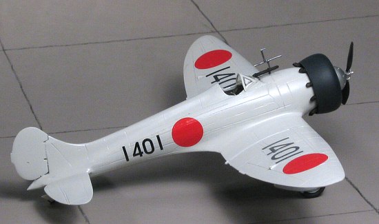 o
deform and not sit at the proper inside angle. Were I to do another of
these kits, I'd sand away the sidewall detail prior to installing the
interior and even then, I'd thin the interior bits down on the side.
o
deform and not sit at the proper inside angle. Were I to do another of
these kits, I'd sand away the sidewall detail prior to installing the
interior and even then, I'd thin the interior bits down on the side.
While this was going on, I assembled the gear legs. The front of each spat half was slightly short shot resulting in a bit of a poor fit in this area. The resin on the bottom of the spats is incredibly thin and even removing these pieces from the pour stub caused some ripping of the resin. You have to drill out the wheels quite a bit in order to get them to fit on the axle stubs, but once in there, they will turn freely. The detail on the wheels is marred by bits of junk that transferred from the mold to the resin.
With the fuselage together, it took several applications of filler to mend the seam lines. Be careful when sanding this area as it will bring out some air bubbles lying just under the surface of the resin. There is a rather unsightly dome that fits on the front of the engine. You have to take care to prep this piece so that it will fit onto the front of the engine that is provided. Basically, the join area needs to be sanded fairly thin, so take your time. You also need to take care when removing the engine cowling from the resin block. I had a terrible time getting the opening to be symmetrical and even with careful sanding was not totally successful. Again, it was a case of ultra-thin resin tearing when sawing off the pour stub.
With the cowling cleaned up, I painted the engine with aluminum and the cowling with some Blue-Black acrylic from the old Aeromaster line. I did the inside as well. I then glued the engine into the cowling once all the paint had dried. It was basically a case of fitting it in until it looked good and then applying super glue to a few of the cylinder tops from the back. I've still to install the nine separate exhaust pipes.
 Back
at the fuselage, the wings were attached. Not a great fit, but not really a
bad one either. I just made sure that I used a lot of superglue to help
fill the inevitable root seams. With the wings in place, I started by
applying some filler and alternated between filler and Mr Surfacer 500.
This allowed me a better chance to see what needed work. The key to resin
and sanding is to be gentle with the sandpaper. Often there are air bubbles
just below the surface of the resin awaiting the unwary. I ran into a few
of these on the bottom. You also have to be careful not to sand grooves
into the resin.
Back
at the fuselage, the wings were attached. Not a great fit, but not really a
bad one either. I just made sure that I used a lot of superglue to help
fill the inevitable root seams. With the wings in place, I started by
applying some filler and alternated between filler and Mr Surfacer 500.
This allowed me a better chance to see what needed work. The key to resin
and sanding is to be gentle with the sandpaper. Often there are air bubbles
just below the surface of the resin awaiting the unwary. I ran into a few
of these on the bottom. You also have to be careful not to sand grooves
into the resin.
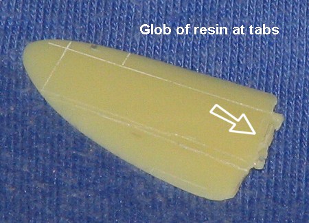
With the wings on and smoothed out, I
cut off the tabs (or lumps) on the tail planes and butt joined the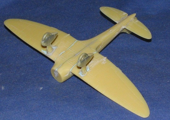 m.
These also needed filler and the same care was taken during sanding. The
rudder is a bit thinner than the
fuselage back there and also
doesn't completely match the fin profile. A bit of sandpaper took care of
the profile part and I carefully aligned it when gluing it in place.
m.
These also needed filler and the same care was taken during sanding. The
rudder is a bit thinner than the
fuselage back there and also
doesn't completely match the fin profile. A bit of sandpaper took care of
the profile part and I carefully aligned it when gluing it in place.
I then glued on the wheel spat assemblies. Fit here wasn't bad, but like many spatted models, the area around the spats needed several applications of filler to get things smoothed out. This is due to mold mismatches making one side higher than the other and chipped corners.
| COLORS & MARKINGS |
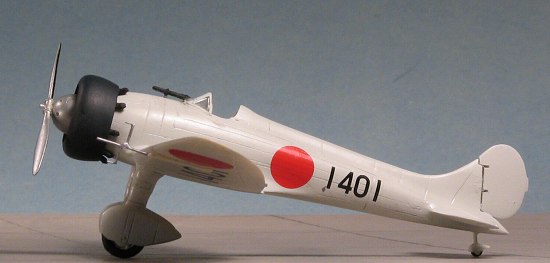
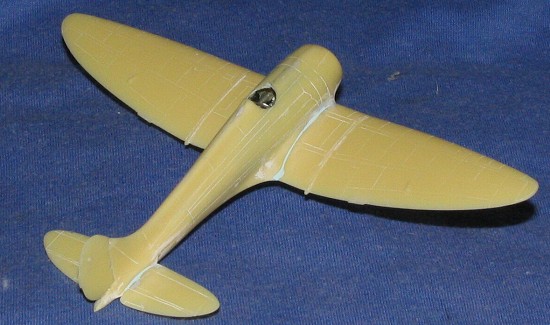
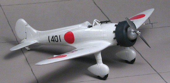
 At this stage it was time for paint.
I was at a bit of a loss as to what to paint it. The box art shows an
aluminum or light grey scheme. The folks at J-Aircraft leaned towards an
overall green-grey scheme. I stuffed tissue in the cockpit and headed for
the paint shop. I decided to go for the grey-green and used ColourCoats
excellent enamels, picking their 'underside grey-green' color. This is a
bit like a somewhat lightened RLM 02 and is somewhat darker than I had
anticipated. Not liking the shade, I then chose to use ColourCoats Japanese
Light Grey. Again, it covered very well and was given 24 hours to cure
before continuing.
At this stage it was time for paint.
I was at a bit of a loss as to what to paint it. The box art shows an
aluminum or light grey scheme. The folks at J-Aircraft leaned towards an
overall green-grey scheme. I stuffed tissue in the cockpit and headed for
the paint shop. I decided to go for the grey-green and used ColourCoats
excellent enamels, picking their 'underside grey-green' color. This is a
bit like a somewhat lightened RLM 02 and is somewhat darker than I had
anticipated. Not liking the shade, I then chose to use ColourCoats Japanese
Light Grey. Again, it covered very well and was given 24 hours to cure
before continuing.
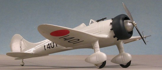
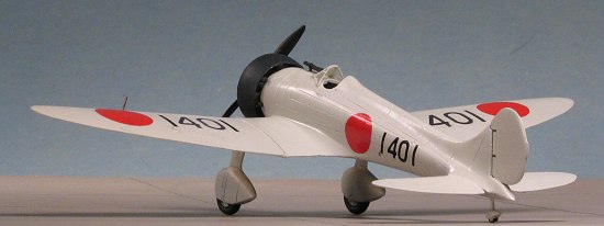
Now for the decals. The kit offers roundels and fuselage numbers. The instructions seemed to indicate that the white surround fuselage insignia was to be used, but on these aircraft, that was not done. The photo I have of this plane also did not seem to corroborate the white surround roundel. The decals were applied using Microset and worked beautifully.
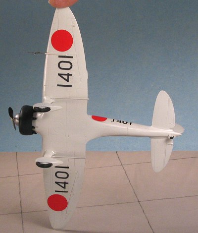
During my conversations with many on the J-Aircraft forum, it became apparent that this aircraft also had the serial numbers on the wings. It was standard procedure at the time to place the aircraft ID in large letter/numbers on the top and bottom of both wings. They would be read as looking at it from the back. Well, finding the right font was not a problem as the Japanese (who basically set up their services in a manner similar to the British), used a font that was also British. Modeldecal does several post-war letter/number sheets that use this font. My problem came from not having enough of the large size to do four sets of numbers. In fact, the size I used (24 inch) only had enough '1s' to do two full sets so I place those on the upper right and lower left side.
| FINAL CONSTRUCTION |
 Well, before dealing with the
'missing' markings situation, I thought I'd best finish up the kit. The
engine had been glued into the cowling and now for the exhaust. There are
nine small, resin exhaust stacks that need to be glued in place. No
indication at all as to where these are supposed to go. If one just cuts
them free of the resin stub and then glued them any old place on the rear
of the cylinders, there will be problems. This is because either the stubs
are not the same length of because I got the engine in crooked or the
cylinders are not the same diameter or any combination of the three. The
result was that the exhaust all stuck out from the back of the cowling at
separate heights. To make matters worse, they prevented the engine from
being able to fit on the nose of the aircraft.
Well, before dealing with the
'missing' markings situation, I thought I'd best finish up the kit. The
engine had been glued into the cowling and now for the exhaust. There are
nine small, resin exhaust stacks that need to be glued in place. No
indication at all as to where these are supposed to go. If one just cuts
them free of the resin stub and then glued them any old place on the rear
of the cylinders, there will be problems. This is because either the stubs
are not the same length of because I got the engine in crooked or the
cylinders are not the same diameter or any combination of the three. The
result was that the exhaust all stuck out from the back of the cowling at
separate heights. To make matters worse, they prevented the engine from
being able to fit on the nose of the aircraft.
There are always solutions. One was to clip all the stubs to where they were short and glue them to the inside of the cowling. In that way, they'd all be about the same height. Of course, I lost one of them , but with the use of a bit of heat and some Contrail plastic rod, I made a replacement. Next, once they were all well glued to the cowling, I took my scalpel and started scraping the inside of the pipes until they were trimmed down enough for the cowling to fit on the nose. Then they were painted Burnt Iron and set aside.
 Next, it was time for the windscreen.
Chorosny Modelbud provides two of these, which is quite nice. However, I
was to find that the side glass was not the same size on both sides which
made an even attachment difficult. I'd also suggest not cutting the lower
sides in the curve that is given or the fit will be very poor. I attached
it with white glue and hand painted the framework.
Next, it was time for the windscreen.
Chorosny Modelbud provides two of these, which is quite nice. However, I
was to find that the side glass was not the same size on both sides which
made an even attachment difficult. I'd also suggest not cutting the lower
sides in the curve that is given or the fit will be very poor. I attached
it with white glue and hand painted the framework.
I then super glued the prop onto the engine assembly and test fit it once again to the fuselage. The fit was very tight; so much so that I just left it as is without adding cement. Scrounging through the decal detritus, I found some additional decals that seemed they would work so applied additional numbers to the other wings. The last things to add are the long probe and the gun sight. The long probe had a couple of extra bits added to it with stretched sprue to more closely match the photo that I had. The forward section was painted steel and the aft bit with the light grey of the rest of the model. The kit was then completed.
| CONCLUSIONS |
 Once again, what looks like a
simple build turns out to have a few surprises. Nothing that most modelers
couldn't handle, but it wasn't the resin wonder-kit I thought it
would be when I started. I'd have to mark it as an average resin kit in
terms of overall detail and ease of build. One thing for sure, I do believe
that Chorozny Modelbud needs to work more on their instructions as I found
the part on the interior to be lacking. I also found that the drawings were
a bit contradictory. The markings drawings did not show the prototypes
large pitot, nor did the exploded views. The other drawings did as did my
photo. Those without references would have been a bit confused as to which
to use. All that aside, it is something that most of us could successfully
build and I am looking forward to giving one of their other kits a try now
that I know what to expect.
Once again, what looks like a
simple build turns out to have a few surprises. Nothing that most modelers
couldn't handle, but it wasn't the resin wonder-kit I thought it
would be when I started. I'd have to mark it as an average resin kit in
terms of overall detail and ease of build. One thing for sure, I do believe
that Chorozny Modelbud needs to work more on their instructions as I found
the part on the interior to be lacking. I also found that the drawings were
a bit contradictory. The markings drawings did not show the prototypes
large pitot, nor did the exploded views. The other drawings did as did my
photo. Those without references would have been a bit confused as to which
to use. All that aside, it is something that most of us could successfully
build and I am looking forward to giving one of their other kits a try now
that I know what to expect.
January 2005
#1346 in a series
| REFERENCES |
Japanese Aircraft of the Pacific War by Rene Francillon, second edition, 1979, Putnam
Copyright ModelingMadness.com. All rights reserved. No reproduction in part or in whole without express permission from the editor.
If you would like your product reviewed fairly and fairly quickly, please contact the editor or see other details in the Note to Contributors.