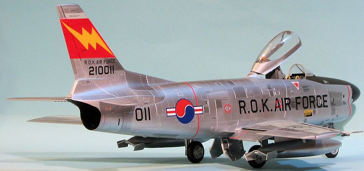
Kitty Hawk Models 1/32 F-86D Sabre
| KIT #: | KH 32007 |
| PRICE: | $109.99 SRP |
| DECALS: | Six options |
| REVIEWER: | Scott Van Aken |
| NOTES: | New tool |
| HISTORY |
The North American F-86D Sabre (sometimes called the "Sabre Dog" or "Dog Sabre") was a transonic jet all-weather interceptor of the United States Air Force and others. Based on North American's F-86 Sabre day fighter, the F-86D had only 25 percent commonality with other Sabre variants, with a larger fuselage, larger afterburning engine, and a distinctive nose radome.
The YF-95 was a development of the F-86 Sabre, the
first aircraft designed around the new 2.75-inch (70 mm) Mighty Mouse
Folding-Fin Aerial Rocket (FFAR), itself based on the German R4M rockets of
WWII. Begun in March 1949, the unarmed prototype,
50-577, first flew on 22 December 1949, piloted by
North American test pilot George Welch and was the first U.S. Air Force
night-fighter design with only a single
 crewman and a single engine, a J47-GE-17
with afterburner rated at 5,425 lbf (24.1 kN) static thrust. Gun armament was
eliminated in favor of a retractable under-fuselage tray carrying 24 unguided
Mk. 4 rockets, then considered a more effective weapon against enemy bombers
than a barrage of cannon fire. A second prototype,
50-578, was also built, but the YF-95 nomenclature
was short-lived as the design was subsequently redesignated YF-86D.
crewman and a single engine, a J47-GE-17
with afterburner rated at 5,425 lbf (24.1 kN) static thrust. Gun armament was
eliminated in favor of a retractable under-fuselage tray carrying 24 unguided
Mk. 4 rockets, then considered a more effective weapon against enemy bombers
than a barrage of cannon fire. A second prototype,
50-578, was also built, but the YF-95 nomenclature
was short-lived as the design was subsequently redesignated YF-86D.
The fuselage was wider and the airframe length increased to 40 ft 4 in (12.29 m), with a clamshell canopy, enlarged tail surfaces and AN/APG-36 all-weather radar fitted in a radome in the nose, above the intake. Later models of the F-86D received an uprated J-47-GE-33 engine rated at 5,550 lbf (24.7 kN) (from the F-86D-45 production blocks onward). A total of 2,504 D-models were built, equipping dozens of Air Defense Command squadrons in the US and many nation's air forces overseas.
On 18 November 1952, F-86D, 51-2945, set a speed record of 698.505 mph (1,124.1 km/h). Captain J. Slade Nash flew over a three km (1.8 mi.) course at the Salton Sea in southern California at a height of only 125 ft (38 m). Another F-86D broke this world record on 16 July 1953, when Lieutenant Colonel William F. Barns, flying F-86D 51-6145, in the same path of the previous flight, achieved 715.697 mph (1,151.8 km/h).
| THE KIT |
Count me as one of many modelers who have been anxiously awaiting this kit. I've always been a huge Sabre fan ever since my father took me to the end of the runway at Wheelus AFB on weekends in the very early 1950s to watch these aircraft take off and land on their way to and from weapons practice in the desert.
The box is huge as you would expect of a plane of this size.
All of the sprues are individually packaged with the clear bits coming in a
sturdy little box. The main decal sheet is huge and won't fit on the platen of
 my scanner. There is minimal photo etch, this material being used for the seat
harness and inside the speedbrake.
my scanner. There is minimal photo etch, this material being used for the seat
harness and inside the speedbrake.
Since most builds and kit descriptions start in the cockpit, so will I. The seat is made up of ten pieces, not including the p.e. This fits into a very nicely done cockpit tub that has a radio rack fixed to the back of it. The side consoles are separate bits and you can put decals over the detail already there if you so wish. Ruddder pedals are included along with a single piece control stick and throttle.
Moveing to the nose gear well, you have a choice of finned or lobed nose wheels so check your references to see which is appropriate for what you are building. The base of the nose gear well is molded into the bottom of the forward intake section. You then add the fore and side bulkheads to it with the rear bulkhead being part of the seven piece missile tray well. The kit does provide a complete intake that goes all the way to the intake compressor face of the engine.
The engine is quite complete with separate burner cans, braces and a full afterburner section. The engine comprises some forty pieces. Looking at the way the kit is designed, one could easily just build up a bare skeleton engine in order to have something to attach the intake and exhaust section to as it will be pretty well hidden once the fuselage is completed.
 The forward fuselage has two halves with a separate lower
fuselage piece that will contain each of the five piece main gear wells. The
missile tray is six parts and from the look of things is engineered to be
displayed in the lowered position. A full radar antenna is provided for the nose
section, though the instructions again show this disappearing behind the radome.
At this point, I should mention that there is no indication that any nose weight
is needed, though there is ample room for it above the intake and in front of
the cockpit.
The forward fuselage has two halves with a separate lower
fuselage piece that will contain each of the five piece main gear wells. The
missile tray is six parts and from the look of things is engineered to be
displayed in the lowered position. A full radar antenna is provided for the nose
section, though the instructions again show this disappearing behind the radome.
At this point, I should mention that there is no indication that any nose weight
is needed, though there is ample room for it above the intake and in front of
the cockpit.
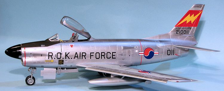
There is a separate tail section, though I'm not sure why, though it may have to do with mold size limitations or the fact that if Kitty Hawk wants to do an F-86K, they would only have to mold new forward fuselage sections. All the flight surfaces have separate control surfaces and it appears that the flaps are molded in the down position. I should mention that Kitty Hawk has already opened the holes for the pylons and this includes the Sidewinder pylons. I'm not sure how many F-86Ds were actually outfitted with these. I'm pretty sure no US planes were other than tests, though the later F-86L may have been. There are no images in my references that show this being fitted to any radar nose F-86. You will probably want to fill those inner holes. I should add that Kitty Hawk has properly molded all the little vortex generators on the kit so you don't have to try to duplicate these with teensy bits of p.e.
 The speed brakes are designed to be posed open and the canopy is designed to
be posed closed. However, I'm sure you could easily pose them the other way.
Especially the canopy as it would be a shame to hide that nice interior.
The speed brakes are designed to be posed open and the canopy is designed to
be posed closed. However, I'm sure you could easily pose them the other way.
Especially the canopy as it would be a shame to hide that nice interior. | CONSTRUCTION |
 What I did was to start with the first sprue in the box. I know this is not
exactly according to the instructions, but looking them over, I saw that I
could get a bunch of subassemblies done before going back and following the
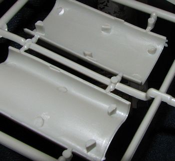
direction. The initial sprue has the intake trunking and the
vertical/horizontal stabs that can be done. The first thing I did was to
remove all the ejector towers from the first section of the intake. These
will be quite visible and so it is important that they are removed and the
many indentations filled. I used sprue cutters to get rid of most of the
towers and 220 grit sandpaper to smooth them down, after which, all the
indented areas got filler. The aft intake sections only had indented ejector
marks and was not filled. Once those were treated, they were painted
aluminum and assembled.
What I did was to start with the first sprue in the box. I know this is not
exactly according to the instructions, but looking them over, I saw that I
could get a bunch of subassemblies done before going back and following the
direction. The initial sprue has the intake trunking and the
vertical/horizontal stabs that can be done. The first thing I did was to
remove all the ejector towers from the first section of the intake. These
will be quite visible and so it is important that they are removed and the
many indentations filled. I used sprue cutters to get rid of most of the
towers and 220 grit sandpaper to smooth them down, after which, all the
indented areas got filler. The aft intake sections only had indented ejector
marks and was not filled. Once those were treated, they were painted
aluminum and assembled. 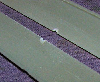 Wings and control surfaces.
I am also not a fan of the current trend to have sprue gates flush with
gluing surfaces. Not only do I tend to oversand when removing them, but if
not careful cutting them free, I'll take chunks out of the plastic. I had
this happen on the trailing edges of two of the horizontal stabilizer halves
and all eight of the aileron and flap halves. I also found two of them with
large, rather thick flash so care had to be taken when removing these items.
As I said, treat it like a short run kit. Eventually I got the divots
repaired and assembled the wing halves after filling in the inner
Wings and control surfaces.
I am also not a fan of the current trend to have sprue gates flush with
gluing surfaces. Not only do I tend to oversand when removing them, but if
not careful cutting them free, I'll take chunks out of the plastic. I had
this happen on the trailing edges of two of the horizontal stabilizer halves
and all eight of the aileron and flap halves. I also found two of them with
large, rather thick flash so care had to be taken when removing these items.
As I said, treat it like a short run kit. Eventually I got the divots
repaired and assembled the wing halves after filling in the inner
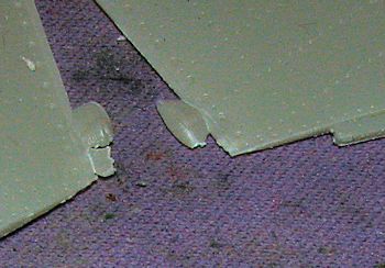 pylon holes. These items were
all set aside while I attended to other subassemblies.
pylon holes. These items were
all set aside while I attended to other subassemblies.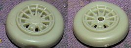 When I got around to assembling
the wheel halves, I found that for both nose wheel options, the area where
the axle fit was not open. I used a drill bit to drill this area out. I also
decided to use the later finned nose wheel as most photos I found of the
F-86D had this wheel, though not all of them so apparently the early wheels
were used until they were no longer viable. These also seem to me to be the
same nose wheels used on the F-80. I found the nose wheel assembly to seem a
bit wide as well. The main wheels are not the finned variety, but the early
'lobed' versions.
When I got around to assembling
the wheel halves, I found that for both nose wheel options, the area where
the axle fit was not open. I used a drill bit to drill this area out. I also
decided to use the later finned nose wheel as most photos I found of the
F-86D had this wheel, though not all of them so apparently the early wheels
were used until they were no longer viable. These also seem to me to be the
same nose wheels used on the F-80. I found the nose wheel assembly to seem a
bit wide as well. The main wheels are not the finned variety, but the early
'lobed' versions. 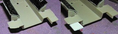 Cockpit. I then moved on to
the cockpit components. I know this is jumping around, but that is often how
I build models. First thing I noticed is that the rear of my cockpit tub was
short shot. Since it was sort of important that this not be like this, I
flattened out the area, cut a section of plastic card to fit in place, and
then attached it. While it was drying, I flooded the underside of it with
super glue as there was a rather large gap that would need to be filled in
somewhat. It is nothing fancy, but does provide the additional bit for when
the tub is installed in the fuselage.
Cockpit. I then moved on to
the cockpit components. I know this is jumping around, but that is often how
I build models. First thing I noticed is that the rear of my cockpit tub was
short shot. Since it was sort of important that this not be like this, I
flattened out the area, cut a section of plastic card to fit in place, and
then attached it. While it was drying, I flooded the underside of it with
super glue as there was a rather large gap that would need to be filled in
somewhat. It is nothing fancy, but does provide the additional bit for when
the tub is installed in the fuselage. 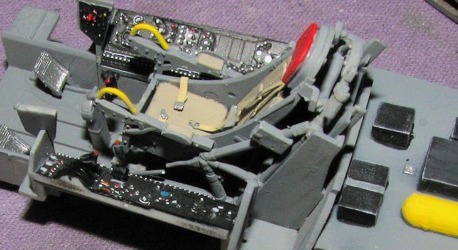 The kit provides
decals for the main side consoles and the instrument panels. These actually
fit over the raised detail, though it took several applications of a strong
setting solution to get them to do so. The end result is quite pleasing. I
then attached all the rest of the bits to the cockpit tub and painted them.
When it came time to install the seat in the cockpit, I found that when I
glued the foot rests in place, it caused the frame to be too narrow for the
openings in the floor. I suggest adding the foot rests after the seat is
installed and before you glue in the control stick.
The kit provides
decals for the main side consoles and the instrument panels. These actually
fit over the raised detail, though it took several applications of a strong
setting solution to get them to do so. The end result is quite pleasing. I
then attached all the rest of the bits to the cockpit tub and painted them.
When it came time to install the seat in the cockpit, I found that when I
glued the foot rests in place, it caused the frame to be too narrow for the
openings in the floor. I suggest adding the foot rests after the seat is
installed and before you glue in the control stick. 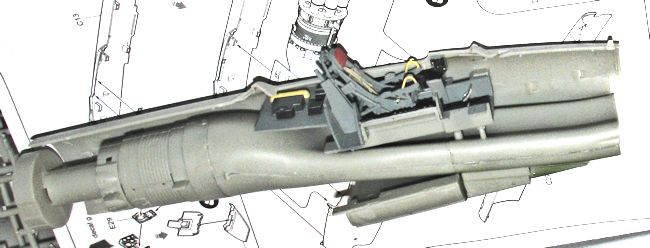 intake section is
quite small so once it is in and glued, I added some reinforcement with
super glue to hold it in place. With that done, this large assembly was
installed in one of the fuselage halves. There are tabs on the cockpit and
engine that will fit into slots in the fuselage half. I did not glue this in
as not only was the fit pretty tight, but I felt that perhaps having some
wiggle room would come in handy later. The other fuselage half was attached,
during which the three piece main instrument panel was also installed. This
installation was less than quick as the small vertical panels that one glues
on each side of the forward cockpit will make installation difficult. I
knocked these off several times before I finally got things in place. This
was followed by gluing on the two lower fuselage sections, the aft one
containing most of the main gear wells. Fit on these was fairly good though
there is a gap between the front and rear lower section that I had to take
care of.
intake section is
quite small so once it is in and glued, I added some reinforcement with
super glue to hold it in place. With that done, this large assembly was
installed in one of the fuselage halves. There are tabs on the cockpit and
engine that will fit into slots in the fuselage half. I did not glue this in
as not only was the fit pretty tight, but I felt that perhaps having some
wiggle room would come in handy later. The other fuselage half was attached,
during which the three piece main instrument panel was also installed. This
installation was less than quick as the small vertical panels that one glues
on each side of the forward cockpit will make installation difficult. I
knocked these off several times before I finally got things in place. This
was followed by gluing on the two lower fuselage sections, the aft one
containing most of the main gear wells. Fit on these was fairly good though
there is a gap between the front and rear lower section that I had to take
care of. 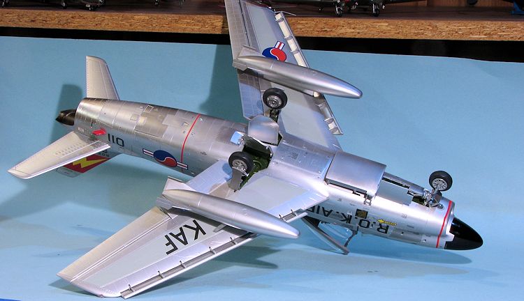 was able to get this piece to look as it should. The rear
fuselage was atrocious. The actual mating surfaces are very thin and if you
make any mistakes in fitting the intake sections (which apparently I did),
the rear will not fit all the way. Thanks to super glue and accelerator, I
was able to squeeze the rear fuselage into some semblance of how it should
fit. I found that the roughly C shaped items attached on the rear fuselage
frame prior to attaching the tail will have to be sanded down to less than
half their thickness to get any resemblance of fit.
was able to get this piece to look as it should. The rear
fuselage was atrocious. The actual mating surfaces are very thin and if you
make any mistakes in fitting the intake sections (which apparently I did),
the rear will not fit all the way. Thanks to super glue and accelerator, I
was able to squeeze the rear fuselage into some semblance of how it should
fit. I found that the roughly C shaped items attached on the rear fuselage
frame prior to attaching the tail will have to be sanded down to less than
half their thickness to get any resemblance of fit. 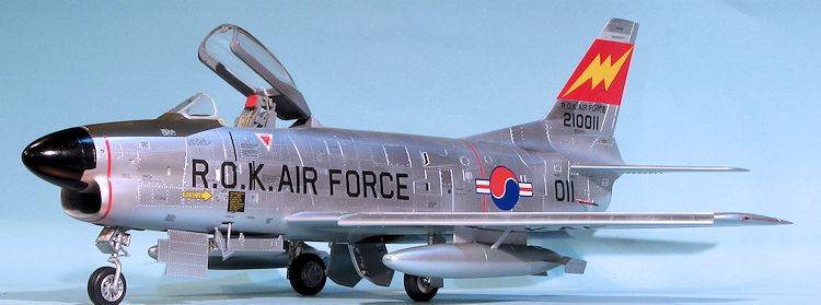 ngs in place. The
reason for this is that the slat track pieces are very easily damaged during
handling and attaching the slat makes things a lot more solid. This was
followed by the installation of the ailerons and flaps.
ngs in place. The
reason for this is that the slat track pieces are very easily damaged during
handling and attaching the slat makes things a lot more solid. This was
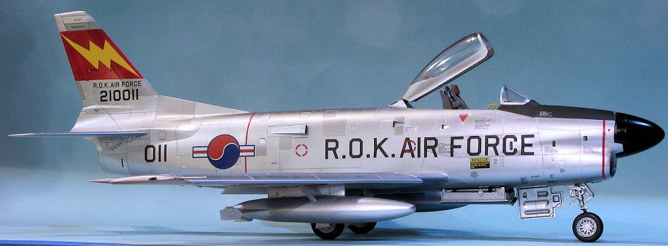
followed by the installation of the ailerons and flaps. | COLORS & MARKINGS |
 g on its tail.
 ed to the O and the . in front of it, and the A and . behind
it. The area between the legs has no carrier. This means that the marking is
easily distorted when applying it and requires a lot of fussing to get
straight. This same sort of deal applies to the R, A, F and E with the F and
E having nothing to keep their center bar from easily folding under. This
sort of thing made decal application quite a long and sometimes tedious
affair. I should mention that none of the decals are in segments so you'll
have to cut those if you want open speed brakes or those that go over the
open slats.
ed to the O and the . in front of it, and the A and . behind
it. The area between the legs has no carrier. This means that the marking is
easily distorted when applying it and requires a lot of fussing to get
straight. This same sort of deal applies to the R, A, F and E with the F and
E having nothing to keep their center bar from easily folding under. This
sort of thing made decal application quite a long and sometimes tedious
affair. I should mention that none of the decals are in segments so you'll
have to cut those if you want open speed brakes or those that go over the
open slats. | FINAL BITS |
 I then glued on the gear doors. Attach the actuators first as it will be a
lot easier. The attachment holes are too small and need to be drilled out.
The nose gear actuator was broken with most of it missing. The attachment
points for the gear doors are all butt joins so a bit difficult to keep the
doors in place while the cement sets up. The two piece forward nose gear
door took a bit of trimming and fiddling to get to fit. If you install the
nose gear retraction strut before you attach this door, it will take a bit
of ingenuity to get the hinges in place but it can be done.
I then glued on the gear doors. Attach the actuators first as it will be a
lot easier. The attachment holes are too small and need to be drilled out.
The nose gear actuator was broken with most of it missing. The attachment
points for the gear doors are all butt joins so a bit difficult to keep the
doors in place while the cement sets up. The two piece forward nose gear
door took a bit of trimming and fiddling to get to fit. If you install the
nose gear retraction strut before you attach this door, it will take a bit
of ingenuity to get the hinges in place but it can be done. | CONCLUSIONS |
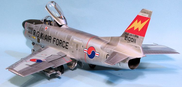
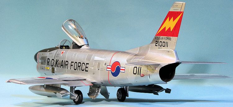
This was not a simple build. It provided some difficulties and I made some mistakes along the way. If I were to pick on anything, it would be the large sprue gates and somewhat soft plastic. I also found some of the fit to be less than sterling. It would also be nice if Kitty Hawk had done some research and provided more markings that were germane to the variant kitted. I did treat the kit like one of the short run variety and suggest to you that you do the same. It is not engineered like a Tamiya kit, but then, if Tamiy had produced it, it would have been $225 dollars or more like their Corsairs.
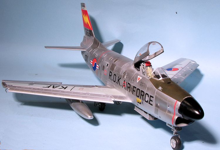
There are those who consider Kitty Hawk kits to be unbuildable and that is clearly not the case. This one took me a bit longer than I had expected, but that was pretty much due to the multiple metallics and the ton of decals that the kit provides. The end result is a quite nice model that I know some of you could build up better than I. I would build another and hope that one of their upcoming F-86Ks reaches me, now that I know some of the tricks to putting one together.
| REFERENCES |
http://en.wikipedia.org/wiki/North_American_F-86D_Sabre
The North American Sabre, by Ray Wagner, MacDonald & Co, 1963
May 2015 Thanks to Kitty Hawk Models and Glen
Coleman for the preview kit. If you would like your product reviewed fairly and fairly quickly, please contact the editor or see other details in the
Note to
Contributors.