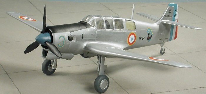
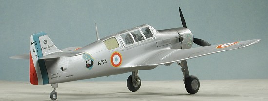
Fonderie Miniature (F.M.) 1/48 MS 472 Vanneau
|
KIT # |
6027 |
|
PRICE: |
$55.95 ($50.47 at Squadron) |
|
DECALS: |
Two aircraft |
|
REVIEWER: |
|
|
NOTES: |
Multimedia kit with resin, vac and etched bits. |
|
BACKGROUND |
|
CONSTRUCTION |
Well, as you can see, I just couldn't let the unusual pass me by, just because the kit will be a real challenge to build. While this one looks like it will be easier than the others I've done from F.M., the truth is that it really wasn't, but thanks to less photo-etched stuff, it seemed that way!
 I started off by cleaning up some of the
major components. This included removing the resin pour stub for many of
the larger parts, including the wheel well insert. Actually, I went a bit
too far on this part and sawed through a portion of the roof of the wheel
well. Once that bit was done, I glued it in place on the lower wing,
after prepping the lower wing as much as I could. It will take a healthy
dose of superglue and some clamping to get it to fit reasonably well. Once
that was done, the upper wing was glued in place and the first of several
putty/sanding sessions was done. Personally, I'm glad that the upper and
lower wings were each a separate piece as that will alleviate any dihedral
problems.
I started off by cleaning up some of the
major components. This included removing the resin pour stub for many of
the larger parts, including the wheel well insert. Actually, I went a bit
too far on this part and sawed through a portion of the roof of the wheel
well. Once that bit was done, I glued it in place on the lower wing,
after prepping the lower wing as much as I could. It will take a healthy
dose of superglue and some clamping to get it to fit reasonably well. Once
that was done, the upper wing was glued in place and the first of several
putty/sanding sessions was done. Personally, I'm glad that the upper and
lower wings were each a separate piece as that will alleviate any dihedral
problems.
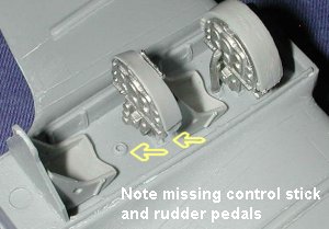
The cockpit is embedded into the upper wing section, which means that the fuselage halves will have a huge opening in the lower, forward section that fits over the cockpit. The cockpit is rather well outfitted with separate seats, instrument panel shrouds and white metal inserts for the instruments. There is also a single etched instrument panel. Why two were not provided instead of the metal bits is beyond me as they are much better detailed. I also only received a single control stick and single set of rudder pedals, though two of each are shown in the instructions. I sent several e-mails to F.M. and after a month of hearing nothing, came to the conclusion that their customer service does not exist. I eventually scrounged another control stick from the spares boxes and glued it in place.
 Next, I glued the side panels
to the inside of the fuselage, but only after scraping away at quite a bit
of the inside so there would be no clearance problems with the interior
bits. There was still a bit of a gap at the top so that was filled in and
sanded smooth. I realized that I had to install the rear windows before
gluing the fuselage halves together. The instructions do not make any
mention of these parts nor show them in the construction drawings. It is
just as well, for they are the wrong shape. They should have curved edges
and be only slightly rectangular. Instead, they have square corners and are
much more elongated. I do hope this does not portend problems with the
canopy.
Next, I glued the side panels
to the inside of the fuselage, but only after scraping away at quite a bit
of the inside so there would be no clearance problems with the interior
bits. There was still a bit of a gap at the top so that was filled in and
sanded smooth. I realized that I had to install the rear windows before
gluing the fuselage halves together. The instructions do not make any
mention of these parts nor show them in the construction drawings. It is
just as well, for they are the wrong shape. They should have curved edges
and be only slightly rectangular. Instead, they have square corners and are
much more elongated. I do hope this does not portend problems with the
canopy.
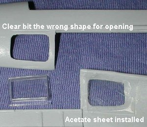 This offered
up a couple of choices. One was to cut out these curved windows and fit
them inside the framework. The lazy way out was to curve a couple of pieces
of clear acetate and superglue them to the inside of the fuselage. That is
what I chose to do. One thing I always realize when doing these kinds of
kits is that they are NOT going to be making any contests. Therefore, I can
live with a few fixes that others might not be willing to do. Once the
sheets were in and dry, the fuselage halves were glued together. I had
particular problems with the very front and ended up having to use a bit of
superglue in order for them to stay properly aligned. Once it was dry, I
test fit the fuselage over the wing. It didn't fit.
This offered
up a couple of choices. One was to cut out these curved windows and fit
them inside the framework. The lazy way out was to curve a couple of pieces
of clear acetate and superglue them to the inside of the fuselage. That is
what I chose to do. One thing I always realize when doing these kinds of
kits is that they are NOT going to be making any contests. Therefore, I can
live with a few fixes that others might not be willing to do. Once the
sheets were in and dry, the fuselage halves were glued together. I had
particular problems with the very front and ended up having to use a bit of
superglue in order for them to stay properly aligned. Once it was dry, I
test fit the fuselage over the wing. It didn't fit.
Basically, it would not fit down over the interior all the way. Several things were the cause of this. One was that the interior sidewall detail was too tall. Not much to do about that as it was firmly glued in place. The other was that the forward instrument panel housing was too tall. Trimming it wasn't an option as it would then be too short on the inside as I'd basically have to remove the rudder pedals.
What I did was to sand on the back of the forward instrument panel housing
as much as I dared without it looking too odd. Then I pressed the upper
section down as much as I could. There was still about an 1/8 inch gap.
Flooding the area with 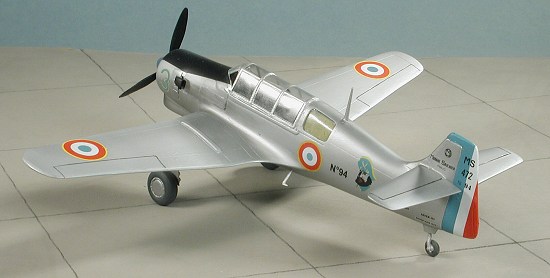 superglue was the only real way to fix things up so
that is what I did. I immediately hit it with accelerator and started
sanding. I need to mention that one has to be careful with the accelerator
as it will make the plastic where it touches rather soft and you can put
fingerprints and such in the plastic, so wash off the accelerator as soon
as the superglue has hardened. Then followed several sessions of filler and
sanding to take care of the imperfections.
superglue was the only real way to fix things up so
that is what I did. I immediately hit it with accelerator and started
sanding. I need to mention that one has to be careful with the accelerator
as it will make the plastic where it touches rather soft and you can put
fingerprints and such in the plastic, so wash off the accelerator as soon
as the superglue has hardened. Then followed several sessions of filler and
sanding to take care of the imperfections.
While all this was going on, I figured I may as well do something about the horizontal stabilizers. They were cleaned up and the mounting holes in the tail were drilled out. The fit is good on the bottom but a large gap on the top. This is because the mating surface on the stab is flat while the tail is at an angle at this area. More filler needed.
Moving to the front of the plane, I got the firewall plug ready to go. The drawing shows that a small amount of trimming is needed on the bottom as the lower fuselage isn't flat. Flat? Heck it is off at a rather large angle! A LOT of trimming is needed at the bottom. I had to rely on superglue to keep things as perpendicular at the front of this piece as I could. I finally got it in place, but it took the usual sanding and filling to take care of the gaps.
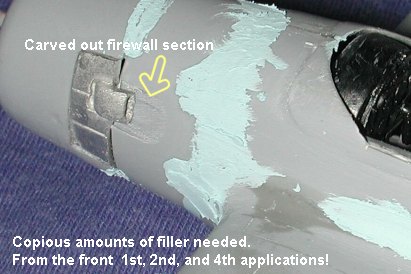 Now for the
engine cowling. There are exhaust/cowl flap assemblies that fit into the
engine cowling. These metal pieces had the flash removed with a file and
test fit. Too large. I trimmed out the cowling to get them to fit. Looks
good. Add a touch of superglue and try to fit them up against the firewall
section. Another problem. Not only are the cowl/exhaust pieces too long
fore and aft, but the entire cowl is actually smaller in diameter than the
firewall section. It doesn't help that the exhaust are built up on the
inside so trimming is out of the question. I removed the cowl bits and
deepened their mating surface on the cowling. I had no choice but to take a
square file and file down the firewall piece so that the I could fit on the
cowling and the exhaust would fit properly. It isn't prototypical at all,
but it doesn't look all that terrible. I then fit the resin engine into the
cowling (it was a tight fit getting it past the exhaust) and then glued it
and the cowling to the firewall. Again, filler is needed (see image to the
right).
Now for the
engine cowling. There are exhaust/cowl flap assemblies that fit into the
engine cowling. These metal pieces had the flash removed with a file and
test fit. Too large. I trimmed out the cowling to get them to fit. Looks
good. Add a touch of superglue and try to fit them up against the firewall
section. Another problem. Not only are the cowl/exhaust pieces too long
fore and aft, but the entire cowl is actually smaller in diameter than the
firewall section. It doesn't help that the exhaust are built up on the
inside so trimming is out of the question. I removed the cowl bits and
deepened their mating surface on the cowling. I had no choice but to take a
square file and file down the firewall piece so that the I could fit on the
cowling and the exhaust would fit properly. It isn't prototypical at all,
but it doesn't look all that terrible. I then fit the resin engine into the
cowling (it was a tight fit getting it past the exhaust) and then glued it
and the cowling to the firewall. Again, filler is needed (see image to the
right).
After a few more filler applications and having a smoother surface to work with, I turned my attention to the lower cowling. There is a rather large coolant intake that goes on the bottom. There is a small metal 'radiator' that goes inside this. At least it fits, though the instructions make no mention of this part whatsoever. There is even a small indent in the underside of the cowling for this part. Fit is fairly good and it does prevent the 'see through' effect. Fit of the intake itself is as to be expected and after some dry fitting it was glued in place and the requisite filler applied to the seams.
While that was
drying, I removed the prop and two parts of the spinner. After the usual
cleanup, I glued these items together. The fit is surprisingly good as
things go. The spinner surface was particularly rough and needed some extra
sanding. It also isn't exactly the shape of the one on the box art, but
what else is new. I should also mention that you are given two props, each
a bit different from the other, but no indication of which one to use with
this version.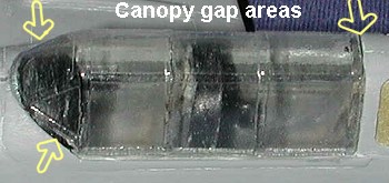
My
attention then turned to the canopy. Two are provided and these are well
done with crisp delineations of the framework. They are also rather easy to
remove from the backing with nice ridges at the back to help guide the
scribe. However, as I've come to expect, it didn't exactly fit. For one
thing, it is too short leaving a rather large gap in the back. For another,
the front section isn't exactly the same shape as the plastic to which it
has to fit. Now one can put the canopy in the middle, as shown in the
photo, to try to lessen the gaps, but a f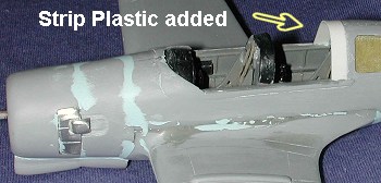 ix
is still needed.
ix
is still needed.
What I did to fix things was first to get a piece of styrene strip and curve it over the back section of the cockpit. Now I used a rather large piece that was overkill, but it did give me a lot to work with and was easy to trim down to a more manageable level. This allowed me to move the canopy forward and make the gaps in the front that much smaller and easier to fill with superglue.
After the usual coatings of filler and sanding to smooth out the area around the canopy, I continued with the kit. Next step was attaching the landing gear. The tail wheel assembly was cleaned up, glued in place and the inevitable gap filled and sanded. The main gear are not at all like what is shown in the instructions. The instructions would have you believe that there is a main gear leg, a retraction strut and a separate oleo scissors. In fact, these are all in one part. The oleos were completely filled with metal and had to be drilled and scraped out. The retraction struts are quite thick and on one of the legs, is not at the proper angle. Bending it didn't really help due to its thickness. The main gear did eventually fit into the slots in the wheel well after some trimming and were superglued in place.
 I next added some small reinforcements to the side of the fuselage aft of
the exhaust. These are supplied in the kit but are way too thick and were
replaced by small lengths of Evergreen strip plastic. There are some
additional exhaust housings that are to be fitted aft of the exhaust, but
there is no way these will fit properly due to their thickness and the fact
that the area behind the stacks had to be carved out. They were left off.
Returning to the landing gear, the gear doors were cut from the sprues.
They are too long as they are so the upper ends were thinned down and
inserted between the strut and the lower wing. Next I drilled a hole in the
upper fuselage for the radio mast. There are two holes to be drilled for
the foot steps, but since only one is provided in the kit, I chose the left
side to install it. Quite a few small pieces are left over and it seems as
if some are supposed to be used on this version, according to the box art.
However, I left them all off as I was starting to get a bit fed up with how
things were going and was anxious to complete this one.
I next added some small reinforcements to the side of the fuselage aft of
the exhaust. These are supplied in the kit but are way too thick and were
replaced by small lengths of Evergreen strip plastic. There are some
additional exhaust housings that are to be fitted aft of the exhaust, but
there is no way these will fit properly due to their thickness and the fact
that the area behind the stacks had to be carved out. They were left off.
Returning to the landing gear, the gear doors were cut from the sprues.
They are too long as they are so the upper ends were thinned down and
inserted between the strut and the lower wing. Next I drilled a hole in the
upper fuselage for the radio mast. There are two holes to be drilled for
the foot steps, but since only one is provided in the kit, I chose the left
side to install it. Quite a few small pieces are left over and it seems as
if some are supposed to be used on this version, according to the box art.
However, I left them all off as I was starting to get a bit fed up with how
things were going and was anxious to complete this one.
|
CAMOUFLAGE & MARKINGS |
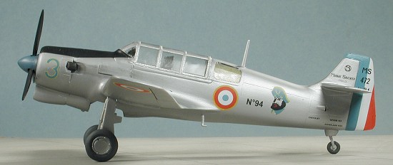
It is difficult to tell if the plane is overall natural metal or if it is painted aluminum. Aircraft for this era were painted aluminum quite often so that is how I did mine. (I'm sure I'll get e-mails telling me I did it wrong). Now I know I'll hear a gasp or two from the audience, but I did not primer this model at all. I simply started spraying on light coats of Alclad II aluminum. For one thing, it gave it a rather dull appearance, which is what painted aluminum looks like anyway. After five or six thin coats, even the filler areas disappeared without any problems.
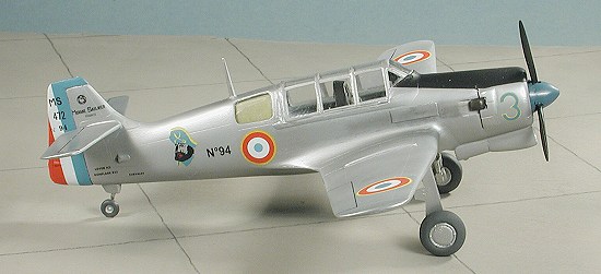 Once the aircraft was completely painted, I masked off the anti-glare panel
on the nose and painted that area flat black. Then it was time for the
decals. I started with the rudder stripes. These decals (and the rest, as I
found out) are too large for the area to be covered. They do go one well
and react favorably to Solvaset. Some careful trimming is needed on these
to keep the color overlapping to a minimum. While they fit well, they are a
bit transparent so underside colors will show through.
Once the aircraft was completely painted, I masked off the anti-glare panel
on the nose and painted that area flat black. Then it was time for the
decals. I started with the rudder stripes. These decals (and the rest, as I
found out) are too large for the area to be covered. They do go one well
and react favorably to Solvaset. Some careful trimming is needed on these
to keep the color overlapping to a minimum. While they fit well, they are a
bit transparent so underside colors will show through.
An extra sheet with five (!?) roundels is provided. The two on the main sheet are too large to fit anywhere and while the other five are still too big, they aren't as bad. I used four of these on the wings. For the fuselage roundels I had to resort to a Carpena 1/72 French insignia sheet I have. I used two of the larger ones. The rest of the decals went on without too much fuss and took rather well to some handling. After the decals were on and dry, I outlined the control surfaces with a drafting pen and applied some pastels for exhaust stains. Then I sprayed a semi-matte clear to dull the aluminum a bit more and seal in the decals.
|
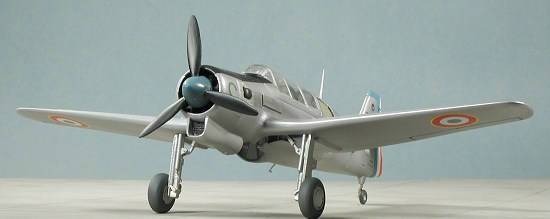
FINAL CONSTRUCTION |
Final construction consisted of gluing on the wheels, putting on the prop (after drilling out the shaft hole), and removing the masking tape. When I came to remove the tape from the rear-most windows, I was rudely surprised by realizing I'd forgotten to take off the tape I placed in there to protect the inside of the transparencies when I spray-painted the interior. Well there is nothing I can do about it as the fuselage and canopy are very securely attached. I'll just say they are sun curtains and that is that. A bit of touch-up painting of the exhausts and tail wheel and the kit was done.
|
CONCLUSIONS |
As with all FM kits I've built, I was very glad to have it finished.
Every kit I've built of theirs has required problem solving at nearly every
construction step. What makes it even more of a challenge is that often the
parts do not look like what is in the
 instructions or box art
(such as the prop spinner or the clear bits for the rear windows). However,
I'll have to say that these kits are becoming easier for me and I do enjoy
(for the most part) overcoming the problems that the kit has. It gives one
a much greater sense of satisfaction to complete a kit of this type than a
'shake and bake' Tamiya.
instructions or box art
(such as the prop spinner or the clear bits for the rear windows). However,
I'll have to say that these kits are becoming easier for me and I do enjoy
(for the most part) overcoming the problems that the kit has. It gives one
a much greater sense of satisfaction to complete a kit of this type than a
'shake and bake' Tamiya.
Will I continue to gripe about poor fit, missing parts, and vague instructions? Yes I will. Will I continue to build kits like this? Yes I will. I want modelers to know that these kits are not impossible to build. Modelers do need to have a greater level of skill and dedication than most prior to tackling kits such as this. If you are ready for a challenge and want to have something that 10,000 other modelers will NOT have on their shelves, then this is the kit for you.
BTW, just how many of you out there have actually competed an FM kit?
August 2003
#1279 in a series
Copyright ModelingMadness.com. All rights reserved. No reproduction in part or whole without express permission from the editor.
If you would like your product reviewed fairly and fairly quickly, please contact the editor or see other details in the Note to Contributors.