| KIT #: | FR 8001 |
| PRICE: | $ |
| DECALS: | Five options |
| REVIEWER: | Scott Van Aken |
| NOTES: | New tool kit |
| HISTORY |
The IAR 80 was a Romanian World War II low-wing, monoplane, all-metal monocoque fighter and ground-attack aircraft. When it first flew, in 1939, it was comparable to contemporary designs such as the German Messerschmitt Bf 109B, the British Hawker Hurricane Mk.I, and the American Curtiss P-40B/Tomahawk Mk.I and superior to the Dutch Fokker D.XXI and Polish PZL P.24. However, production problems and lack of available armament delayed entry of the IAR 80 into service until 1941. It remained in front-line use until 1944.
Built in several variants, the final stage in the IAR.80/81's wartime history was the 81C. This version changed the guns once again, this time to the Mauser MG 151/20 which was replacing the MG FF/M in German service and had just been released for Romanian use. The order for the 81C was placed in May 1942, predating the second order of the 81As.
The first order for 100 airframes was delivered, like all of the prior updates to the 81 series, with the centerline bomb rack removed to be used as fighters. An additional order for 35 was placed in February 1943, and then another 15 in January 1944. These aircraft were primarily to replace losses in earlier models, while production of the Bf 109G ramped up.
 On 10 June 1944, IAR 80s took part in a major air battle
when the USAAF attacked Ploieşti with 36 P-38 Lightnings of the 82nd Fighter
Group carrying one bomb each, escorted by 39 Lightnings of the 1st and 82 FGs.
The IAR 81Cs from Grupul
6, as well as the German fighters from I./JG 53 and 2./JG 77, intercepted the
large American formation. Romanian pilot Dan Vizanty, commander of
Grupul 6, recalled later:
On 10 June 1944, IAR 80s took part in a major air battle
when the USAAF attacked Ploieşti with 36 P-38 Lightnings of the 82nd Fighter
Group carrying one bomb each, escorted by 39 Lightnings of the 1st and 82 FGs.
The IAR 81Cs from Grupul
6, as well as the German fighters from I./JG 53 and 2./JG 77, intercepted the
large American formation. Romanian pilot Dan Vizanty, commander of
Grupul 6, recalled later:
"Our Lightning attack came as a complete surprise to the Americans. Our attack was so quick that not one of the 100 (sic) American aircraft managed to fire a single shot at our aircraft parked on the ground. Everything happened between ground level and about 2,000 meters (6,600 feet), and was total confusion. I was excited and proud of my "mills", the IAR 80s, which, thanks to their extraordinary agility, remained victorious in the air. I saw their crazy dives, quick rolls, reverse turns and inverted flying, always with just brief burst of fire to save ammunition. It was an incredible sight, but also a drama for the Lightning pilots, who, at this low altitude, were inferior to the ever-present, nimble IAR 80s".
The USAAF lost 22 or 23 P-38s on that day. Eight were claimed by Grupul for themselves – the rest were claimed by the Luftwaffe and by anti-aircraft fire. The Americans claimed 23 victories, although the Romanians and Germans each reported only one aircraft lost on that day.
The American account of this battle conflicts significantly with the Romanian one. Fighter pilot Herbert "Stub" Hatch, who took part in the dogfight, wrote that his flight of 16 P-38s, the 71st Fighter Squadron, was challenged by a large formation of Romanian IAR 81C fighters that he misidentified as Focke-Wulf Fw 190s. According to Hatch, the fight took place at and below 300 feet (100 m) in a narrow valley. Hatch saw two IAR 81Cs hit the ground after taking fire from his guns, and his fellow pilots confirmed three more kills from his guns, making Hatch an ace in a day. However, the outnumbered 71st Fighter Squadron lost nine aircraft. The Americans never again repeated the P-38 dive-bombing mission profile over Romania.
| THE KIT |
 This
is Frrom's first venture into 1/32 scale and they picked a perfect example in
the IAR-81C. For those unaware, Frrom tends to concentrate on Romanian subjects
with help from Azur in developing the kits. I have been awaiting this one since
I was first told about it earlier this year.
This
is Frrom's first venture into 1/32 scale and they picked a perfect example in
the IAR-81C. For those unaware, Frrom tends to concentrate on Romanian subjects
with help from Azur in developing the kits. I have been awaiting this one since
I was first told about it earlier this year.
Molded as you would expect a kit from the CMK family of short run kits, the detailing on this one is superb. Finely engraved panel lines that are not too deep and are quite crisply done. I did find a touch of flash and a couple of the thicker parts had sink areas that will need to be filled. There are also some ejector towers that you will need to remove before construction. These are on the larger pieces. The kit comes of five grey plastic sprues with a clear sprue for the canopy, windscreen, wing tip lights, and reflector glass. None of the part numbers are printed on the sprues so one will be continually referring to the sprue diagrams when building the kit. Resin is used for the exhaust, gun sight and the carb intake, offering a standard and filtered piece.
 A nice photo
etch fret is also provided containing a seat harness, canopy grab handle,
elevator trim tab control hinges, rudder foot straps, and cowl flaps. Frrom
could have done a much more extensive set, but decided to do a lot of the very
small pieces using injected plastic instead and I am pleased at their choice of
material as I'm sure many other modelers will be. This does bring up a down side
in that I found several thin pieces already broken on the sprues. The location
of the sprue attachment points on these thin pieces means that even more could be
broken simply removing them. It is rather standard stuff for kits of this nature
and why they are recommended for experienced modelers.
A nice photo
etch fret is also provided containing a seat harness, canopy grab handle,
elevator trim tab control hinges, rudder foot straps, and cowl flaps. Frrom
could have done a much more extensive set, but decided to do a lot of the very
small pieces using injected plastic instead and I am pleased at their choice of
material as I'm sure many other modelers will be. This does bring up a down side
in that I found several thin pieces already broken on the sprues. The location
of the sprue attachment points on these thin pieces means that even more could be
broken simply removing them. It is rather standard stuff for kits of this nature
and why they are recommended for experienced modelers.
With such a large scale to work with, one will not be surprised that there is a ton of detail. The cockpit has a lot of this with the various framework pieces, a very well done seat, floor, armor plating, trim wheels and instrument panels. Decals are provided for instruments. There is also quite a bit of sidewall detail with various control levers and knobs. I found it interesting that the interior color for this aircraft is a light blue grey rather than some sort of greenish shade. This color is also used in wheel wells and inside of gear doors.
Speaking of gear doors, each one is separate and has separate pieces that are used to attach them to the gear struts. The gear themselves are superbly molded with separate oleo scissor sections and a nicely done retraction strut. The tail gear is a skid type.
Wings are a single lower pieces to set the proper dihedral with separate upper halves. All the control surfaces are separate. The ailerons have separate hinges and the flaps can be displayed lowered if one wishes. Looking at a lot of period photos, there was not 'standard' position for the flaps as I found images of them parked with them both up and down. Elevators and rudder are also separate.
The kit has a superbly done engine that is a model in its own right. There are separate pushrods as well as a very complex engine intake and exhaust piping arrangement. You'll be spending quite a bit of time on this part of the build and it is a shame to have to hide much of it in the cowling. The cowling itself is two halves with a single forward section so no worries on seams. The cowling has separate cowl flaps and the instructions show exactly where these fit.
 An optional bomb rack is included if you should so desire.
Also separate is the windscreen and canopy which most will want to pose open to
show off the interior detail. The prop has separate blades that are keyed.
An optional bomb rack is included if you should so desire.
Also separate is the windscreen and canopy which most will want to pose open to
show off the interior detail. The prop has separate blades that are keyed.
Instructions are a bit on the busy side with well drawn construction steps and for the first time, there is color on every page of the instruction booklet. Paint references are Gunze with generic, RLM and FS 595 references given where appropriate. Five markings options are provided, all of which are Olive Green and Light Blue-Grey. Most have yellow cowlings, fuselage bands and lower wing tips. The first three options are with Escadrilla 61 or 62, Grupul 6 during 1944. The fourth is a pro-Allies plane with white fuselage band, white upper and lower wing tips and a bare metal forward cowling. The fifth is from Escadrilla 67, Grupul 2 with Eastern Front markings but only the lower cowling in yellow. This one also has a white spiral on the back spinner (or perhaps the other way around!). The decals are superbly printed by Aviprint. Separate blue triangle formation markings are provided as it is difficult to tell from photos if the were red or not. Several of the options have either plane names or unit badges.
| CONSTRUCTION |
Construction starts with the interior. As luck would have it, the very first assembly step requires three parts that were broken. The two shown in the image above, and a V shaped piece that was broken in three places and loose in the bag. I found two of the pieces and glued them together, but the third was too small and gone so I stretched some sprue to repair it. Meanwhile, I slowly started building up other pieces of the interior. I broke the floor plate piece in half removing it from the sprue. This piece has some levers that attach. There is a cutout for one of them that is smaller than the part which fits into it. This overall piece also attaches to the seat by a single thin butt join and to the instrument panel piece by the control stick linkage, making for a very flimsy construct.
I should add that since none of the parts are numbered on the sprue, a wise
builder will scan and print out a copy of the parts g uide or he will be
constantly flipping back and forth in the instructions looking for where parts
are located. As I usually bounce around building a kit like this, while fiddling
with the interior, I worked on some other bits. This includes cementing the
wings together along with all the flight control surfaces. All of these parts
had a slight seam on the trailing edges that needs to be filled and sanded down.
uide or he will be
constantly flipping back and forth in the instructions looking for where parts
are located. As I usually bounce around building a kit like this, while fiddling
with the interior, I worked on some other bits. This includes cementing the
wings together along with all the flight control surfaces. All of these parts
had a slight seam on the trailing edges that needs to be filled and sanded down.
Once that was done, I decided to install the flaps. There are two sets of flap guides; one for up and the other for down. The instruction show you attaching these to the flaps first (well, actually they don't, but that is implied), but I decided to glue them to the flap well first. A couple of the openings for these parts were heavily flashed over so I had to cut them open first. Would have been easier prior to gluing the wing halves so keep this in mind. Also the flap hinges are not all in a row on the sprue so don't go blithely expecting part 48 to be next to part 49 as it isn't (even though it is a flap hinge, but not the right one). I also assembled the ailerons and then glued on the aileron hinge sections. When dry, the ailerons were glued in place. Fit on these items was not the best and I needed to do some trimming to get things to line up properly.
When I started on the engine, I realized that not much will actually be see once the cowling is on it. I could have fudged it by leaving off bits, but figured that building it up would be the best way to do a proper kit review. When I first dry fit the engine halves, I found that they didn't fit all the way so the receptacle and the large tab had to be trimmed. This still left me with a bit of a gap, but the idea of cleaning up all those cylinder fins wasn't appealing so I just left it as one will not see the side of the engine. There was a bit of flash that had to be taken care of in the areas where the pushrods would fit.
 his brings me to the pushrods. Rather than have the rather large sprue
attachments on the 'back' side of these pieces (and there is a back side as
you'll see when you get ready to install them), they are on the 'front' where
they will be easily seen so cleaning up the pushrods is rather tedious to say
the least. Secondly, they seem to be a bit more oval than round, but that may be
due to having to remove the mold seam and sprue attachment point. Next, I found
that one needs to install the inner one on each row first and then, before the
inner one has set, attach the outer one. The mounting areas on the pushrod are
actually a bit too large for the area into which they have to fit so if you want
a nice, tight fit, you'll need to trim these down a touch. Eventually, all the
pushrods were installed.
his brings me to the pushrods. Rather than have the rather large sprue
attachments on the 'back' side of these pieces (and there is a back side as
you'll see when you get ready to install them), they are on the 'front' where
they will be easily seen so cleaning up the pushrods is rather tedious to say
the least. Secondly, they seem to be a bit more oval than round, but that may be
due to having to remove the mold seam and sprue attachment point. Next, I found
that one needs to install the inner one on each row first and then, before the
inner one has set, attach the outer one. The mounting areas on the pushrod are
actually a bit too large for the area into which they have to fit so if you want
a nice, tight fit, you'll need to trim these down a touch. Eventually, all the
pushrods were installed.
 I next went to install the exhaust and intake bits on the back. Half of these
parts attach to part F18 and the straight one attach to the resin exhaust bits.
Now, the instructions show the back of part F18 as being flat with a tab on one
side. This piece is part D 14 which they have you attach to the front of the
fuselage when you close the halves. I recommend not doing this in the earlier
steps as it will help you align the various intake tubes. I also glued part F18
to the back of the engine and then glued D14 to the back of F18 (as shown in the
image) rather than to
the forward fuselage. BTW, you'll have to enlarge the slot in the forward
fuselage half that this will eventually fit into as it is too small. Just to see
if it would fit, I test fit the engine into the taped fuselage halves. The
opening in the forward fuselage is too small so will need to be enlarged, either
with a motor tool or a piece of coarse sandpaper wrapped around a wooden dowel.
I next went to install the exhaust and intake bits on the back. Half of these
parts attach to part F18 and the straight one attach to the resin exhaust bits.
Now, the instructions show the back of part F18 as being flat with a tab on one
side. This piece is part D 14 which they have you attach to the front of the
fuselage when you close the halves. I recommend not doing this in the earlier
steps as it will help you align the various intake tubes. I also glued part F18
to the back of the engine and then glued D14 to the back of F18 (as shown in the
image) rather than to
the forward fuselage. BTW, you'll have to enlarge the slot in the forward
fuselage half that this will eventually fit into as it is too small. Just to see
if it would fit, I test fit the engine into the taped fuselage halves. The
opening in the forward fuselage is too small so will need to be enlarged, either
with a motor tool or a piece of coarse sandpaper wrapped around a wooden dowel.
 I then started gluing on the exhaust sections. Now there is no easy way to
figure out which of the two size stacks go where so what I did was remove the
resin exhaust collectors and on one, I glued on three of the stacks. I then dry
fit the engine into taped fuselage halves and saw where the one collector
was going to fit. Once that was determined, I was then able to glue the stacks
directly onto the engine. Note that there are three on the bottom that are
shaped differently and I'll probably install those just prior to permanently
gluing on the engine.
I then started gluing on the exhaust sections. Now there is no easy way to
figure out which of the two size stacks go where so what I did was remove the
resin exhaust collectors and on one, I glued on three of the stacks. I then dry
fit the engine into taped fuselage halves and saw where the one collector
was going to fit. Once that was determined, I was then able to glue the stacks
directly onto the engine. Note that there are three on the bottom that are
shaped differently and I'll probably install those just prior to permanently
gluing on the engine.
 Just to check, I cut the
cowling halves from the sprues and taped one side. I then fit the engine into
the cowlings and was not surprised when I discovered that the halves did not
close. Not even close. Shimming is not the answer to this one or the forward
cowling piece will not fit. The only fix to this is to sand down the outer
circumference of the engine. Since it is all trapped in the cowling, the cut off
rocker heads will not be visible. Another fit issue I had was with the engine
ignition ring. There seems to be no positive locator for this part. One simply
drops it in place over the gearbox housing, puts glue under it and centers it
best one can.
Just to check, I cut the
cowling halves from the sprues and taped one side. I then fit the engine into
the cowlings and was not surprised when I discovered that the halves did not
close. Not even close. Shimming is not the answer to this one or the forward
cowling piece will not fit. The only fix to this is to sand down the outer
circumference of the engine. Since it is all trapped in the cowling, the cut off
rocker heads will not be visible. Another fit issue I had was with the engine
ignition ring. There seems to be no positive locator for this part. One simply
drops it in place over the gearbox housing, puts glue under it and centers it
best one can.
 Eventually I
got the engine assembled and
after giving it a wash using AK Interactive's engine wash, set it aside.
Eventually I
got the engine assembled and
after giving it a wash using AK Interactive's engine wash, set it aside.
Back at the interior, I was slowly plugging away at it. Figuring out where
all the parts fit was rather difficult. Many of the location arrows are vague
and while later in the i nstructions there is an image of the completed interior
from the left side, there is not one for the right, meaning that fitting bits on
that side are a best guess sort of thing. What I ended up doing was that once
the seat assembly was done, I glue it to the piece that was the forward bulkhead
and the upper opening, fitting these into one fuselage half to make sure it was
properly aligned while drying. I've
nstructions there is an image of the completed interior
from the left side, there is not one for the right, meaning that fitting bits on
that side are a best guess sort of thing. What I ended up doing was that once
the seat assembly was done, I glue it to the piece that was the forward bulkhead
and the upper opening, fitting these into one fuselage half to make sure it was
properly aligned while drying. I've
 included a photo of this stage
of the build before all the bits are in place. As you can see, I've painted many
of the interior bits the shade provided in the instructions, which is RLM 76.
included a photo of this stage
of the build before all the bits are in place. As you can see, I've painted many
of the interior bits the shade provided in the instructions, which is RLM 76.
The interior side bits were glued in place. There are two pieces with control rods. The inner one was broken on the sprues and how it exactly fit is not well understood as the completed installation doesn't look like what is in the instructions. I can only assume I glued the broken parts together wrong.
After assembling the rudder pedal assembly, attaching that and attaching the control stick (the mounting hole had to be enlarged), the interior floor was finally glued on. I glued on the floor to where the tabs on the underside of the floor section butt up against the lower rod on the instrument panel section. I then glued one side to the fuselage interior and when dry, glued the other fuselage half. The interior attaches via the long rods you see in the interior section. These are a bit too long so a bit of trimming will held keep things properly aligned.
Moving back to the wings, I attached the aileron hinges to the rear of the wing and then the ailerons. I glued the ailerons in place and had to do some trimming to the guide openings to get these items to fit properly. I also glued the flaps in place. Moving to the back of the now sanded and filled fuselage, I started to attach the horizontal stabilizers. The openings for them are too small and need to be opened quite a bit. On one side, the opening was nearly fully closed up and that took quite a bit of extra work to open as it wasn't just thin flash, but rather thick plastic.
 I then moved back to the
wings to install the main gear legs. The mounting stubs on the legs are way
smaller than the openings in the wing as you can see by the photo. I
really had to grind open the holes just to get the legs in there. In addition,
the well at this place is pretty narrow and getting the main gear legs properly
installed is impossible without grinding away quite a bit of the lower landing
gear let. If you don't have a low speed motor tool, get one as it really helps
in situations like this.
I then moved back to the
wings to install the main gear legs. The mounting stubs on the legs are way
smaller than the openings in the wing as you can see by the photo. I
really had to grind open the holes just to get the legs in there. In addition,
the well at this place is pretty narrow and getting the main gear legs properly
installed is impossible without grinding away quite a bit of the lower landing
gear let. If you don't have a low speed motor tool, get one as it really helps
in situations like this.
 With those in place, I
attached the wing. Fit is fair. I had to grind down the wheel well bits a little
to get a proper fit. The rear wing/fuselage join is not the best. If one wants
to have the lower wing smoothly blend in with the rest of the lower fuselage,
you'll have a pretty good size gap on the sides
With those in place, I
attached the wing. Fit is fair. I had to grind down the wheel well bits a little
to get a proper fit. The rear wing/fuselage join is not the best. If one wants
to have the lower wing smoothly blend in with the rest of the lower fuselage,
you'll have a pretty good size gap on the sides . Now one could have this gap
closed, but there will be a step on the lower fuselage and I thought that
filling two of these gaps would be easier than fixing a step.
. Now one could have this gap
closed, but there will be a step on the lower fuselage and I thought that
filling two of these gaps would be easier than fixing a step.
With the wings on, I attached the horizontal stabilizers followed by the elevators. These have small photo etch trim tab actuator assemblies that are far too long so need to be trimmed. Naturally, after getting all four on, one of them popped off and I've not a clue where it went. I returned to the landing gear and attached the retraction strut to give it some strength. I also attached the tail gear skid assembly. After assembling the gun sight and putting that in place, I masked the canopy and windscreen. The windscreen was glued on, but the canopy seemed to be too narrow to stay in place comfortably. Even pressing it down showed that one was not going to get it to attach well in the closed position without some surgery somewhere. I filled the cockpit opening with tissue and tape and headed for the paint shop.
| COLORS & MARKINGS |
Unlike the earlier IAR-80s, these planes were in a pretty simple scheme of green uppers and light blue undersides. I first painted the lower wing tips and rear fuselage with white and then used some RLM 04 yellow. These areas were masked and the undersides were painted RLM 76. I also painted the inside and outside of the gear doors this color after assembling the small braces to the inside of them. For the upper surface, the instructions recommended RLM 83 so I used some Agama RLM 83 enamels for this. The RLM 83 took an age to dry, generally four to five days before it was no longer tacky to the touch. Eventually, it was all painted and so I gave the airframe a coating of clear gloss acrylic in preparation for the decals.
| FINAL CONSTRUCTION |
However, before that, there were more bits to attach. I installed the wheels along with the other half of the main gear fork. SAC has come out with metal gear since I did this that has the fork as a single piece. A much easier way to do things as you don't have to mess with the seam . I then attached the gear doors, which have no positive locators. The gear and retraction strut oleos were painted chrome silver and the oleo scissors were then glued in place. Again SAC has these as a single piece that is much easier to work with. The rear tailplane struts were painted RLM 76 and after shortening them, were attached in place.
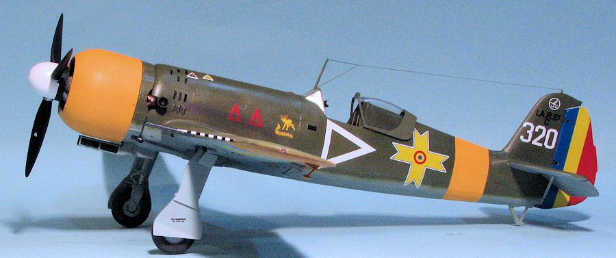
 I then started applying decals. I chose the box art
plane as I thought that was an interesting scheme. The decals are very thing and
one has to be quite careful when applying them. They need no setting solution,
but I used some Microsol anyway just to help things along. As usual, this took
me several days. The yellow in the insignia is not the same shade as the yellow
ID bands, being lighter. The airframe was then sprayed with a semi-matte clear.
I then started applying decals. I chose the box art
plane as I thought that was an interesting scheme. The decals are very thing and
one has to be quite careful when applying them. They need no setting solution,
but I used some Microsol anyway just to help things along. As usual, this took
me several days. The yellow in the insignia is not the same shade as the yellow
ID bands, being lighter. The airframe was then sprayed with a semi-matte clear.
With the decals on, I installed the shoulder belts onto the rear headrest piece and glued that into the interior opening. I had to drill out the opening in the windscreen to take the radio mast. I had chosen not to install the guns when gluing the wing halves together as I knew I'd break them off during construction. I had to open the gun holes considerably to get them to fit. I also drilled out the barrels on both the cannon and machine guns. There is no fin mast for the radio wire so I drilled a hole and installed a section of bronze wire. EZ Line was used for the radio wire.
Now back a bit to the engine. As you recall, the
cowling is too small. I had to sand away a lot of the rocker arm housings in
order to get the cowling to fit closed, and even then it was tight. I constantly
test fit the cowling front as I didn't want a horrendous mismatch. Fortunately,
that did not happen. Fitting the rest of the exhaust was a bit of a challenge. I
already had one side on so simply lined the other up to the cut outs on the
fuselage before gluing it in place. The smaller lower ones were drilled out
prior to installation and those were not an issue. Once the engine is installed
one can see almost nothing in the back of the engine anyway. The kit offers
separate cowl flaps in etched metal to provide some relief so those were glued
on.  The cowling was painted yellow as shown in the instructions. I also
assembled the prop, painting the rear portion black. The spinner itself was
painted white. Typical of much of the kit, the opening in the back of the prop
hub was too small for the protrusion on the engine so that had to be drilled
larger before fitting. The prop was glued on and after dry, the engine was
pressed onto the fuselage opening (yes, it is that tight a fit).
The cowling was painted yellow as shown in the instructions. I also
assembled the prop, painting the rear portion black. The spinner itself was
painted white. Typical of much of the kit, the opening in the back of the prop
hub was too small for the protrusion on the engine so that had to be drilled
larger before fitting. The prop was glued on and after dry, the engine was
pressed onto the fuselage opening (yes, it is that tight a fit).
Getting near the end, here. The guns were installed as were the wing tip lights. I also glued on the rudder. The last step was to paint the pitot tube white and then I used black decal stripes from the decal dungeon. The mounting hole was enlarge and it was glued in place. The masking was removed from the clear bits and the canopy section was cemented in the open position.
| CONCLUSIONS |
Typical for me, this kit took several months to complete. Partially because it is a short run kit and I had to do some additional work to get the parts to fit and partially because it takes me an age to build a 1/32 airplane kit. Now that it is done, I'm pleased with the result. This is not a kit for someone not experienced with short run kits, much of it due to the fit issues I've documented. However, one's perseverance will pay off with a superb looking model of an interesting aircraft.
| REFERENCES |
http://en.wikipedia.org/wiki/IAR-81
Septebmer 2014
Thanks to Gilles Fontaine of Frrom for the preview kit. It should be available in stores. Visit www.frrom.com for more information.
Copyright ModelingMadness.com. All rights reserved. No reproduction in part or in whole without express permission from the editor.
If you would like your product reviewed fairly and fairly quickly, please
contact the editor
or see other details in the
Note to
Contributors.
Back to the Review
Index Page 2023