
Revell 1/32 Bf-109G-6
| KIT #: | 04665 |
| PRICE: | $29.95 |
| DECALS: | Two options |
| REVIEWER: | Scott Van Aken |
| NOTES: | New tool kit with lots of inserts |
| HISTORY |
In February 1943, the G-6 was introduced on the
production line with the 13 mm (.51 in) MG 131s, replacing the smaller 7.92 mm
(.312 in) MG 17 – externally this resulted in two sizeable
Beule blisters over the gun
breeches, reducing speed by 9 km/h (6 mph). Over 12,000 examples were built well
into 1944 although contradictory factory and RLM records do not allow an exact
tally. The G-5 with a
 pressurized cockpit was identical to the G-6. A total of
475 examples were built between May 1943 and August 1944. The G-5/AS was
equipped with a DB 605AS engine for high-altitude missions. GM-1-boosted G-5 and
G-6 variants received the additional designation of "/U2". and were clearly identifyable as they use a modified, aerodynamically cleaner, engine cowl
without the usual blisters.
pressurized cockpit was identical to the G-6. A total of
475 examples were built between May 1943 and August 1944. The G-5/AS was
equipped with a DB 605AS engine for high-altitude missions. GM-1-boosted G-5 and
G-6 variants received the additional designation of "/U2". and were clearly identifyable as they use a modified, aerodynamically cleaner, engine cowl
without the usual blisters.
The G-6/U4 variant was armed with a 30 mm (1.18 in) MK 108 cannon mounted as a Motorkanone firing through the propeller hub instead of the 20 mm MG 151/20. The G-6 was very often seen during 1943 fitted with assembly sets, used to carry bombs or a drop tank, for use as a night fighter, or to increase firepower by adding rockets or extra gondola guns.
The following variants of the G-5 and G-6 were produced:
 G-6/AS (High-altitude fighter with DB 605AS engine)
One offensive weapons upgrade in 1943 for the Bf 109G was one that mounted the Army`s Werfer-Granate 21 rocket weapon system with one launching tube under each wing panel. The rockets, fitted with a massive 40,8 kg (90 lbs) warhead, were aimed via the standard Revi reflector sights, and were spin-stabilized in flight. In emergency, the tubes could be jettisoned via a small explosive charge. Intended as a "stand-off" weapon, fired from a distance of 1,200 meters and outside the effective range of the formations defensive guns, it was employed against Allied bomber formations, the Wfr. Gr. 21 rocket was unofficially known as the BR 21 (Bordrakete 21 cm) for the Bf 109G-5, G-6 and G-14. The weapons system received the designation of Rüstsatz VII on the G-10.
During the course of 1943, a number of improvements were
gradually introduced. In an attempt to increase the pilot's field of view an
armoured glass head-rest, the so-called Galland
Panzer was developed, and subsequently began
replacing the bulky armour plate in the spring of 1943. Towards the end of the
year the clear-view Erla Haube
canopy appeared, named after the Erla Maschinenwerk sub-contractor involved in
building new examples, and upgrading older examples of the Bf 109. Often
misnamed the "Galland Hood" in postwar Western aviation books and periodicals,
it eventually replaced
 the older heavily framed two-piece canopy on the Bf 109G.
The canopy structure was completely redesigned to incorporate a greater area of
clear perspex; the welded framing was reduced to a minimum and there was no
longer a fixed rear portion, with the entire structure aft of the windscreen
being hinged to swing to starboard when opened.
the older heavily framed two-piece canopy on the Bf 109G.
The canopy structure was completely redesigned to incorporate a greater area of
clear perspex; the welded framing was reduced to a minimum and there was no
longer a fixed rear portion, with the entire structure aft of the windscreen
being hinged to swing to starboard when opened.
The Bf 109 G-10, AS-engined G-5s, G-6s and G-14s as well as the K-4 saw a refinement of the engine cowlings. The Beule blisters which had formerly covered the spent shell-casing chutes of the synchronized fuselage-mount MG 131s became more streamlined and were lengthened and enlarged to cover both the weapons and the engine bearers. Initial prototype versions were symmetrical, but as larger superchargers were fitted, the engines required modified upper engine bearers to clear the supercharger housing, and as a result the final shape of the new cowling was asymmetrical, being enlarged on the port side where the supercharger was mounted on the DB engine. There were also special streamlined panels fitted to the forward fuselage. These so-called agglomerations could be seen in several different patterns. Because of their aerodynamically more efficient form in a side-view of DB 605AS and D -powered Bf 109 Gs and Ks, the agglomerations were barely discernible compared with the conspicuous fairings they replaced.
 Late-production G-6
Some versions of the G-6 and later Gs had a taller, wood-structure tail unit and redesigned rudder which improved stability at high speeds. The introduction of the WGr. 21 cm (8 in) under-wing mortar/rockets and the 30 mm (1.18 in) MK 108 cannon increased firepower. Certain production batches of the Bf 109G were fitted with aileron Flettner tabs to decrease stick forces at high speeds. A radio-navigational method, the Y-Verführung (Y-Guidance) was introduced with the FuG 16ZY.
Subsequent Bf 109G versions were essentially modified versions of the basic G-6 airframe. Early in 1944, new engines with larger superchargers for improved high-altitude performance (DB 605AS), or with MW-50 water injection for improved low/medium-altitude performance (DB 605AM), or these two features combined (DB 605ASM) were introduced into the Bf 109 G-6. Maximum speed of the G-5/G-6 was 530 km/h (320 mph) at sea level, 640 km/h (391 mph) at 6,600 m (21,650 ft)-rated altitude at 1.42 atm boost.
| THE KIT |
I am sure that by now, many of you are aware of Revell AG's new 1/32 Bf-109G. I am a fan of the type and despite having several Hasegawa kits in my stash, I picked this one up to see what it was like. Now I'm not a hard core 109 fan-boy, but I do like the type, so I've probably missed all the 'horrible inaccuracies' that would make the kit 'unbuildable'. At least that is what one often hears from 'those who know' about pretty much everything new that gets released.
First thing that struck me is that you get a lot of nicely
molded plastic for your money. The end opening
 ox is crammed full of sprues.
The next impression was that there are a lot of inserts. Don't like inserts,
well, you will not be building this kit as it is pretty obvious from looking at
the way the kit is designed that Revell AG will be doing other variants.
ox is crammed full of sprues.
The next impression was that there are a lot of inserts. Don't like inserts,
well, you will not be building this kit as it is pretty obvious from looking at
the way the kit is designed that Revell AG will be doing other variants.
Looking over the instructions I noticed that the part numbers are listed, but not the sprue on which they are attached. This will mean some hunting around for parts during construction. I then noticed errors in the first two of the 81 construction steps. Step one shows a foot plate of either part #7 or #8. Couldn't find a #7 no matter how much I looked at the sprues. Second step shows the MK.108 cannon as going on the early 109 and the 151/20 going on the late. Fortunately, though the labeling is backwards, it appears that the actual parts are correct.
As you'd expect, there is a lot of detail in the cockpit. The rear bulkhead and seat pan have belts molded in place. There are separate fuel lines and oxygen lines for the right side of the cockpit with the trim cables being separate on the left. Two different gun sights are provided depending on the variant. For the upper aft bulkhead, you get a choice of one with the bulge on it for what I think is the MW-50 system and a standard version. A wing spar attaches to the bottom of the completed cockpit assembly. Exhaust are designed to be installed from the inside, which will make painting a bit of an issue unless you want to wait until near the end to install the cowling sides.
Two different upper cowlings are provided with no indication
of which is to be used on which markings option. There are also two different
right cowling side panels depending on whether you use the MW-50 system. There
are also early/late right side gun bulges. Wheel wells are made up of separate
small straight sections to box in the well. If doing a late plane, there is a
lower wing insert for the morane
 antenna. Revell decided to incorporate the
wheel bulge into the upper wing section, but in this case it means that though
there is a single lower wing, there are two upper wing bits on each side.
antenna. Revell decided to incorporate the
wheel bulge into the upper wing section, but in this case it means that though
there is a single lower wing, there are two upper wing bits on each side.
The kit comes with two sets of elevators and tail planes but that is due to their being two of the same sprues on which one has a myriad of other bits. Now, one can do either an early rudder with the notch or the later version with the tall wooden fin. The upper portion of the fin is separate to incorporate this change. Though not shown in the instructions, there are two types of tall rudder provided and you are directed to remove the trim tabs from the one shown in the instructions. I am sure these additional rudders are for a G-10 or K. One can model the slats, flaps and radiator exhaust openings in a variety of positions. The separate elevators and ailerons also provide an ability to pose those in something other than the neutral position.
I should mention that both the main gear lets and upper tail gear are molded in left and right halves. I am sure that when Scale Aircraft Conversions offers metal gear for this kit that these items will be a single construct. These can also be put in the closed position if one wants an in flight model. There are a variety of resin pilots on the market that should fill the bill for this kit if that is your choice.
The only thing for under the fuselage is a drop tank and its rack. There are two different canopies provided; one being standard and the other the Erla Haube version. Each has its own specific head armor. Two different windscreens are provided, but no indication as to which option uses which. The difference is in the right forward side. One has a scoop and the other has a Very pistol port. The canopy sections can be posed open or closed and if closed, small tabs will need to be cut from the airframe. The prop consists of separate blades which are keyed so no worries on angle issues.
 Instructions
are typical Revell AG with only Revell paint information during the build
itself. RLM numbers are provided for the overall camouflage. Two markings
options are provided on the large swastika-free decal sheet. One is the box art
plane from Stab III./JG 5 based in Norway at the end of the war. The
instructions state a late war color scheme but only offer the usual RLM 74/75/76
scheme. This aircraft has yellow lower wing tips. The other is from April 1944
in Rumania and is an aircraft of Stab II./JG 51. It is also in RLM 74/75/76 with
yellow under the cowling, wing tips and on the fuselage band. The rudder on this
one is white. Decals look to be very well done and for those wanting something
else, there are a lot of aftermarket sheets for the big 109G and I'm sure more
are on the way.
Instructions
are typical Revell AG with only Revell paint information during the build
itself. RLM numbers are provided for the overall camouflage. Two markings
options are provided on the large swastika-free decal sheet. One is the box art
plane from Stab III./JG 5 based in Norway at the end of the war. The
instructions state a late war color scheme but only offer the usual RLM 74/75/76
scheme. This aircraft has yellow lower wing tips. The other is from April 1944
in Rumania and is an aircraft of Stab II./JG 51. It is also in RLM 74/75/76 with
yellow under the cowling, wing tips and on the fuselage band. The rudder on this
one is white. Decals look to be very well done and for those wanting something
else, there are a lot of aftermarket sheets for the big 109G and I'm sure more
are on the way.
| CONSTRUCTION |
First step was to locate a spare Hasegawa box with an actual top and bottom in which to put the sprues for this one. Naturally, the sprues were far too large for the most part, but as the build went along and the sprues were trimmed back, eventually everything fit.
Next was to determine just which version of the aircraft to build. As all the bits are there for any of a myriad of combinations, you can pick one you want. I chose a version with the standard canopy and the small tail wheel, but with the tall wooden fin/rudder.
This one was built very slowly while I awaited the SAC metal
landing gear. You see, the kit main gear is in two halves, leaving a difficult
to clean up seam and the SAC gear will be one piece. I actually followed the
instruction build scheme on this build and so it starts with the interior. I
used the early floor plate and the later cannon housing (it is the shorter of
the two). The molde d in seat detail isn't that great so many will want to use
aftermarket for this, but I used the kit version. I like that the drop tank line
is molded in clear plastic so you can have a visible viewing window. I highly
recommend installing the forward bulkhead, aft bulkhead and the two side panels
at the same time. The fuel line is a bit tricky to get into place. When dry, I
glued on the wing spar piece. I waited until cockpit installation to glue in the
back plate and I used the early version.
d in seat detail isn't that great so many will want to use
aftermarket for this, but I used the kit version. I like that the drop tank line
is molded in clear plastic so you can have a visible viewing window. I highly
recommend installing the forward bulkhead, aft bulkhead and the two side panels
at the same time. The fuel line is a bit tricky to get into place. When dry, I
glued on the wing spar piece. I waited until cockpit installation to glue in the
back plate and I used the early version.
The tail gear is next and the housing is pretty well invisible if you use the tall tail gear. Actually, the instructions screwed the pooch again in this regard, showing the late gear well plate and the early tail gear which has an oleo scissors. No way will you get the oleo to fit unless you use the early gear well plate, which is not shown. It is part #70 not #69. You can see the difference between the two in the image (small tail gear plate installed). I installed these pieces, taping the fuselage together while the well plate dried.
 Next the
exhaust were installed from the inside of the nose section. It would have been
nice were these designed to be installed from the outside to make it easier to
paint. 1/48 kits have done so and I see no reason why Revell engineers couldn't
have designed it in this manner. I then glued together the fuselage halves,
trapping the prop shaft during the process. Fit is pretty good, though it does
leave quite a few seams. I also glued on the engine upper cowling and fuselage
side panels. I chose the
'straight' gun opening upper piece and the early right side panel without the
bulge in it as I believe that was for the MW 50 injection system, which this
plane did not have. Fit there is also only fair. I had to do the 'squeeze, press
and superglue' routine to get the panels to join up without large gaps or
misalignments. On the left side there was a bit of a step between the fuselage
and the insert, which I will leave as is. I also attached the tall fin which had
gaps as well.
Next the
exhaust were installed from the inside of the nose section. It would have been
nice were these designed to be installed from the outside to make it easier to
paint. 1/48 kits have done so and I see no reason why Revell engineers couldn't
have designed it in this manner. I then glued together the fuselage halves,
trapping the prop shaft during the process. Fit is pretty good, though it does
leave quite a few seams. I also glued on the engine upper cowling and fuselage
side panels. I chose the
'straight' gun opening upper piece and the early right side panel without the
bulge in it as I believe that was for the MW 50 injection system, which this
plane did not have. Fit there is also only fair. I had to do the 'squeeze, press
and superglue' routine to get the panels to join up without large gaps or
misalignments. On the left side there was a bit of a step between the fuselage
and the insert, which I will leave as is. I also attached the tall fin which had
gaps as well.
 Once the fuselage was sanded down, lost lines were rescribed
and I moved on to installing the supercharger intake, the oil cooler and then
began on the wings. After test fitting the cooler housing I noticed that the
ends of it will butt up to the lower wing seam so I decided to leave it off
until after the lower wing section was installed. Just in case. I also installed
the gun housing bulges. These pieces have four alignment pins on them, but I
only had two holes (as you can see in the previous image). Looking at the side
panel I did not use, I noticed that there were the holes waiting to be opened
up. The instructions totally miss this minor item. Cutting off the two lower
pins will solve the issue.
Once the fuselage was sanded down, lost lines were rescribed
and I moved on to installing the supercharger intake, the oil cooler and then
began on the wings. After test fitting the cooler housing I noticed that the
ends of it will butt up to the lower wing seam so I decided to leave it off
until after the lower wing section was installed. Just in case. I also installed
the gun housing bulges. These pieces have four alignment pins on them, but I
only had two holes (as you can see in the previous image). Looking at the side
panel I did not use, I noticed that there were the holes waiting to be opened
up. The instructions totally miss this minor item. Cutting off the two lower
pins will solve the issue.
Next I started assembling the wings. Once the cooler radiators
were installed, on one side I built up the gear w ell first. On the other I did
not. The 'did not' side fits a bit better so in this case, jumping a bit ahead is
not the thing to do. Install the wing stubs, then assemble the gear well pieces
(of which there are three on each side). This is a bit fiddly, but you'll
eventually get all the bits properly aligned. I then started fitting the lower
wing sections. For the early 109G-6, you have to install the Morane antenna
mount upside down to where there is no detail. Then fill it in with your
favorite putty/filler. The lower wing is in two halves, meeting at the center.
The fit here is fairly good, though the gaps it will leave are larger than the
panel lines, a typical situation I found with this kit.
ell first. On the other I did
not. The 'did not' side fits a bit better so in this case, jumping a bit ahead is
not the thing to do. Install the wing stubs, then assemble the gear well pieces
(of which there are three on each side). This is a bit fiddly, but you'll
eventually get all the bits properly aligned. I then started fitting the lower
wing sections. For the early 109G-6, you have to install the Morane antenna
mount upside down to where there is no detail. Then fill it in with your
favorite putty/filler. The lower wing is in two halves, meeting at the center.
The fit here is fairly good, though the gaps it will leave are larger than the
panel lines, a typical situation I found with this kit.
I then installed the other wing and went to install the two center lower fuselage pieces. Having been forewarned by the gun bulges, I opened up the four holes in the large piece for the tank mount. Again, the instructions were totally devoid of information regarding the need to open these holes. I then started installing the upper outer wing sections when the lower wings were dry. I had to do some creative wing bending, using superglue and accelerator to keep the upper wing join gap from being way too large. I also glued on the forward radiator lips in a somewhat open position. Despite my efforts, there was a small step between the upper wing halves near the rear of the join. That took some more filler. On the underside, I had to use quite a bit of filler just aft of the oil cooler at the lower forward wing/fuselage join. I was glad I held off putting on the cooler cover until taking care of this.
 The rudder and tailplanes were attached next. The rudder gets
a trim tab actuating rod that effectively solidifies the rudder in the neutral
position. The oil cooler cover was installed and fit is fair, needing filler to
take care of the gaps. Somehow, during all this handling, I managed to break off
and lose one of the tabs that holds the canopy in the open position. I then
started on the radiator coolant flaps, the ailerons and the flaps themselves.
The coolant flaps and the flaps are supposed to be build to move. I had no
issues with the flaps and they worked great, but I could only get the lower
coolant flap to be movable. I ended up gluing them both into place.
The rudder and tailplanes were attached next. The rudder gets
a trim tab actuating rod that effectively solidifies the rudder in the neutral
position. The oil cooler cover was installed and fit is fair, needing filler to
take care of the gaps. Somehow, during all this handling, I managed to break off
and lose one of the tabs that holds the canopy in the open position. I then
started on the radiator coolant flaps, the ailerons and the flaps themselves.
The coolant flaps and the flaps are supposed to be build to move. I had no
issues with the flaps and they worked great, but I could only get the lower
coolant flap to be movable. I ended up gluing them both into place.
Next I attached the front and rear canopy sections. This as well as the center section were first masked then brush painted with RLM 66. Once they were in place, the opening was masked and I headed off to the paint shop.
| COLORS & MARKINGS |
 This aircraft was painted in the standard RLM 74/75/76 color
scheme so the first color to be done was RLM 76 on the underside and most of the
side of the fuselage. I used Model Master enamels for all these shades. I then
masked off the underside of the tailplanes and painted the upper surfaces with
RLM 74, the darker of the two upper surface colors. Then the kit sat for a few
weeks while I worked on other projects. Coming back to it, the RLM 75 was
applied in the non-splinter pattern.
This aircraft was painted in the standard RLM 74/75/76 color
scheme so the first color to be done was RLM 76 on the underside and most of the
side of the fuselage. I used Model Master enamels for all these shades. I then
masked off the underside of the tailplanes and painted the upper surfaces with
RLM 74, the darker of the two upper surface colors. Then the kit sat for a few
weeks while I worked on other projects. Coming back to it, the RLM 75 was
applied in the non-splinter pattern.
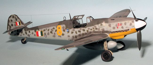
I had forgotten to paint the lower cowling yellow so painted that white and then yellow before masking after it had dried thoroughly. I then did a bit more RLM 76 painting and settled down to do the side mottling. The scheme for this aircraft was basically a bunch of dots in the two upper surface colors. Fun to paint and different from what I've done in quite a while.
| FINAL CONSTRUCTION |
 Once all the
camo was done, I went on to some of the finishing steps. I had forgotten to
attach the DF loop antenna so did that. I also painted all the prop blades with
RLM 70 and painted the spinner in black with a white segment. I am very glad
that Revell gives one an extra prop blade and the picture shows what happened
when I removed one from the sprue. These blades are very thin and rather
flexible, unlike what I've experienced in the past with big scale 109s.
Once all the
camo was done, I went on to some of the finishing steps. I had forgotten to
attach the DF loop antenna so did that. I also painted all the prop blades with
RLM 70 and painted the spinner in black with a white segment. I am very glad
that Revell gives one an extra prop blade and the picture shows what happened
when I removed one from the sprue. These blades are very thin and rather
flexible, unlike what I've experienced in the past with big scale 109s.
I then figured it was time to start on the decals so I put the kit on the kit landing gear as a temporary measure and sprayed the airframe in gloss clear. On the way back to the work bench, I was viciously attacked by felines whose sole motive was to cause me to drop the kit. This resulted in a few broken parts on the tailplane, but after bravely defending myself from the onslaught, I gathered up the broken bits and glued them in place.
Decals were next and for this aircraft I used Stormo Decals 32-003. These are very nicely printed and I chose one of the options without any of the German insignia on them. One thing I did notice is that in some instances, the decal numbers for this option did not match anything on the sheet. Also, none of the data markings shown on the instructions were on the sheet. This wasn't a major problem, but shows what happens when one takes a set of 1/48 instructions and uses them for 1/32 as well where there is often not enough room for everything provided on the smaller scale sheet. So what that meant is that all the data markings had to come from the Revell sheet. Not an issue as they are nicely done. I put on just about all the data markings, a job that took quite a while. For those wondering if the Italians would have kept all that German stenciling, I'd say yes. This was all put on at the factory and I doubt they'd take the time to change it.
 Once the decals were on, I installed the gear. For this one I
used Scale Aircraft Conversions #32078, a set that is brand new and recently
released for this kit. It has several benefits over the kit gear. One is that
each main leg is one piece rather than three pieces as provided by Revell. The
other is that you can slightly bend the metal, making it much easier to install
the tail wheel and to get the main gear properly aligned. Like the kit gear, the
main gear is a bit loose so it is advisable to use accelerator once they are
super glued into position. The main wheels were installed and they are such a
tight fit that no cement was needed. I also glued on the slats at this time.
Once the decals were on, I installed the gear. For this one I
used Scale Aircraft Conversions #32078, a set that is brand new and recently
released for this kit. It has several benefits over the kit gear. One is that
each main leg is one piece rather than three pieces as provided by Revell. The
other is that you can slightly bend the metal, making it much easier to install
the tail wheel and to get the main gear properly aligned. Like the kit gear, the
main gear is a bit loose so it is advisable to use accelerator once they are
super glued into position. The main wheels were installed and they are such a
tight fit that no cement was needed. I also glued on the slats at this time.
It seems as if the last bits always take the most time on most kits. With this one there were quite a few of these. I installed the drop tank braces and found they were too long so trimmed them before attaching the tank itself. Had I realized the overlength situation earlier, I'd have trimmed the bottom (by about 2mm or so), but instead had to trim the upper sections, not the best place. The tank was glued on and then I attached the aileron mass balances. This was followed by the gear doors and pitot tube.
The prop assembly had to be drilled out a bit to allow the
shaft to fit. I also needed to drill a hole for the radio mast. The kit was then
given a coat of semi-matte clear, where I discovered a few small areas of decal
silvering. I removed the masking from the clear bits. The main canopy had the
armor plating and the locking handle glued on. I used the later head armor as
the drawing for the decals implied that this
 was used.
Since it fit, it was no issue. Apparently this later armor section could be
retrofitted to the earlier canopy. Despite having broken off one of the canopy
mounting posts, the canopy fit well on the remaining one. I then drilled out the
antenna feed attachment at the rear of the canopy and using EZ Line, strung a
radio antenna. The wing tip lights were the last pieces to be attached and
despite having one go flying, I found it and glued them in place. These actually
fit quite well. The usual touch up painting was required followed by some pastel
exhaust stains. I'm not big on weathering or panel enhancement so none of that
was done and the model was done.
was used.
Since it fit, it was no issue. Apparently this later armor section could be
retrofitted to the earlier canopy. Despite having broken off one of the canopy
mounting posts, the canopy fit well on the remaining one. I then drilled out the
antenna feed attachment at the rear of the canopy and using EZ Line, strung a
radio antenna. The wing tip lights were the last pieces to be attached and
despite having one go flying, I found it and glued them in place. These actually
fit quite well. The usual touch up painting was required followed by some pastel
exhaust stains. I'm not big on weathering or panel enhancement so none of that
was done and the model was done.
| CONCLUSIONS |
As usual, a kit of this size and complexity was not a quick build. Though I'm sure there are folks out there who would have this done in a few weeks, it took me nearly two months. I very much liked the ability to do a wide variety of G-6 aircraft as the kit is quite complete and very detailed. It is also at a most reasonable price for a kit of this size and I'm sure RoG will sell every one it produces. This level of detail is probably it biggest fault in addition to being its biggest plus. Thanks to all the very small parts and inserts it is a rather fiddly kit to build. I'm not sure why RoG wanted operating flaps, radiator coolant doors, rudder and elevators. The rudder has to be fixed to attach the actuating rod, the coolant doors have to be fixed in place (at least I couldn't get them to be movable) and the elevators have flimsy and easily broken joints so were glued in place. Only the flaps remained movable on my model. I also found the multi-piece main gear to be a bother and that is why I used the one-piece Scale Aircraft Conversions set. I was also disappointed by the errors in the instruction sheet. You would think that RoG would have someone check over those sorts of things.
In my mind and experience, the Hasegawa 1/32 Bf-109 remains my top choice in this scale. Not to say it is the most accurate as the boffins will be quick to point out what is wrong, but it is an easier to build kit and those differences are quite small. The Hasegawa kit suffers from being expensive and not quite as detailed as the RoG kit. However, most modelers will probably want to stick with the RoG kit if for no other reason than price. It is a good kit and I'm glad it was produced. I will definitely pick up their upcoming G-10 kit with the type 110 cowling as I still have some unused decal schemes for that sub-variant.
| REFERENCES |
http://en.wikipedia.org/wiki/Messerschmitt_Bf_109_variants#G-5.2C_G-6
November 2013
Thanks to me for the review kit. Thanks to Scale Aircraft Conversions for the metal landing gear. Thanks to Stormo Decals for the decals.
If you would like your product reviewed fairly and fairly quickly, please contact the editor or see other details in the Note to Contributors.