Huma 1/72 Ju-288C
|
KIT # |
6001 |
|
PRICE: |
$32.98 |
|
DECALS: |
One aircraft |
|
REVIEW : |
|
|
NOTES: |
Sort of short run; see review |
|
BACKGROUND |
To read about what's in the box as well as a historical overview, visit the preview.
|
CONSTRUCTION |
This is the way I like to build a kit. The instructions have you
doing a number of subassemblies. Basically, they include the cockpit, the bomb
bay area, the tail gear, tail gun and barbettes. Now what just took 20 seconds
to write, actually took several hours to assemble! Huma's parts all required a
touch of cleanup after removing from the trees as they had either small amounts
of flash or an ejector pin mark. 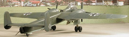 Care is needed as the plastic is softer than
what you may be used to. Fortunately, the fit is quite good. I got into the
habit of test fitting the other fuselage half after gluing in every part to make
sure I had no major fit problems before the glue had totally set.
Care is needed as the plastic is softer than
what you may be used to. Fortunately, the fit is quite good. I got into the
habit of test fitting the other fuselage half after gluing in every part to make
sure I had no major fit problems before the glue had totally set.
The biggest areas for concern are in the cockpit. Exactly where a few of these pieces fit is not unambiguous. The ones you'll have the most concern with are the small left side instrument panel (which fits on the end of the left pilot's console) and the two head armor pieces. These armor sections actually folded out of the way when not in use and attach to the side wall. There are actually a couple of interior photos included in the instructions. Though they are small, they are helpful and show a dark interior so RLM 66 is what I'll paint mine. Once all the bits and pieces were installed in the fuselage, they were painted RLM 66 or RLM 02 as needed. In the cockpit, the decals were then applied. It is a bit tough to tell which decals go where as the drawings are quite small, but it isn't impossible and was soon done.
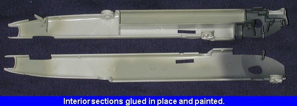
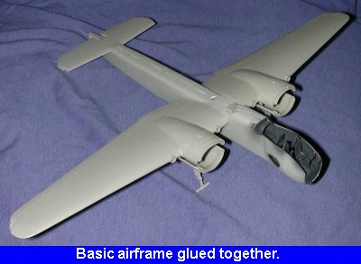
Once painted, the fuselage was glued together. One needs to take special care to keep the tail turret from being glued in place if one wants it to rotate. Needless to say, mine doesn't! At this time, the entry door was glued in the up position as there really wasn't anything inside that I wanted to display. Scratch builders will want to go nuts on the interior as there is a lot of room for detailing! Though out of print for 25 years, the reference is an excellent source of cockpit information. I found that the door didn't fit completely and there was a small gap on one side that will need to be filled.
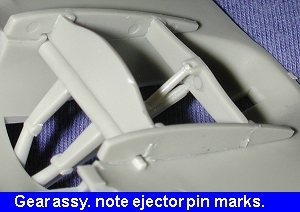 While all that was going on, I was
also working on the wings and landing gear. The landing gear is a
semi-complicated deal that has you build the wheel wells (sort of) along with
the main gear. The gear itself occupies the front of the gear bay while there
are two side pieces and a rear piece to complete the box. These components then
fit into slots on the lower wing half. It is best to do this before all the glue
has set so you can fudge things around a bit. I should also mention that there
are ejector pin detents on all the inner portions of these four parts that make
the wheel well and NONE on the outside where you won't see them. To my mind a
case of poor mold design, but there may be more to it than I know. Cleaning
these up will be time consuming.
While all that was going on, I was
also working on the wings and landing gear. The landing gear is a
semi-complicated deal that has you build the wheel wells (sort of) along with
the main gear. The gear itself occupies the front of the gear bay while there
are two side pieces and a rear piece to complete the box. These components then
fit into slots on the lower wing half. It is best to do this before all the glue
has set so you can fudge things around a bit. I should also mention that there
are ejector pin detents on all the inner portions of these four parts that make
the wheel well and NONE on the outside where you won't see them. To my mind a
case of poor mold design, but there may be more to it than I know. Cleaning
these up will be time consuming.
Then the lower portion of the
landing gear and 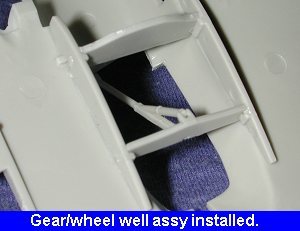 the two
retraction struts were installed. The one that leads to the top of the aft
portion of the well assembly seemed a tad short and barely reached the mounting
lugs. Once the gear is glued in place and dry, it makes for a sturdy construct.
Next, the top of the wings was installed and cleaned up. There are two intakes
on the leading edge which take what are basically nothing more than short pieces
of tubing. A bit of trimming may be needed on the holes to get them to fit
properly.
the two
retraction struts were installed. The one that leads to the top of the aft
portion of the well assembly seemed a tad short and barely reached the mounting
lugs. Once the gear is glued in place and dry, it makes for a sturdy construct.
Next, the top of the wings was installed and cleaned up. There are two intakes
on the leading edge which take what are basically nothing more than short pieces
of tubing. A bit of trimming may be needed on the holes to get them to fit
properly.
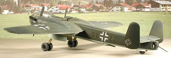
With the wings properly glued together, they were mated to the fuselage. Fit is good though I did need some filler on the join lines. The horizontal stabilizer was fitted at this time as well. The fit here is not that good. There is a rather odd gap at the back that I found quite difficult to properly smooth out. There were also some gaps at the underside that needed to be filled as well. Then the fin/rudders were glued in place. You guessed it, filler was needed at the join lines.
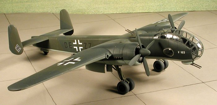
 Attention was then turned to the engines. The
exhaust stacks are molded onto a rectangular plate. These fit into slots in the
side of the engine. Fit is fairly good, but not as snug as one would wish. I
also found that on the one engine, they stuck out a bit farther forward than on
the other. To get the cowlings to fit, these had to be trimmed back slightly.
The forward cowlings are one-piece parts and fit rather well. On the same side I
had trouble with the engine exhaust pieces, they do not perfectly line up on the
top with the small fairings on the upper nacelle. It is as if the fairings are
too wide on the nacelle. On the other side the fit is perfect.
Attention was then turned to the engines. The
exhaust stacks are molded onto a rectangular plate. These fit into slots in the
side of the engine. Fit is fairly good, but not as snug as one would wish. I
also found that on the one engine, they stuck out a bit farther forward than on
the other. To get the cowlings to fit, these had to be trimmed back slightly.
The forward cowlings are one-piece parts and fit rather well. On the same side I
had trouble with the engine exhaust pieces, they do not perfectly line up on the
top with the small fairings on the upper nacelle. It is as if the fairings are
too wide on the nacelle. On the other side the fit is perfect.
 Now I had it even closer to being painted. But first the clear bits needed glued
in place. The clear parts have some distortion and are pretty badly scuffed from
being in the same bag as the rest of the kit. Future brushed on them will help
this, as will polishing, but with the stress fractures I saw, I wasn't about to
subject them to the polishing process for fear of breaking. The two side windows
that I thought would be problems were not at all. A small bead of superglue
around the openings was all that was needed to get these to fit. Same for the
upper canopy section, though I did use a touch of accelerator to speed drying as
the canopy is a touch wider than the fuselage. Fortunately, the fuselage has a
bit of play at the front so I was able to get them to match up.
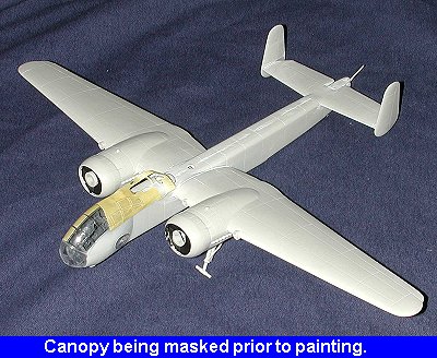
Now I had it even closer to being painted. But first the clear bits needed glued
in place. The clear parts have some distortion and are pretty badly scuffed from
being in the same bag as the rest of the kit. Future brushed on them will help
this, as will polishing, but with the stress fractures I saw, I wasn't about to
subject them to the polishing process for fear of breaking. The two side windows
that I thought would be problems were not at all. A small bead of superglue
around the openings was all that was needed to get these to fit. Same for the
upper canopy section, though I did use a touch of accelerator to speed drying as
the canopy is a touch wider than the fuselage. Fortunately, the fuselage has a
bit of play at the front so I was able to get them to match up.
With the canopy installed it was masked and then it was off to the paint shop.
|
PAINT & DECALS |
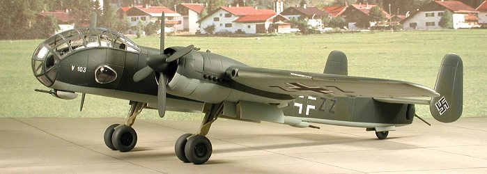
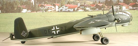
Despite the fact that the box art shows late war camo and the
color paint guide shows a light grey and dark green, RLM 70 and 71 are actually
quite close to each other in color. Often they look like the same shade if the
light isn't just right. The underside was first painted RLM 65 blue and when
dry, it was masked off . And I mean everywhere it was masked. The only way to
not get overspray where you don't want it is to cover the area. Then the upper
surfaces were painted RLM 70 and when dry, the areas I wanted to keep RLM 70
were masked. Finally, the RLM 71 was sprayed on.
It was a typical case of spending 2 hours masking and 5 minutes painting. But it is what you have to do to get the results you want. When all that was dry, the masking was removed and the kit sprayed with clear acrylic gloss where the decals were going to go.
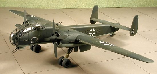
There is really no good alternative other than the kit decals. I didn't have the right font for the code letters or I'd have used another decal. The kit decals are OK, but they are thick and require industrial strength setting solution to get them to conform to panel lines. They are also not the most crisply printed ones I have ever used. I did get the tail swastikas from the spares bin as I didn't relish trimming the kit squares into one. You also only get two 'V103' decals and you need four. The kit instructions don't show you where those go, though the box top shows the two on the nose. There should also be ones on the tip of the fin. After getting all the decals on, I noticed that there is a discrepancy between the RLM 65 demarcation line on the nose shown on the box top and in the color guide. The one on the box top is correct according to photographs. Unfortunately, I followed the color guide and I'm not about to repaint that portion.
|
CONSTRUCTION CONTINUES |
With the kit painted and decaled, the next step was to add on several of the parts still in the kit box. This meant that I had to add Bare Metal foil to the main gear oleos, then glue on the oleo scissors. The wheels were then put on. The main ones fit so tightly that you may not need to glue them, though I did. Same with the tail wheel. Next the gear doors were glued in place. These are just butt joined as there are no attachment hinges on the parts.
 There are no antennas of any kind with the kit, nor is there a pitot tube
supplied though these items are shown on the box top. Well here is the deal on
these. First of all, you really need to install a pitot tube. I used a small
section of tubing and drilled a hole in the wing for it. As for the
antenna. The few photos I found of the V103 in the reference did not show much
of the upper surface of the fuselage. However one image of that plane after a
crash does show the two antenna posts and the antenna. I should point out that
this was supposed to be a retractable feature to keep it from being shot off by
the upper turret, so it is conceivable that the prototype had this feature
installed. Since this possibility exists, my lazy nature took over and I did not
add the upper antennas.
There are no antennas of any kind with the kit, nor is there a pitot tube
supplied though these items are shown on the box top. Well here is the deal on
these. First of all, you really need to install a pitot tube. I used a small
section of tubing and drilled a hole in the wing for it. As for the
antenna. The few photos I found of the V103 in the reference did not show much
of the upper surface of the fuselage. However one image of that plane after a
crash does show the two antenna posts and the antenna. I should point out that
this was supposed to be a retractable feature to keep it from being shot off by
the upper turret, so it is conceivable that the prototype had this feature
installed. Since this possibility exists, my lazy nature took over and I did not
add the upper antennas.
The last things that had to be added were the prop assemblies and the turret bits. But before this, I did touchups and any brush painting that had to be done (such as the exhausts and the drybrushing of the engine radiators). The kit was then sprayed with an overall clear matte finish. Then the masking taken off the canopy, the guns were installed in the turrets and the turret caps glued on. The props were then glued to the front of the engine radiators and the kit was finished.
|
CONCLUSIONS |
 It seems that every Huma kit gets better and better. This is by far the best
of the lot that I have built so far. Sure, it lacks in a few certain areas and
isn't as complete as one might wish, but the truth of the matter is that it is
an injected Ju-288 and the kit is really very well engineered and a fun build.
This is a kit that I could easily recommend and do so.
It seems that every Huma kit gets better and better. This is by far the best
of the lot that I have built so far. Sure, it lacks in a few certain areas and
isn't as complete as one might wish, but the truth of the matter is that it is
an injected Ju-288 and the kit is really very well engineered and a fun build.
This is a kit that I could easily recommend and do so.
|
REFERENCES |
Monogram Close-up # 2: Junkers Ju-288, by Thomas Hitchcock, 1974
November 2001
Copyright ModelingMadness.com. All rights reserved. No reproduction in part or in whole without express permission from the editor.
If you would like your product reviewed fairly and fairly quickly by a site that has thousands of visits a day, pleasecontact the editor or see other details in the Note to Contributors.