| KIT #: | KH80135 |
| PRICE: | @$57.00 SRP |
| DECALS: | Three options |
| REVIEWER: | Scott Van Aken |
| NOTES: | New tool kit |
| HISTORY |
A developed version of the original V-173 prototype, the XF5U-1 was a larger aircraft. Of all-metal construction, it was almost five times heavier, with two 1,600 hp (1,193 kW) Pratt & Whitney R-2000 radial engines. The configuration was designed to create a low aspect ratio aircraft with low takeoff and landing speeds but high top speed.
Normally, a wing with such a low aspect ratio will suffer from
very poor performance due to the degree of induced drag created at the wingtips,
as the higher pressure air below spills around the wingtip to the lower-pressure
region above. In a conventional aircraft, these wingtip vortices carry a lot of
energy with them and hence create drag. The usual approach to reducing these
vortices is to build a wing with a high
 aspect ratio, i.e. one that is long and
narrow. However, such wings compromise the maneuverability and roll rate of the
aircraft, or present a structural challenge in building them stiff enough. The
XF5U attempted to overcome the tip vortex problem using the propellers to
actively cancel the drag-causing tip vortices. The propellers are arranged to
rotate in the opposite direction to the tip vortices, with the aim of retaining
the higher-pressure air below the wing. With this source of drag eliminated, the
aircraft would fly with a much smaller wing area, and the small wing would yield
high maneuverability with greater structural strength.
aspect ratio, i.e. one that is long and
narrow. However, such wings compromise the maneuverability and roll rate of the
aircraft, or present a structural challenge in building them stiff enough. The
XF5U attempted to overcome the tip vortex problem using the propellers to
actively cancel the drag-causing tip vortices. The propellers are arranged to
rotate in the opposite direction to the tip vortices, with the aim of retaining
the higher-pressure air below the wing. With this source of drag eliminated, the
aircraft would fly with a much smaller wing area, and the small wing would yield
high maneuverability with greater structural strength.
The propellers envisioned for the completed fighter — unlike the torque-reducing counter-rotating propellers of the V-173 design — were to have a built-in cyclic movement like a helicopter's main rotor, with a very limited ability to tilt up and down to aid the aircraft in maneuvering. An ejection seat was fitted to allow the pilot to clear the massive propellers in the event of an in-flight emergency. Although the prototype was unarmed, a combination of machine guns and cannons would have been installed under the nose.
The XF5U design was promising: specifications given at the time promised great maneuverability and speeds up to 550 mph (885 km/h). However, it came at the time when the United States Navy was switching from propeller driven to jet propelled aircraft. By 1946, the XF5U-1 project was already long over its expected development time, and well over budget. With jet aircraft coming into service, the Navy finally canceled the project on 17 March 1947, and the prototype aircraft (V-173) was transferred to the Smithsonian Museum for display. Although two aircraft were constructed, a lone XF5U-1 underwent ground runs but never overcame vibration problems. Taxi trials at Vought's Connecticut factory culminated in short "hops" that were not true flights. The only completed XF5U-1 proved to be so structurally solid that it had to be destroyed with a wrecking ball.
| THE KIT |
When I heard that this kit was being
developed I was immediately interested. In past years, I had built the
rather poor fitting Hasegawa kit and really liked how it turned out. Rarely
do new kits pique my interest as things like this. It has the combination of
looking cool along with being an important development of the Vought family
of aircraft. It makes for an excellent addition to the 'what if' (whiffer)
crowd and in fact, Kitty
 Hawk has provided schemes that fill the bill quite
nicely. I should mention that there was supposed to be an anime version but
permission to use whatever the character was to be was denied very late in
production so that portion of the decal sheet was cut away, the pages
showing placement were glued shut and a black sticker put over the view on
the side of the box. However, it still shows in the parts location and those
of us who are enamoured with the subject and can make their own decals will
be able to find something suitable to put in its place.
Hawk has provided schemes that fill the bill quite
nicely. I should mention that there was supposed to be an anime version but
permission to use whatever the character was to be was denied very late in
production so that portion of the decal sheet was cut away, the pages
showing placement were glued shut and a black sticker put over the view on
the side of the box. However, it still shows in the parts location and those
of us who are enamoured with the subject and can make their own decals will
be able to find something suitable to put in its place.
The kit is molded very much like previous Kitty Hawk offerings, though inspection of the parts shows it to be blissfully free of molding glitches such as sink areas or ejector towers. The cockpit is made up of a four piece tub onto which side consoles are added along with a nice seat and there are rudder pedals that attach to the back of the instrument panel. Kitty Hawk provides decals for instruments or you can paint what is there. A small photo etch fret contains a seat harness.
One then builds up the wheel wells which contain a five piece well with the appropriate struts and linkages. Each of the four main wheels is two piece. The tail gear well is a four piece construct and this, along with the cockpit, the two main wells and a pair of engine exhaust are glued to the lower fuselage section. The upper section is then attached along with the bracing behind the cockpit.
Main gear wells have doors with separate
hinges, and the tail gear doors have small retraction struts that are
attached to them. Also on the underside are a pair of engine covers. I am
unsure why these are separate as it seems to me to have been easy enough to
mold those in place. The same applies to the upper fuselage. Fins and
rudders are separate and slot into the rear fuselage. Intakes have cooling
fans directly behind them and there is a small assemb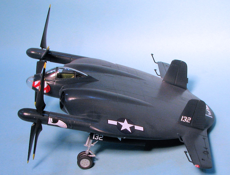 ly for the nose that
consists of a short antenna. Not sure what this is.
ly for the nose that
consists of a short antenna. Not sure what this is.
The horizontal stabilizers are in three pieces. There is a forward section that contains the formation light and mass balances. Then there is an aft section onto which one then attaches the aileron. Aileron hinges are provided. The prop hub is four pieces on either side with forward halves containing the mounts for the blades and an aft extension piece. The blades then simply slot into the forward section. These should be mounted so they turn outward. I'm not sure why they couldn't have molded the fore and aft tubes as one as the blades do not rotate, though one can position the blades any way one wants when gluing the fore and aft tubes together. This assembly then fits into appropriate areas in the fuselage. Not sure how firm the blade supports are, but I'd install the blades after attaching the mounts. On the 1/72 kit, these easily broke. The last things to attach are the unusual upper fuselage arrestor gear, which is molded in the extended position, then the canopy, which is shown only in the closed position, as well as a pair of bomb racks and bombs. The holes for these racks are pre-drilled and again, I wish Kitty Hawk would leave that option up to the builder.
The instructions are well drawn and provide logical construction steps. Color information is generic with the interior being field green and the wells and door insides being interior green. When it comes to the overall camo schemes, there is the box art plane, which is the prototype in overall sea blue with large upper fuselage walk areas. These walk areas are provided as decals. All the options have silver landing gear and wheel hubs with white tail hooks and natural wood prop blades on the outer 2/3rds of the blade with the inner section being black. When it comes to the whiffer schemes, one is overall silver with red and white rudder stripes and no upper fuselage walk areas. The really fancy whiffer option is overall sea blue with the large Uncle Sam on the upper surface with red and white stars liberally applied over the upper surface. This scheme also has red and white rudder stripes. The decals are very nicely printed and if like other Kitty Hawk decals are extremely thin, so care will be required when applying the larger markings to keep from having issues with tearing or having them fold over.
| CONSTRUCTION |
The first thing I did was look over the instructions (I know, blasphemy), and noticed that this kit is pretty much a series of subassemblies that when done, will fit either in or on the upper or lower fuselage. This fits right into my style of building so I got to work on the various subassemblies.
Initial work was to paint all the interior bits with FS 34097,
Field Green, as indicated in the instructions. I then installed the side
consoles, a big mistake if using decals. I highly recommend installing the side
console decals before installing the side consoles as they will be easier to
attach. While all that painting and decaling was going on, I built up the wheel
wells. I found that with a bit of fudging, I could fit the main
 gear into the
main wells after they were installed. I am not a huge fan of building up the
gear and wells before painting the overall model. The tail gear well was a very
tight fit and even ends up distorting the side walls a bit. You need to be sure
to remove the ejector towers or you won't get the upper fuselage to fit.
gear into the
main wells after they were installed. I am not a huge fan of building up the
gear and wells before painting the overall model. The tail gear well was a very
tight fit and even ends up distorting the side walls a bit. You need to be sure
to remove the ejector towers or you won't get the upper fuselage to fit.
I then removed the fuselage halves from the sprue as well as
the prop housings. This brings me to today's editorial; sprue attachment points.
Few people like these as they can be a pain, requiring sanding down or other
methods of erasing their existence. Kitty Hawk has become enamored with placing
the attachment points on the mating surface. This works great on canopy parts
but brings into play several problem areas when used elsewhere. One is that
often sanding away the stub will result in oversanding and a gap to fill that
wouldn't be there if the attachment was in the outside of the part. Secondly,
there seems to be little thought about where to place these as often they were
right next to an alignment pin. This often results in the loss of the pin. I
found that on the main wheels, for instance, it was very difficult to remove the sprue remnants as the gluing surface was about 1-2mm wide and butted up against
an alignment ring. Much better to have the stub on the outside of the tire.
Finally, when attached to the inside of a thin part, it is very easy to put a
chunk in the edge of this piece removing it. Now I doubt if anyone from Kitty
Hawk will read this and the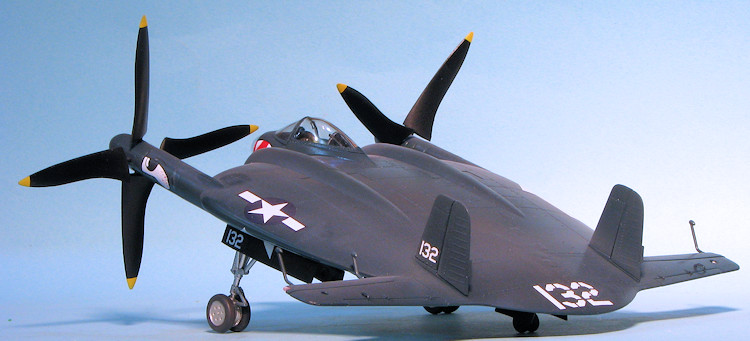 y'll go on their merry way doing what they like, but
it sure would be a step forward if the designers would think about things like
this. The folks at other model companies seem to be able to do this.
y'll go on their merry way doing what they like, but
it sure would be a step forward if the designers would think about things like
this. The folks at other model companies seem to be able to do this.
With the wells in place, I cleaned up and glued the main wheels together. I found these to be keyed to a certain extent and also for a pin receptacle to be filled with plastic. This was found in other bits through the build. When building the prop extension bits, I found the pin receptacles to be about a millimeter higher than the mating surfaces, so be sure to sand those flush so the parts will fit.
On the top and bottom of the fuselage are inserts where the engines would go. I'm not sure why these exist at all for there seems no reason for them. However, note that parts D15/17 that are shown as going on the underside are actually the upper side pieces and vice versa. I also glued together the exhaust and attached those to the inside of the lower fuselage. Note that one of the exit holes on the fuselage piece needs to be opened up a bit more to match the other side. I found small areas of flash like this throughout the build. Nothing major, but you do need to be aware of it.
I then finished up the construction of the cockpit by attaching the p.e. belts, gluing in the seat and the instrument panel. You'll need to remove the tabs from the outer portions of the panel or it won't fit in place. The instructions show this fitting to the lower fuselage. Not only is there no clear placement area, but if you do get it installed, it may not line up. It is much easier to install this into the upper fuselage half.
There is no indication of how to build this without the tail
hook assembly extended. Frankly, if one is to use the large upper surface decal,
getting it to fit over this thing would simply be a mess. Now Kitty Hawk could
have included a one-piece 'closed' option, but did not. The hook doors are super
thin and I broke
 them removing them from the sprue. They do not fit flush in the
opening so I filled these openings with silly putty so the parts would have
something to lay upon. Even then, it took several applications of filler (in
this case super glue) and sanding to get the area flush, but it looks a ton
better to my eyes. I then cemented the upper and lower fuselage halves together.
I started at the rear and worked my way forward, cutting off pins where the
receptacles were filled. I stopped at the outside of the engine openings and
went to the forward fuselage. This and the later areas inboard of the prop
shafts had super glue used to hold the parts together as the fit requires some
squeezing. In the very back, I managed to chip the fuselage removing it from the
sprue so had to use super glue again to fill that in.
them removing them from the sprue. They do not fit flush in the
opening so I filled these openings with silly putty so the parts would have
something to lay upon. Even then, it took several applications of filler (in
this case super glue) and sanding to get the area flush, but it looks a ton
better to my eyes. I then cemented the upper and lower fuselage halves together.
I started at the rear and worked my way forward, cutting off pins where the
receptacles were filled. I stopped at the outside of the engine openings and
went to the forward fuselage. This and the later areas inboard of the prop
shafts had super glue used to hold the parts together as the fit requires some
squeezing. In the very back, I managed to chip the fuselage removing it from the
sprue so had to use super glue again to fill that in.
I then started attaching the horizontal stabs and elevators. Note that parts C36/37 are shown on the wrong sides. If attached as shown, there is no hole for the elevator trim tab actuator. I left off all the clear bits and the easily broken mass balances until much later in the build. I had earlier built up and taken care of the seam filling of the prop shaft and hubs. The shaft pieces were attached, followed by the usual clean up. This was followed by the fins and rudders. The engine intake bits were assembled and installed. Note that you have to really push the center pieces down in or the lip around it will not be deep enough to allow a decent fit on the fuselage. Even then, I had to do some squeezing and super glue to get a fair fit.
| COLORS & MARKINGS |
I had already decided that this one was going to be overall gloss sea blue. This means that the wheel wells would be that color as this was pretty well the norm for this scheme until it was supplanted by the light gull grey and white scheme. However, I decided to do the landing gear legs and wheels in aluminum. Again, this was not unusual as you can find lots of photos of Panthers, Banshees and such so painted.
 The underside was painted with gloss sea blue and that
included the gear wells. I then sanded on the intake bits as the paint would
help show where I needed filler or more sanding. It took quite a bit. Meanwhile
I masked the canopy and windscreen. To get the canopy to fit fully closed, I had
to cut back about 1/2 from the front of the alignment tabs. These fit into slots
in the piece behind the canopy. I had the piece as far forward as I could get it
so I'm not sure why the fit issue. There is an armored piece to the windscreen
that the instructions miss completely. There are slots in the windscreen where
this piece fits. I painted the edges of it black. After installing the gun
sight, and repainting that area, I glued on the windscreen and the canopy.
The underside was painted with gloss sea blue and that
included the gear wells. I then sanded on the intake bits as the paint would
help show where I needed filler or more sanding. It took quite a bit. Meanwhile
I masked the canopy and windscreen. To get the canopy to fit fully closed, I had
to cut back about 1/2 from the front of the alignment tabs. These fit into slots
in the piece behind the canopy. I had the piece as far forward as I could get it
so I'm not sure why the fit issue. There is an armored piece to the windscreen
that the instructions miss completely. There are slots in the windscreen where
this piece fits. I painted the edges of it black. After installing the gun
sight, and repainting that area, I glued on the windscreen and the canopy.
I then proceded to paint the airframe as I installed pieces. This seemed to work out pretty well once I had most of the airframe painted. I also found that brush painting some of the bits worked out well and showed no difference in shade from the original Model Master enamels that I used.
| CONSTRUCTION CONTINUES |
With most of the airframe together, there were still quite a few bits to install. Included in this were the landing gear. I found that the main gear assembly to be a bit fussy. I mean, do we really need two piece oleo scissors when one casting would be a lot easier to install. During this I misinterpreted the gear door closing mechanism and installed them backwards. The legs (once you get finished fixing those you break) should be forward. It doesn't look horrible once the doors are on, but it means their attachment slots in the doors are unused. I also found the tail gear overly fussy, but did get it and the door mechanism installed. The main gear doors have separate hinges that need to be installed. Those on the inner doors are a different size from the outer doors so you have to keep that all straight.
 Building up the props was pretty
straight-forward. These are handed and as on the real plane, the blade shaft is
quite thin, so care will be needed when installing these. The prop hubs are
keyed in such a manner that you won't goof up the blade installation and are
actually quite a tight fit. I decided on doing a 'production' plane, which would
have all black props, saving me from making a mess of trying to simulate wood
prop ends.
Once the props were painted, they were carefully installed in the hubs. The fit
is so tight I did not require glue.
Building up the props was pretty
straight-forward. These are handed and as on the real plane, the blade shaft is
quite thin, so care will be needed when installing these. The prop hubs are
keyed in such a manner that you won't goof up the blade installation and are
actually quite a tight fit. I decided on doing a 'production' plane, which would
have all black props, saving me from making a mess of trying to simulate wood
prop ends.
Once the props were painted, they were carefully installed in the hubs. The fit
is so tight I did not require glue.
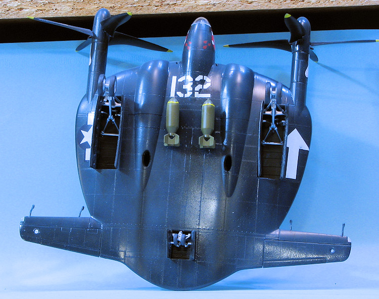
Back at the airframe, I glued on the wheels, not having much luck getting the tail wheels straight as the fit is rather loose. I also installed the mass balances, the mounting holes requiring enlarging to get them to fit. In the front I painted the nose section black and installed the small central antenna. An antenna was also glued to the underside. I did quite a bit of brush painting on the doors to cover where they had been glued in place and where I'd sanded away the sprue attachments.
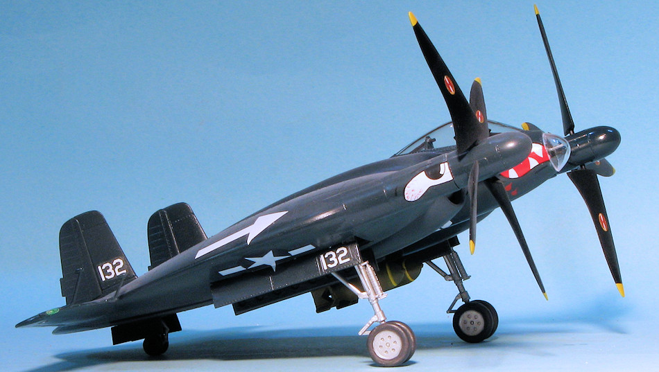
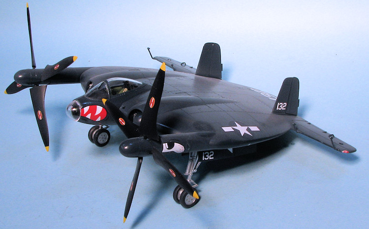
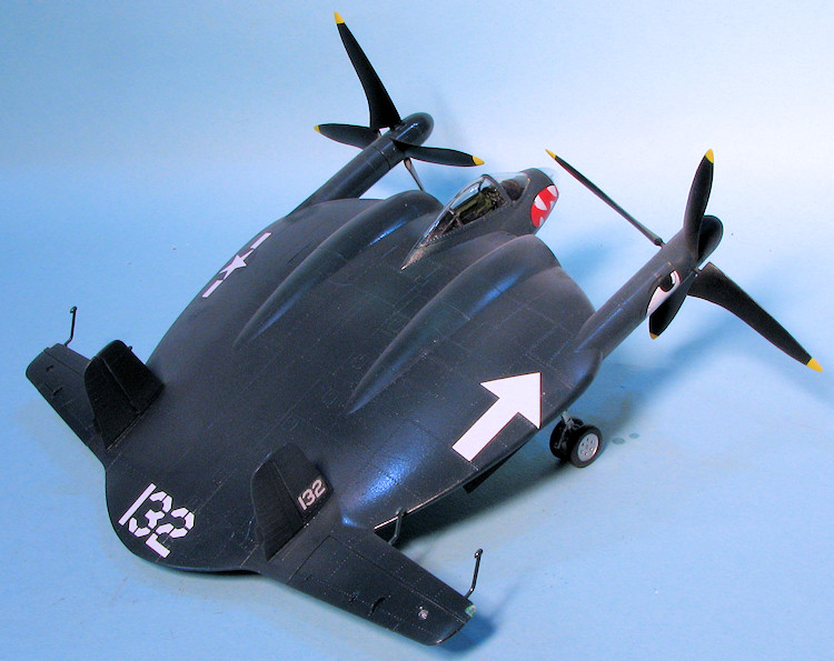
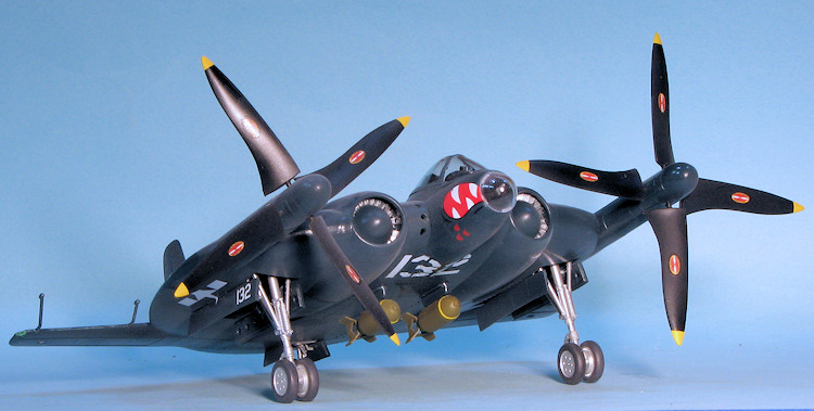
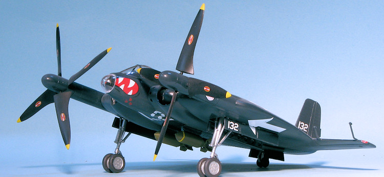
While pretty late in the game, I finally got around to the decals. To be honest, I did not what to do any of the kit markings so looked through the decal stash and came across Microscale 48-4 for the F6F. I homed in on the 'cats mouth' used by VF-27 and the arrow marking used by VF-84. Doing a bit of cutting and fiddling, I installed these along with some of the code numbers and the insignia from the kit decals to make a somewhat interesting 'WWII 1946' aircraft, despite the fact that the plane never flew. Once all the markings were on, I added the prop markings and the final bits. These were mostly clear and were the nose cap, formation lights and the landing lights on the stabs. I also glued on the bombs and the props. Note that these spin towards the middle. A bit of exhaust smoke was added and that was pretty much it.
| CONCLUSIONS |
I am pretty jazzed that Kitty Hawk decided to expend the time and effort to produce this kit in 1/48. It is not often that a model company produces a one-off and a plane that never really few. However, it makes into a pretty neat model and leaves open the fertile imaginations of modelers to come up with some rather neat 'what if' schemes.
As a late note, I was informed that I put the props on the wrong side and sure enough, I did. I'm not going to reshoot all the photos, but I did swap them around. The hubs fit so tightly that I did not have to glue them in place.
| REFERENCES |
https://en.wikipedia.org/wiki/Vought_XF5U
January 2016
Copyright ModelingMadness.com
Thanks to Kitty Hawk Models and Glen Coleman
for the preview kit. You can find this kit at your favorite hobby shop
or on-line retailer.
If you would like your product reviewed fairly and fairly quickly, please
contact the editor or see other details in the
Note to
Contributors.