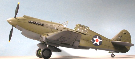
Vintage Fighter Series 1/24 P-40B/C Tomahawk
| KIT #: | VF 2402 |
| PRICE: | $119.98 (107.96 at Squadron) |
| DECALS: | Two options |
| REVIEWER: | Scott Van Aken |
| NOTES: | Includes Photo Etch and Vinyl parts |
| HISTORY |
Please visit the preview for a look at what comes in the box and a short history of the type.
| THE KIT |
It seems like kits are just getting
bigger and bigger as time goes on. Many manufacturers see this as the wave
of the future so are jumping on the bandwagon of ever larger model kits.
There are several things that have lead up to this. First is that most of
the common subjects have already been done in the smaller scales of 1/72
and 1/48, and while there are still plenty
 of subjects that could well
stand to be redone into more modern kits, there are certain aircraft that
are sure money-makers if done well. The P-51, Bf-109, Spitfire, Zero and a
few others come to mind and that includes the P-40 series. These have been
done in standard injection molding in 1/24 scale except for the P-40. Makes
it a natural for the first offering of a new company.
of subjects that could well
stand to be redone into more modern kits, there are certain aircraft that
are sure money-makers if done well. The P-51, Bf-109, Spitfire, Zero and a
few others come to mind and that includes the P-40 series. These have been
done in standard injection molding in 1/24 scale except for the P-40. Makes
it a natural for the first offering of a new company.
Secondly, there is a perception amongst some modelers that increased age means we need larger kits with larger parts. This is a fallacious reason as larger kits have MORE parts and these additional parts are small.
Finally, the market has shown that it can handle model kits that are expensive and cost over $100. I can name at least two or three dozen kits currently available that sell for these sorts of prices and sell well. So we now have a 1/24 P-40B/C to add to the list. I have to say that when it first appeared, I was pretty pleased about being able to do one as I really like the P-40 in all its guises. Yes, it wasn't a world beater, but it could hold its own and it just looked the part.
| CONSTRUCTION |
With a kit of this size it is difficult to decide where to begin. I could just follow the instructions, but instead, I started looking around for sub-assemblies. In this way, I'd have bits ready to attach when the time came. At least that is the theory!
So I started with the control
surfaces. Ailerons were pretty easy to figure out. Oddly, they are somewhat
solid on the underside; sort of as if they were metal on the bottom and
fabric on the top. Most strange. The rudder had the hinges glued
 in before
it too, was cemented together. For the elevators, I did those one at a time
so as not to get them on the wrong side. I also found that the molds were
somewhat misaligned in terms of the alignment pins. Some of the parts I cut
these off and others I just sanded the outside to match. The rudder was
particularly bad in this area and even cutting off the alignment pins
wasn't enough and I had to sand on the bottom of it to keep it from having
an angled look to it. Once one elevator was done, I trapped it between the
stabilizer and then etched 'left' and 'right' on the tabs so I wouldn't get
them backwards.
in before
it too, was cemented together. For the elevators, I did those one at a time
so as not to get them on the wrong side. I also found that the molds were
somewhat misaligned in terms of the alignment pins. Some of the parts I cut
these off and others I just sanded the outside to match. The rudder was
particularly bad in this area and even cutting off the alignment pins
wasn't enough and I had to sand on the bottom of it to keep it from having
an angled look to it. Once one elevator was done, I trapped it between the
stabilizer and then etched 'left' and 'right' on the tabs so I wouldn't get
them backwards.
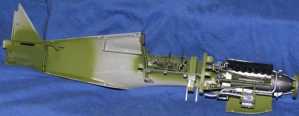
While that was going on, I started gluing parts into the cockpit. Fit is as good as you'd expect from parts this size. I also started on the engine. Now this is a bit of a quandary. The engine is well detailed for its size and while it doesn't have any wiring, it seems as if having that would be a bit of a waste as there is no way to see the sides of the engine unless you cut into the fuselage. Basically, most of us will just put in the block so that there is a place for the prop shaft and the exhaust to be attached. However, I decided to go ahead and hook up all the bits. I may not be able to see it if I glue on the upper cowling, but I thought I should at least let you see what all goes into making it. This doesn't make for a quick build as the engine contains a sizeable number of the parts on the sprues!
 Generally, the fit of the engine
parts is quite good and though the mating surfaces don't provide super
precision attachments, in many cases, they are quite tight, so having
sloppy bits isn't a problem with the majority of the joins in this kit. I
decided to assemble the block and most of the bits, choosing to paint large
assemblies (like some of the duct work and the exhaust, and the engine
mounts) separately and then join them all later. I picked on Alclad II to
do the metallics and actually brushed
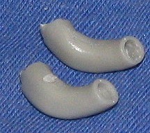
on some of the bits. Assembling all those exhaust was a bit tedious and
they really have some gaps that will need to be tackled near where they
attach to the block if you plan on showing the engine undergoing
maintenance. I also found the shallow exhaust ports to look tacky so used a
#40 drill bit to hollow them out even more (upper exhaust in image). Much
better. These were brush painted using Testors Burnt Iron. It is too bad
that they cannot be installed after the fuselage halves are put together,
but that is the way things are.
Generally, the fit of the engine
parts is quite good and though the mating surfaces don't provide super
precision attachments, in many cases, they are quite tight, so having
sloppy bits isn't a problem with the majority of the joins in this kit. I
decided to assemble the block and most of the bits, choosing to paint large
assemblies (like some of the duct work and the exhaust, and the engine
mounts) separately and then join them all later. I picked on Alclad II to
do the metallics and actually brushed
on some of the bits. Assembling all those exhaust was a bit tedious and
they really have some gaps that will need to be tackled near where they
attach to the block if you plan on showing the engine undergoing
maintenance. I also found the shallow exhaust ports to look tacky so used a
#40 drill bit to hollow them out even more (upper exhaust in image). Much
better. These were brush painted using Testors Burnt Iron. It is too bad
that they cannot be installed after the fuselage halves are put together,
but that is the way things are.
While the engine was being assembled
and painted, I turned my attention to the interior. Things here are pretty
simple as kits go. As with the engine, some of these bits are going to
disappear once the fuselage is completed. I basically glued together the
ammo bin and slotted it into the floor. The back and forward bulkheads were
glued in place. There is a little tab that is glued to the back of the rear
bulkhead to make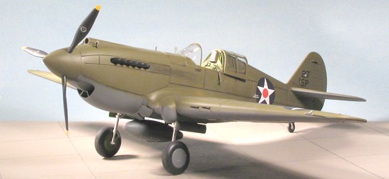 it fit more
securely when the fuselage is joined. I also glued in the flap handle and
the control stick as well as the seat attachment frame. All this stuff was
painted US Interior green. I also glued the quarter window housings and the
side panels to the fuselage sides. The side panels have other bits that
attach to them and I must say that while most bits fit OK, some parts
placement was rather vague, especially as a few of the bits didn't seem the
exact shape/size as shown in the instructions. I ran into this problem with
a few other parts of the build, most notably the bits that make up the
prop/hub assembly.
it fit more
securely when the fuselage is joined. I also glued in the flap handle and
the control stick as well as the seat attachment frame. All this stuff was
painted US Interior green. I also glued the quarter window housings and the
side panels to the fuselage sides. The side panels have other bits that
attach to them and I must say that while most bits fit OK, some parts
placement was rather vague, especially as a few of the bits didn't seem the
exact shape/size as shown in the instructions. I ran into this problem with
a few other parts of the build, most notably the bits that make up the
prop/hub assembly.
With all the bits glued in place, I also glued together the instrument panel backing and rudder pedals. This was painted Interior Green while the instrument panel face was painted black and the back of the acetate instrument panel was painted white. Be careful on this as I originally painted the wrong side white, but thanks to the miracle of acrylic white, it was really easy to remove, even when dry! I then sandwiched the instrument bits, using clear paint to attach things together. There are alignment tabs to help out. You'll probably be like me and be totally amazed at how low to the floor the instrument panel fits. It seems as if a real pilot would never be able to get his legs under it to reach the rudder pedals. I should mention that while the cockpit bits were drying, I had them trapped between the fuselage halves to be sure that the parts would fit later on.
 Meanwhile,
back at the engine, I assembled all the various bits, including the oil
cooler assembly, which takes three pieces of etched steel for the intakes,
and glued all the parts together. This was then glued onto the firewall. I
gave stuff a wash and dry-brush. A total waste of my time as it turned out,
but I did want to build all the parts as best I could. The instructions
give a reasonable set of painting instructions for the engine so it will
look really cool before it gets hidden away. This whole thing was
then glued onto the firewall/interior section.
Meanwhile,
back at the engine, I assembled all the various bits, including the oil
cooler assembly, which takes three pieces of etched steel for the intakes,
and glued all the parts together. This was then glued onto the firewall. I
gave stuff a wash and dry-brush. A total waste of my time as it turned out,
but I did want to build all the parts as best I could. The instructions
give a reasonable set of painting instructions for the engine so it will
look really cool before it gets hidden away. This whole thing was
then glued onto the firewall/interior section.
Something that this kit really should
have had included was a harness set. I don't know why this was overlooked,
because in this scale, it is such an obvious detail. Needless to say, I had
to find a set. Digging through
 the
copious aftermarket at my favorite hobby emporium, I came across a set of
Eduard pre-painted US harnesses. There are two sets in each pack; one in
OD and the other in cream. It is
a simple matter to do a bunch of bending and gluing to make a full set. I
first attached the seat belts to the kit seat. Then it was glued in place.
The shoulder harnesses were shown attached behind the seat and really, to
the rear bulkhead. I decided to thread them through the bulkhead in order
to make them easier to attach. A
the
copious aftermarket at my favorite hobby emporium, I came across a set of
Eduard pre-painted US harnesses. There are two sets in each pack; one in
OD and the other in cream. It is
a simple matter to do a bunch of bending and gluing to make a full set. I
first attached the seat belts to the kit seat. Then it was glued in place.
The shoulder harnesses were shown attached behind the seat and really, to
the rear bulkhead. I decided to thread them through the bulkhead in order
to make them easier to attach. A
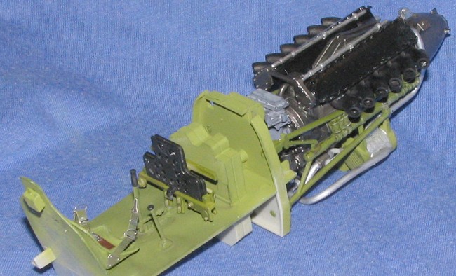 candle
and Xacto knife were all that was needed to melt some slots for these belts
as you can see in the image to the right. These shoulder straps were left
off until just before the interior was glued in place. The image to the
left shows the engine/cockpit assembly from the rear. You can see the
little tab behind the bulkhead that I mentioned several paragraphs before.
You can also see the rather beefy mounting tabs.
candle
and Xacto knife were all that was needed to melt some slots for these belts
as you can see in the image to the right. These shoulder straps were left
off until just before the interior was glued in place. The image to the
left shows the engine/cockpit assembly from the rear. You can see the
little tab behind the bulkhead that I mentioned several paragraphs before.
You can also see the rather beefy mounting tabs.
 Moving
a bit farther back on the fuselage, I glued in the tail gear attachment
section as well as the rear gear door slots and then glued on the rudder. I
screwed up the tail wheel upper mount by gluing it on the wrong side of the
bulkhead. A bit of grunting and groaning along with some additional glue
were enough to break loose the bond so I could attach it the proper way. I
almost forgot the upper rudder hinge so be sure that you get this important
part in place during the construction of the rudder or you'll have a bit of
a hassle getting things to line up.
Moving
a bit farther back on the fuselage, I glued in the tail gear attachment
section as well as the rear gear door slots and then glued on the rudder. I
screwed up the tail wheel upper mount by gluing it on the wrong side of the
bulkhead. A bit of grunting and groaning along with some additional glue
were enough to break loose the bond so I could attach it the proper way. I
almost forgot the upper rudder hinge so be sure that you get this important
part in place during the construction of the rudder or you'll have a bit of
a hassle getting things to line up.
 I
finally threaded in the shoulder harness parts, glued the cockpit/engine
assembly to the left fuselage half, and, while trapping the tail gear,
glued the fuselage halves together. I should mention at this stage that I'd
done quite a bit of prepainting on the fuselage. This is especially
important around the engine exhaust. To keep from having to mask things, I
painted all but the join areas on the fuselage with Olive Drab. This really
helped later in the build as having all that stuff prepainted cut back on a
lot of masking. I did have to clamp several areas to get things to fit
properly. There were gaps all along the fuselage seam so that had to have a
couple of coats applied later on.
I
finally threaded in the shoulder harness parts, glued the cockpit/engine
assembly to the left fuselage half, and, while trapping the tail gear,
glued the fuselage halves together. I should mention at this stage that I'd
done quite a bit of prepainting on the fuselage. This is especially
important around the engine exhaust. To keep from having to mask things, I
painted all but the join areas on the fuselage with Olive Drab. This really
helped later in the build as having all that stuff prepainted cut back on a
lot of masking. I did have to clamp several areas to get things to fit
properly. There were gaps all along the fuselage seam so that had to have a
couple of coats applied later on.
 During
all that work on the fuselage, I went to work on the wings. These gave me
only a teeny bit of trouble and that was mostly in regards to the flaps. I
basically glued everything and then did the painting before gluing the
upper and lower wing halves. The gear is designed so you can display the
kit with retractable landing gear so the hinges have to be assembled and
installed. Each of the gear wells is made up of four sections and fits
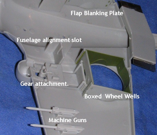
quite well. The guns must be installed at this time. Though there is no
provision to see these, some relatively complete gun shapes are provided. I
must say that these look awfully small, but perhaps .30 calibre guns are
supposed to be this tiny. One thing for sure is that they don't have
tapered ends on them. You may wish to flatten this area out on yours. I'll
probably do that to mine a bit later on when I get around to it. There is
also a rather large flap blanking plate that has to be installed. It keeps
you from peering to the underside of the interior from the outside of the
model. Fit on all these parts was very good and in some cases a bit tight.
During
all that work on the fuselage, I went to work on the wings. These gave me
only a teeny bit of trouble and that was mostly in regards to the flaps. I
basically glued everything and then did the painting before gluing the
upper and lower wing halves. The gear is designed so you can display the
kit with retractable landing gear so the hinges have to be assembled and
installed. Each of the gear wells is made up of four sections and fits
quite well. The guns must be installed at this time. Though there is no
provision to see these, some relatively complete gun shapes are provided. I
must say that these look awfully small, but perhaps .30 calibre guns are
supposed to be this tiny. One thing for sure is that they don't have
tapered ends on them. You may wish to flatten this area out on yours. I'll
probably do that to mine a bit later on when I get around to it. There is
also a rather large flap blanking plate that has to be installed. It keeps
you from peering to the underside of the interior from the outside of the
model. Fit on all these parts was very good and in some cases a bit tight.
 I then sprayed US Interior Green most
liberally in the wheel wells and flap bits. Then I inserted the ailerons
and flaps and glued the upper wing halves in place. Like the fuselage, this
took a goodly amount of filler. The trailing edges of the wing and ailerons
are flat and not tapered as you'd expect from working in the smaller
scales.
I then sprayed US Interior Green most
liberally in the wheel wells and flap bits. Then I inserted the ailerons
and flaps and glued the upper wing halves in place. Like the fuselage, this
took a goodly amount of filler. The trailing edges of the wing and ailerons
are flat and not tapered as you'd expect from working in the smaller
scales.
Back at the fuselage, the lower forward cowling was glued in place. It is this part and the forward wing/fuselage join that were the worst in terms of fit. The wing itself fits quite well. Again, the gaps are a bit largish for the upper wing, but there are tabs to keep the wing from fitting too low and there are also slots (which you can see in the unpainted wing image above) to keep things aligned. In the rear, a couple of good sized pegs fit into slots in the fuselage so there is no problem there. in the front, however, I found a goodly gap. So large that I had to insert double thicknesses of plastic card to fill the gap. This could be due to two things. One is that the front of the wing was warped in that section preventing it from mating properly. Fixing that with heat would be difficult as the plastic is fairly thick. The second is that the engine is keeping this part from mating. Hard to tell as one cannot see in there to check.
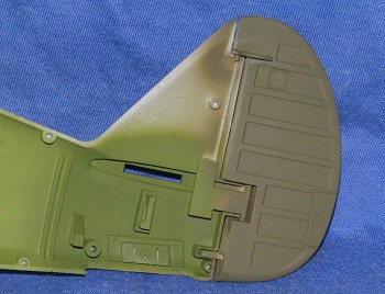
 The result on this side was plastic
card, superglue and filler to take care of the gap. This also caused some
problems when trying to install the cowl flap part. I had to thin the
inside of this part where it slide into place in order to get it to fit.
The image to the right shows the filler needed for both the lower cowl
section and the wing/fuselage join. Actually, that was the only part of the
wing where I used filler. The tail planes were then tacked on so I'd have
enough airframe for some test flight. Feline strafing accomplished, removed
the tail planes and then moved to the upper cowl parts. The back half gets
the cowl guns with their incredibly long blast tubes. These were painted
gun metal and glued in place. I completely missed the windscreen which
should have
The result on this side was plastic
card, superglue and filler to take care of the gap. This also caused some
problems when trying to install the cowl flap part. I had to thin the
inside of this part where it slide into place in order to get it to fit.
The image to the right shows the filler needed for both the lower cowl
section and the wing/fuselage join. Actually, that was the only part of the
wing where I used filler. The tail planes were then tacked on so I'd have
enough airframe for some test flight. Feline strafing accomplished, removed
the tail planes and then moved to the upper cowl parts. The back half gets
the cowl guns with their incredibly long blast tubes. These were painted
gun metal and glued in place. I completely missed the windscreen which
should have
 been
glued on at this time and it caused me some additional modifications a bit
later. I went to glue this on and it was obvious that it was a bit too
narrow. Now whether this was due to the part or my previous construction, I
don't know, but I clamped the fuselage to squeeze it down and glued on the
part. When dry, I fit on the upper cowling. Now this part is supposed to be
removeable so you can at least see some of your engine work, but mine just
refused to stay down, popping out of place in the front and not fitting
well in the back. I said goodbye to all that engine construction and
painting as I glued on the upper cowling.
been
glued on at this time and it caused me some additional modifications a bit
later. I went to glue this on and it was obvious that it was a bit too
narrow. Now whether this was due to the part or my previous construction, I
don't know, but I clamped the fuselage to squeeze it down and glued on the
part. When dry, I fit on the upper cowling. Now this part is supposed to be
removeable so you can at least see some of your engine work, but mine just
refused to stay down, popping out of place in the front and not fitting
well in the back. I said goodbye to all that engine construction and
painting as I glued on the upper cowling.
If you are going to glue on the upper cowling, all you need in terms of the engine are the basic block and the engine mounts. The block is needed to attach the exhaust stacks and the prop shaft. All that other stuff can be left off. Other bits glued on at this time were the fuel dump on the lower fuselage and the pitot tube on the wing. The etched gun sight and its plastic rod were also attached.
Now for the transparencies. As I'd already glued on the rear cowl section, I had to cut slots in the windscreen mounting tab to slide it in place. But before dealing with the clear bits, I masked off the cockpit and the wheel wells in order to paint this beastie.
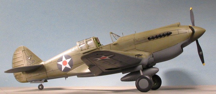
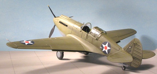
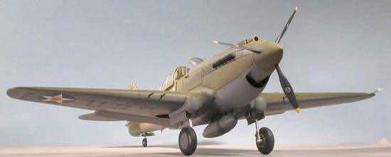
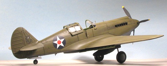
| COLORS & MARKINGS |
P-40s of this time period were deadly dull. At least those in Hawaii and the Philippines. We are talking OD over neutral grey with four insignia and the unit designators on the fin in black. No unit badges, not fancy nose art, no large white fuselage numbers. At least it makes painting easy. Now the instructions would have me paint the area behind the rear quarter windows with Interior Green. This would bring a huge number of e-mails telling me that is wrong, so I painted that area in OD. The rest of the paint job was easy, but took quite a bit of paint. I used some of my old Aeromaster acrylics for the Neutral Grey and used Testors Model Master OD for the upper bits.
 I'd already prepainted much
of the kit during the construction process so much of this had to do with
painting the areas yet untouched or where the paint had been sanded away. I
also masked the clear bits at this time. Windscreen and quarter windows
were a snap. The moveable canopy section wasn't. The panel lines on this
are not very crisp. There is no sharp delineation between frame and the
'glass'. It sort of flows from the frame onto the clear bits. This doesn't
make it easy to mask, regardless of what medium you are using. On all these
bits I first used Interior Green and then over-painted it with OD.
I'd already prepainted much
of the kit during the construction process so much of this had to do with
painting the areas yet untouched or where the paint had been sanded away. I
also masked the clear bits at this time. Windscreen and quarter windows
were a snap. The moveable canopy section wasn't. The panel lines on this
are not very crisp. There is no sharp delineation between frame and the
'glass'. It sort of flows from the frame onto the clear bits. This doesn't
make it easy to mask, regardless of what medium you are using. On all these
bits I first used Interior Green and then over-painted it with OD.
During this time, I painted the prop black, then masked it and painted the tips white which eventually got a yellow coating on them. When the paint dried, the areas to get decals were given a gloss clear coat.
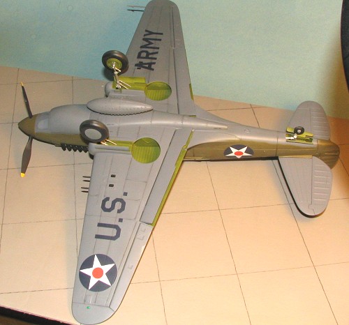
The decals are very well printed and are extremely thin. They went on well and succumbed to MicroSol without any fuss. The kit instructions are not good when it comes to these decals. Sure, it shows where the national insignia go as well as the fin markings, but there it basically stops. In the construction sequence it shows where the four 'fuel drain' decals go on the underside. Nothing is said about the two different sizes of insignia, or which goes where. The sheet doesn't differentiate between the sizes at all. I ended up using the bigger ones on the wings, but could have that reversed. I did this only because I put on the lower wing markings first and the first insignia I cut off was the larger one. I discovered the size difference only when I went to put on one of the fuselage insignia and the separate red center to the lower wing decals. It seemed too small, and then I realized what was going on. I should also mention that the 'U.S. Army' on the underside is in insignia blue. I believe this is the correct shade for camouflaged aircraft. If not, then this may be something you want to replace at a later date.
None of the other stencil decals have their locations shown and that includes the ones on the prop. I only used the Curtiss logos on the prop as I wasn't sure where the data stencils went. I just don't understand why the stencil placement information was missed and that is a hit on Vintage for this glitch.
| FINAL CONSTRUCTION |
OK, so I now have the decals on a pretty complete airframe. Nothing left but landing gear stuff and the assembling of the prop and spinner assembly.
The landing gear is such that it is
designed to allow you to remove the strut supports so that you can raise
the gear. Separate 'closed' gear doors are given to snap in place. That is
why the tail wheel door attachments are slots. The fit of the gear doors is
very tights to enable you to remove the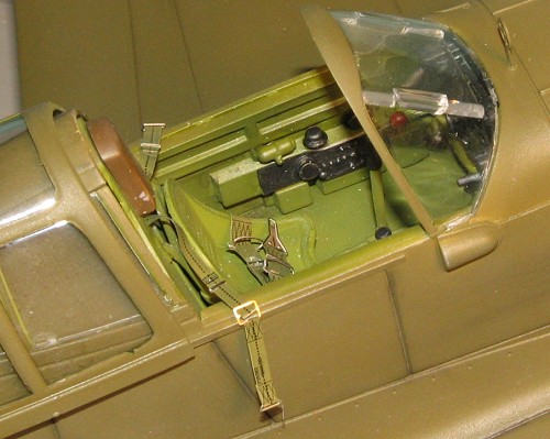 m.
Well, I'm not going to be doing a lot of playing with my P-40 so I attached
all the gears and struts to the main gear with glue. There is a strut that
goes from the small main gear door area to the main gear that I just
couldn't get to fit at all, so I left them off. The others were firmly
glued.
m.
Well, I'm not going to be doing a lot of playing with my P-40 so I attached
all the gears and struts to the main gear with glue. There is a strut that
goes from the small main gear door area to the main gear that I just
couldn't get to fit at all, so I left them off. The others were firmly
glued.
Getting the tires on the main wheels also took quite a bit of 'grunt'. Sort of like putting a tire on a bicycle wheel. I had to use a small screwdriver to help out. The rear tire is solid and simply gets trapped between the strut and hub part. Not a great fit this one. Once all the wheels were assembled, they were glued in place. There is a stub that keeps them from rolling.
I next glued on the windscreen, fit very good, followed by the quarter windows. Fit of these is quite good as well. These were attached using white glue.
The prop assembly is pretty straight forward, but the images in the instructions are not exactly like the parts themselves. One shouldn't have too much trouble figuring out what part goes where, but it would help if the drawings more closely approximated the actual bits. There is a circular spacer with holes in it that seems to have no real purpose, but I dutifully glued it in place anyway. The assembly just fits into the shaft hole on the end of the engine. Fit is good and if this prop is supposed to turn, I somehow missed that part of the assembly process. I then simply plugged in the drop tank. This item looks like no P-40 drop tank I've ever seen. It has huge raised rivet-looking things all over it and the seam runs on the top and bottom of the tank. Replace it as soon as an aftermarket is available.
The kit then had a clear matte coat sprayed on it and some final touch up painting was done. The last thing was to do the exhaust staining and some pastel panel line work (an easy job with these large engraved panel lines).
| CONCLUSIONS |
This one is a bit difficult to pigeon-hole. I think that the best way to describe it is that it is a kit that has traded in some fidelity to detail in terms of the smaller bits for ease of construction. The only other 1/24 kit I've built is the Trumpeter Bf-109G-6 so some comparisons are in order with that.
I like that this one doesn't have the complicated hinge work of the 109. However, it would have been nice to have the flight control surfaces so they could be placed in something other than the neutral position. The way the flaps are is not well thought out. Were I to do this kit again, I'd cut off the mounting tabs and install them at a later date. The current design makes it near impossible to glue the aft part of the wing and though P-40s were not usually seen with lowered flaps, I do believe they deployed at a greater angle than that given in the kit.
 The
retractable landing gear is a nice addition, if a bit on the 'gadget' side
of things. I don't think many will take advantage of this option, but it is
nice to have. I appreciate not having vinyl 'wiring' as was given on the
109, however, I also feel that a side panel should have been separate so
that the engine could be displayed. Having an upper cowl removable still
leaves most of the engine hidden.
The
retractable landing gear is a nice addition, if a bit on the 'gadget' side
of things. I don't think many will take advantage of this option, but it is
nice to have. I appreciate not having vinyl 'wiring' as was given on the
109, however, I also feel that a side panel should have been separate so
that the engine could be displayed. Having an upper cowl removable still
leaves most of the engine hidden.
Interior detail is not bad, and comparing it with the 109, in many ways it is superior. I'd highly recommend that Vintage add a set of seat belts to their next large kit, even if they have to hire Eduard to do them. Some may also think that the panel lines are a bit overdone, but they work OK for me. Finally, there really needs to be a good decal placement guide. Not having a way to tell where the stencils go is an oversight that needs to be corrected.
OK, for the bottom line, one has to consider a couple of things. First of all, this is a first kit and so overall, the impression left is quite good. The lack of any major fit problems (aside from the front of the lower wing deal I discussed in the build), makes this a kit that even those with not that much experience with complex kits will be able to complete and have look good when done. Secondly, the folks at Vintage are aiming at a rather specialized market with this kit. Not many people build these huge scale kits because space is generally a concern for most of us. I have considerably more shelf space than the average modeler and I'll have a bit of concern as to where to put this.
Taking both of those into account and looking back on the build, I'd have to say that Vintage is off to a great start. This kit was a lot of fun to put together, offered little in the way of major construction challenges and best of all, really looks the part when it is finished. If you think that 1/32 is 'small scale', then this kit is for you!
July 2005
#1372 in a series
Copyright ModelingMadness.com. All rights reserved. No reproduction in part or in whole without express permission from the editor.
If you would like your product reviewed fairly and fairly quickly, please contact the editor or see other details in the Note to Contributors.