| KIT: | |
| KIT #: | |
| PRICE: | |
| DECALS: | See review |
| REVIEWER: | Candice Uhlir |
| NOTES: | Scratch-built |
| HISTORY |
The Airco DH-10 evolved from a number of heavy bomber projects, starting in mid-1915. Geoffrey de Havilland’s DH-3 was designed to weigh 7000 lbs and to carry 5,000 lbs of “ballast”, otherwise known as “bombs”. A prototype was built and evaluated.
 In 1917, a re-design of the DH-3 resulted in the specification for the
DH-10. The first DH-10 prototype was flown in March 1918. That same
month, a contract was signed for 600 DH-10s. The aircraft’s active service
in World War I consisted of a single raid against German targets on Nov.
10, 1918. The next day the war was over and the production contracts for
DH-10s were subsequently canceled.
In 1917, a re-design of the DH-3 resulted in the specification for the
DH-10. The first DH-10 prototype was flown in March 1918. That same
month, a contract was signed for 600 DH-10s. The aircraft’s active service
in World War I consisted of a single raid against German targets on Nov.
10, 1918. The next day the war was over and the production contracts for
DH-10s were subsequently canceled.
As an example of how excited the R.A.F. was about this aircraft, monthly production was scheduled to attain 800 aircraft a month, which would result in eight bomber squadrons and three anti-submarine squadrons. Before the contracts were canceled, approximately 236 aircraft were delivered.
The DH-10 served with the RAF until 1926, serving primarily in Middle Eastern squadrons
| THE MODEL |
I
never really thought I would ever scratchbuild a model. Never say never -
here is my very first scratchbuilt model and it started out as me fooling
around with stuff while contemplating what my next kit project would be.
I had just finished an extensive kit modification that involved a bunch of scratch building but still, it was a kit.
That kit was a
1/48 Vickers Vimy resin kit that
turned out okay. I had a bunch of problems with that kit and I had to
scratch build a bunch of components just to
 achieve a reasonable model.
After completing that beast, I kept thinking of what I could have done
better, based upon what I learned over the course of that difficult build.
achieve a reasonable model.
After completing that beast, I kept thinking of what I could have done
better, based upon what I learned over the course of that difficult build.
At the same time I was looking for my next project. Since I had just finished the Vimy, I figured I could build my Aurora DH-10 and clean it up so I would have two British WW1 bombers. However, as I examined the Aurora kit and compared it to the Datafile photos, I realized that perhaps a flat sided WW1 bomber would be a natural first scratch build, especially since the wings are simple too. Best of all I had already built smaller parts such as stabilizers, tails surfaces, and other detailed components since starting the hobby. The only essential ingredients, besides plastic and my spare part box was the DH10 Datafile. Since I was only fooling around, why not experiment and see what comes about. My plan was to try scratch building each major component as if I were building a kit. If any portion came about as being too difficult I would just stop, put it away, and build a kit from the stash. I thought that in maybe two - perhaps three - days I would give it up.
| CONSTRUCTION |
Building the fuselage:
The fuselage is actually composed of two distinct portions. The lower half is mostly flat sided and I could build that without vacuforming any portion of it. The upper portion of the fuselage is curved but is small enough in area that I could quickly mold and vac the upper portion in pieces.
 To
avoid carving an entire fuselage from wood, I took advantage of an off
-scale drawing of the original DH10 fuselage structure. I scaled out this
drawing using my scanner. I then made a template of the upper and lower
fuselage from both a bottom up and a top down view from the Datafile. This
yields the fuselage shape when looking down or up.
To
avoid carving an entire fuselage from wood, I took advantage of an off
-scale drawing of the original DH10 fuselage structure. I scaled out this
drawing using my scanner. I then made a template of the upper and lower
fuselage from both a bottom up and a top down view from the Datafile. This
yields the fuselage shape when looking down or up.
.030 Plastic rod was used for the internal fuselage structural members. The distinctive “nose up” of the lower fuselage was achieved by building the fuselage upside down with the top of the fuselage taped flat to a piece of glass.. This kept the structure from flexing out of shape. Once done, I added .030 plastic card as the “skin” and the entire structure stiffened up appreciably.
The nose portion with the glass areas had to be worked and puttied a bit to get a nice curved surface and the “glass” is vacuformed clear plastic sealed with Krystal Kleer.
The upper curved portions of the fuselage are vacuformed using a small vac tool from Kingston Vac Works powered by a shop vacuum.
The upper portion had to be molded to achieve a basic form that I could putty and shape. This consisted of 6 individual molds cut from a product called “Balsa Foam”. This is a spongy block of balsa shavings and other “stuff” that cuts easily and that 600 grit sandpaper can quickly shape. It is also pretty soft, and if you are not careful you can dent it with moderate finger pressure. This stuff is so easy to mold that each of the 6 molds took less than 20 minutes each to cut, fit, and correct until I got the fit I wanted. I then taped these to the lower fuselage half to ensure a fit ready for putty.
Besides getting the basic shape of the aircraft correct, I quickly discovered that you must make allowances for mounting wings and other portions to the fuselage. With kits, we have it easy. Here, I had to ensure where the wings would mount and not distort the fuselage. This called for added structural strength at critical joints.
 The lesson learned was that - when scratch building - you have to think 5
steps ahead to avoid going down a dead end.
The lesson learned was that - when scratch building - you have to think 5
steps ahead to avoid going down a dead end.
The fuselage took about 2 months to build, spending about 8 to 10 hours a week. Interior details are mostly from my spare parts box or scratch built.
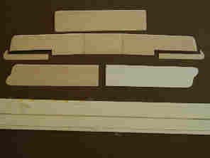
Building a Good Set of Wings:
The wings are plastic covered balsa wood cores. Mr. Frank Falco graciously spent some time with me at a past model show to explain how he made his wings from scratch and I used his technique on this project. The top and bottom wings are similar in construction, so I will concentrate on the top wing.
The lower wing surface is .040 stock cut to the wing outline in the Datafile. The leading edge is plastic, glued to the lower surface. Take this assembly and then bend it over a small piece of dowel to form the proper wing camber. Once the correct your camber is achieved, seal the camber in place using Cyanoacrylate glue to attach the balsa core to the lower plastic wing surface, and also butt the balsa up against the plastic leading edge.
You have to keep the camber bent as the CA cures because it is the balsa glued to the lower surface that keeps the camber fixed. A slower drying CA is best here to allow for adjustment of the wood core.
 Dihedral was achieved by filing out a V groove in the wood core where
needed and applying dihedral. The groove was sealed with Balsa dust and
white glue. The balsa core is removed about one-half inch from the
trailing edge. This allows the upper and lower plastic wing surfaces to
meet in a nice sharp trailing edge. I put a piece of plastic rod inside
here (remember to think ahead!) to give me a bit more material to sand down
and shape the airfoil properly.
Dihedral was achieved by filing out a V groove in the wood core where
needed and applying dihedral. The groove was sealed with Balsa dust and
white glue. The balsa core is removed about one-half inch from the
trailing edge. This allows the upper and lower plastic wing surfaces to
meet in a nice sharp trailing edge. I put a piece of plastic rod inside
here (remember to think ahead!) to give me a bit more material to sand down
and shape the airfoil properly.
 The
top of the wing was skinned with .030 plastic sheet. I used this thinner
material so I could cover the top using a single piece of plastic and avoid
another set of seams to sand down. A bit of custom work and putty at the
wing tips and - after only four sets of wings later - I finally had a set
good enough to use on the model.
The
top of the wing was skinned with .030 plastic sheet. I used this thinner
material so I could cover the top using a single piece of plastic and avoid
another set of seams to sand down. A bit of custom work and putty at the
wing tips and - after only four sets of wings later - I finally had a set
good enough to use on the model.
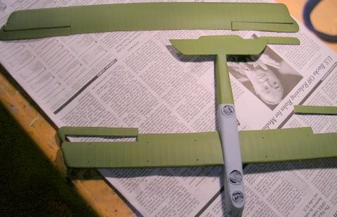
The rib-tape effect was done using narrow strips of vellum attached with white glue and coated with 4 or 5 coats of auto primer to seal the edges, as explained by John Alcorn in his book, “The Master Scratchbuilders.”
The Rest of the “kit”:
From this point on, I knew I could make all the remaining components from scratch since I have done that many times over the years to replace parts from a kit that were missing or substandard. Now it was a question of whether I had engineered the structure sufficiently to support the rest of the model. The “thinking ahead” part became painfully critical.
I
experienced some flexing of the fuselage when I mounted the lower wings and
had to spend some time sealing flex cracks in the skin. I had to face this
basic difficulty every time I mounted a new component to the fuselage but
eventually you know what to look for.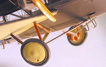
The elevators and rudder are made from .040 plastic stock. The wing struts are bamboo where a wood look is needed. The landing gear consists of wood and brass rod cut to fit.
DH-10 wheels are bigger than anything I could find in my parts box or any of my WW1 kits in the stash. I ended up scratch building the wheels from plastic disks cut out with a circle cutter in decreasing radius to achieve the “cone” shape. The rims are small pieces of plastic strip, while the tires are rubber 0-rings.
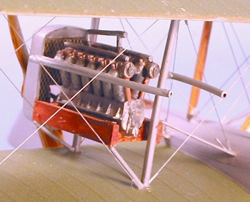
The cabane fairing under the top wing is vacuformed, with the mold created using Balsa Foam. The radiators are scratchbuilt, complete with brass screening visible under the louvers. The louvers are made from vellum strips.
 The most difficult part of this project was the detail of the louvers.
What I ended up with aren’t exactly right, but since I attached them to the
radiator using white glue I can just pop them off if I ever get my louver
building skill up to par.
The most difficult part of this project was the detail of the louvers.
What I ended up with aren’t exactly right, but since I attached them to the
radiator using white glue I can just pop them off if I ever get my louver
building skill up to par.
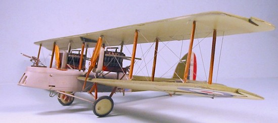
 The rest of the airplane is pretty basic: Aeroclub Liberty engines,
exhausts from cut brass rod, with the guns and Scarff rings also by
Aeroclub.
The rest of the airplane is pretty basic: Aeroclub Liberty engines,
exhausts from cut brass rod, with the guns and Scarff rings also by
Aeroclub.
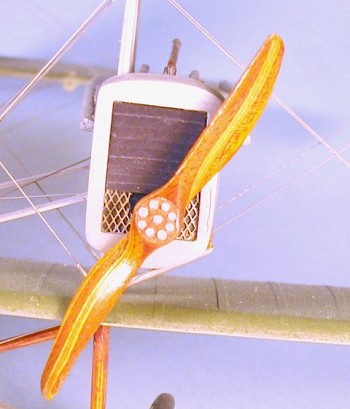
The propellers are the result of my first attempt at hand carving wood
props. They consist of laminates of 1/32 mahogany and 1/32 aircraft grade
plywood. I wanted walnut instead of plywood but I couldn’t find it. These
two props are attempts number 4 and 5. Once I got the hang of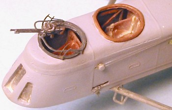 how the
props are detailed in the Datafile drawings, these are pretty easy to make
accurately. After awhile, I discovered the laminate serves to allow you to
gauge symmetry. Each prop was done using my Dremel for fast shaping, and
sandpaper for final details. They were varnished with Tamiya “Clear
Yellow,” followed by a final coat of Future to shine them up. The grain
effect is just amazing. I think I am hooked on this wood prop thing. It
looks so much better than painting.
how the
props are detailed in the Datafile drawings, these are pretty easy to make
accurately. After awhile, I discovered the laminate serves to allow you to
gauge symmetry. Each prop was done using my Dremel for fast shaping, and
sandpaper for final details. They were varnished with Tamiya “Clear
Yellow,” followed by a final coat of Future to shine them up. The grain
effect is just amazing. I think I am hooked on this wood prop thing. It
looks so much better than painting.
| COLORS & MARKINGS |
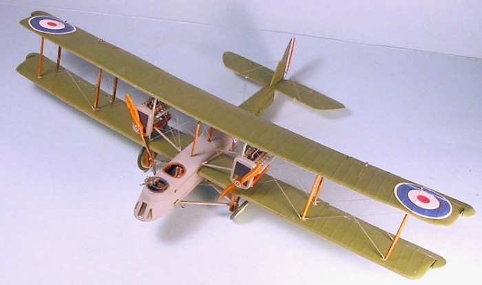
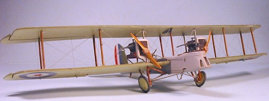
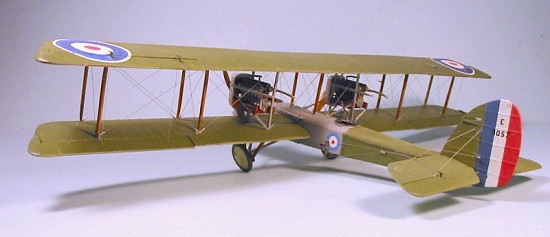
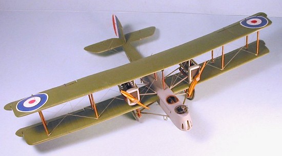
This aircraft represents E9057 as it existed in 1919. This was the first Daimler-built DH-10. The primary colors are PolyScale Grey, and PolyScale PC10.
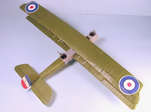
I airbrushed the wing roundels directly onto the wing, using a 4-step Frisket-masking method. Frisket masks were cut with a circle cutter. The rudder stripe insignia is airbrushed. The fuselage roundels and serial numbers are from my spare decal stash.
I rigged the model with stainless-steel wire, using my method of adding rubber hosing to each tip to simulate the stanchions and allow for a good tight fit for the wing braces.
| CONCLUSIONS |
A year has passed since I started to “mess around” and the result is my 1/48 scale DH-10 “Amiens” Bomber.
 I
would strongly recommend a nice flat-sided World War I subject for an
initial scratchbuilt project. An inexpensive Vac machine is really the
only other equipment you need to come up with a nice model.
I
would strongly recommend a nice flat-sided World War I subject for an
initial scratchbuilt project. An inexpensive Vac machine is really the
only other equipment you need to come up with a nice model.
This was definitely more expensive than any mass produced kit, but the rewards are far more substantial. This one is uniquely mine and represents a lot of firsts for me. Without this project, I doubt I would have stretched my abilities anywhere near what I did here.
Special thanks go to Mr. Frank Falco for sharing his wing building technique with me and providing me with project notes. Mike Robinson of the WW1 List helped me achieve a nice sharp trailing edge with his excellent suggestions. Thanks also to Tom Cleaver for encouragement throughout the project.
In closing, this project was tremendous fun. It is a real treat to have something uniquely yours and have it come out well. This was a wonderful way to break out of a rut and really extend my skills. For anybody who wants something different, try this! It is amazing how rewarding the project can be.
| REFERENCES |
Windsock Data File #38, Airco DH 10; J.M. Bruce.
September 2005
Copyright ModelingMadness.com. All rights reserved.
If you would like your product reviewed fairly and fairly quickly, please contact the editor or see other details in the Note to Contributors.