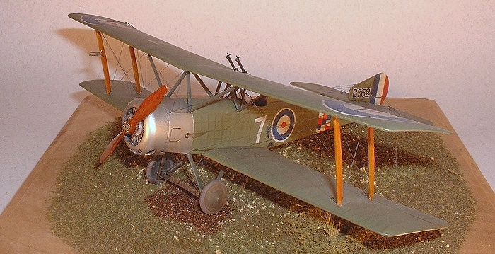
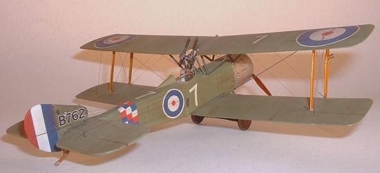
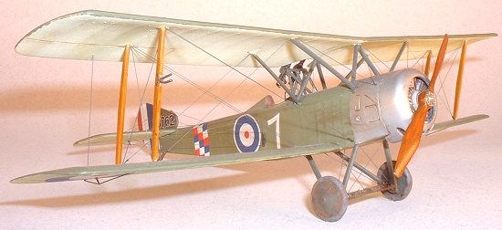
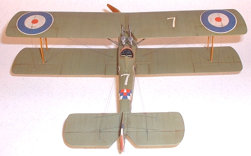
Roden 1/48 1 1/2 Strutter Comic Night Fighter
| KIT #: | ? |
| PRICE: | $19.96 MSRP ($17.96 at Squadron) |
| DECALS: | Two options |
| REVIEWER: | Michael Moore |
| NOTES: |
| HISTORY |
Tom Cleaver covered this well in his review of the two- seat fighter. So rather than paraphrase the Windsock Data File, I’ll direct you to his review.
| THE KIT |
For a general idea of what is in the box, see Scott's preview. Most of the plastic and etch in this kit is the same, the main difference being a sprue with the single place upper decking. One nice thing is that Roden abandoned the clear plastic fuselage and wings. In their place is a nice gray plastic. The decals of course are different.
| CONSTRUCTION |
 Like most every aircraft
model I started on the cockpit. First off I painted the interior. The
fuselage got a coat of Polly S Clear Doped Linen. The wood framing and
floor got British Dark Earth and Middlestone respectively. They were just
handy brown tones I used to simulate wood. A light oil wash on the
fuselage sides wrapped that part up. Once painted, the fuselage halves get
glued together as the cockpit assembly drops in before the upper decking is
installed.
Like most every aircraft
model I started on the cockpit. First off I painted the interior. The
fuselage got a coat of Polly S Clear Doped Linen. The wood framing and
floor got British Dark Earth and Middlestone respectively. They were just
handy brown tones I used to simulate wood. A light oil wash on the
fuselage sides wrapped that part up. Once painted, the fuselage halves get
glued together as the cockpit assembly drops in before the upper decking is
installed.
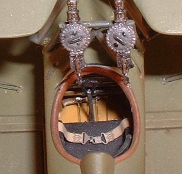
The photo etch instrument panel I painted in Polly S Grimy Black with night black instrument faces. When all that dried I lightly sanded the surface to expose the brass to out line the bezels and wiring. Drops of Future in the instrument faces completed the panel. The rudder bar is brown with silver highlights and the control stick is gray with a black grip. Even though it looks pretty lame I painted the kit seat flat black and dressed it up with a spare lap belt. I’ve got to remember to pick up some British WWI seats before I build the two-seater!
Actual
construction then started. Be ready for a little trial and error here.
Ok, a lot. First off is the rudder bar and control lines. The lines are 2
lb fly fishing tippet line tied off to the rudder bar and glued into
notches carved into the back end of the floor. They are largely invisible
on the finished kit, but…I know they are there! Now for the instrument
panel. It is obviously designed to fit in the forward cockpit of a two
seater. It must be cut down flush with the plastic backing for it to fit
in the rear cockpit position. The rest of the cockpit installation is a
trial a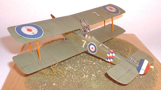 nd error loop.
After cutting down the instrument panel, you will quickly realize that the
locating holes for the seat in the aft cockpit mean nothing with this
version. They are for a four-legged stool in the two-seater. You will
also realize there are no locating marks, pins, tabs, or other clues to
guide where the floor goes. I dry fit everything until the cockpit seemed
to fit under the opening in the upper decking. I managed to mark the floor
and get it glued in at the aft end only. I then glued in the instrument
panel. As planned, the top edge was high. Next I used the upper decking
to push the instrument panel/floor assembly down to where it needs to be,
lifted the decking off and superglued the edge of the panel to the sides of
the cockpit. I needed super glue to fill the gap left after I remembered
to use a piece of sprue to spread the forward fuselage to match the width
of the upper decking (thanks TC). Of course I spread the fuselage AFTER I
cut down the instrument panel to fit the un-spread fuselage (I think there
is a lesson there somewhere)!
nd error loop.
After cutting down the instrument panel, you will quickly realize that the
locating holes for the seat in the aft cockpit mean nothing with this
version. They are for a four-legged stool in the two-seater. You will
also realize there are no locating marks, pins, tabs, or other clues to
guide where the floor goes. I dry fit everything until the cockpit seemed
to fit under the opening in the upper decking. I managed to mark the floor
and get it glued in at the aft end only. I then glued in the instrument
panel. As planned, the top edge was high. Next I used the upper decking
to push the instrument panel/floor assembly down to where it needs to be,
lifted the decking off and superglued the edge of the panel to the sides of
the cockpit. I needed super glue to fill the gap left after I remembered
to use a piece of sprue to spread the forward fuselage to match the width
of the upper decking (thanks TC). Of course I spread the fuselage AFTER I
cut down the instrument panel to fit the un-spread fuselage (I think there
is a lesson there somewhere)!
 Now
the real fun starts. The seat will not fit through the cockpit opening of
the upper decking. So, drop the seat in and again set the decking in
place. Now, position the seat under the decking through the cockpit
opening, lift the decking, and, using your third hand, hold the seat in
place, remove the decking, and superglue the seat in place before you
slip. I got it on the third, no, fourth try. Now say five hallelujahs
that the cockpit is tight enough that most of us won’t be tempted to detail
it past lap belts and those rudder control lines that are pretty much
invisible. Once the cockpit was in I finally glued the upper decking in
place.
Now
the real fun starts. The seat will not fit through the cockpit opening of
the upper decking. So, drop the seat in and again set the decking in
place. Now, position the seat under the decking through the cockpit
opening, lift the decking, and, using your third hand, hold the seat in
place, remove the decking, and superglue the seat in place before you
slip. I got it on the third, no, fourth try. Now say five hallelujahs
that the cockpit is tight enough that most of us won’t be tempted to detail
it past lap belts and those rudder control lines that are pretty much
invisible. Once the cockpit was in I finally glued the upper decking in
place.
The next challenge is getting the tail planes in place. Some work with sanding sticks on the aft end of the fuselage, and the tail planes fit pretty well. Then it’s on to the rudder. Once I got mine permanently mounted I’d somehow lost the gap between it and the tailplanes. I can only say that I intentionally modeled the aircraft with its revolutionary variable incidence tailplanes in the fully raised position!
 Before mounting the
lower wing I carved and sanded off the molded fairleads on the fuselage
sides for the tailplane rigging. Due to the aft cockpit arrangement of the
flying controls, the elevator wires were attached to toggles mounted aft of
the cockpit. The kit includes the toggles, but no mention is made of
removing the molded fairleads. I thought the kit-supplied toggles were a
bit on the heavy side so I scratch built new ones out of styrene rod and
card. In the end I realized I probably could have gotten the same effect
with less work by just sanding down the kit part.
Before mounting the
lower wing I carved and sanded off the molded fairleads on the fuselage
sides for the tailplane rigging. Due to the aft cockpit arrangement of the
flying controls, the elevator wires were attached to toggles mounted aft of
the cockpit. The kit includes the toggles, but no mention is made of
removing the molded fairleads. I thought the kit-supplied toggles were a
bit on the heavy side so I scratch built new ones out of styrene rod and
card. In the end I realized I probably could have gotten the same effect
with less work by just sanding down the kit part.
The lower wing fits very well, only needing a bit of dry fitting and sanding to leave a join needing no filler. I did use a bit of filler on the bottom of the fuselage and on the top. Go easy on the top though to avoid losing the stringer detail.
| COLORS & MARKINGS |
Paint:
At this point most everything was ready for the paint shop. After pre-shading all the rib and control surface joints, I sprayed the lower surfaces with Polly S CDL and the upper surfaces with Polly S PC 10. I lightened the PC 10 with a little yellow and sprayed between the wing ribs for a little more contrast, and then blended it all with a thin mist of the lightened mix over all the PC 10.
More Construction:
 I then tackled the
engine. Once cleaned up and painted, it looks quite convincing to me. It
is painted in gray, silver, copper, and heavily washed with black oils.
After waiting over night, I dipped a q-tip in some thinner and cleaned up
the cylinder fins. Before adding the etched wiring harness I picked out
the engine bolt heads with some chrome silver to really make them stand
out.
I then tackled the
engine. Once cleaned up and painted, it looks quite convincing to me. It
is painted in gray, silver, copper, and heavily washed with black oils.
After waiting over night, I dipped a q-tip in some thinner and cleaned up
the cylinder fins. Before adding the etched wiring harness I picked out
the engine bolt heads with some chrome silver to really make them stand
out.
Be careful with the wiring harness. It probably won’t fit over the propeller shaft. I Sanded down the plastic part, but went too far and when the plastic cap (part 4E) was fitted there were gaps. I filled them with superglue, but couldn’t sand it with out losing the bolt detail on part 4E. It’s largely hidden behind the propeller on the finished model, but next time I would try to open up the center of the wiring harness with a round file before removing it from the fret.
Before gluing the engine I painted the front end of the fuselage silver. Also, be sure test fit the engine and cowling to make sure that part 8I isn’t too thick. If all glued up first you will end up with a very difficult fix. Also, thanks again to TC and his earlier review. The cowling is too small. Don’t glue it up and then glue it to the fuselage. Glue it to the fuse in sections and fill the gaps.
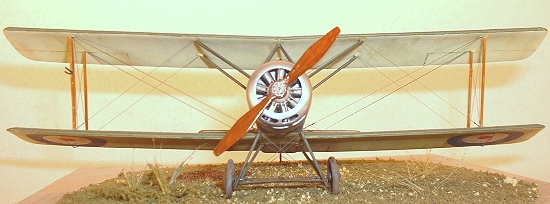 Now it’s time for more
painting. I masked the engine with a circle of plastic baggie tucked under
the cowling and shot the cowling and forward fuselage Model Master
non-buffing steel and sealed it with metalizer sealer. I also painted the
cabane struts, landing gear struts, and gun mounts Polly S British Dark
Green for some contrast with the PC 10 airframe. Finally, the interplane
struts and propeller got a coat of medium tan acrylic (I forget now EXACTLY
which tan) in preparation for a faux wood treatment with oils. The oils
are a mix of Yellow Ochre, Raw Umber and Burnt Sienna brushed on the parts,
and then pulled thin and streaky with a paintbrush to simulate wood grain.
Here is a much better explanation (http://www.ipmsstockholm.org/magazine/2003/03/stuff_eng_tech_wood_grain.htm).
Most of the pictures in the Datafile actually look like the propellers were
painted. While that let me off the hook on trying to simulate a laminated
propeller, I did decide to do it as varnished wood for more interest and I
also made the prop darker than the interplane struts. The finishing touch
is some Tamiya clear yellow to simulate varnish. Just make sure to wait
for the oils to dry, which will take a few days.
Now it’s time for more
painting. I masked the engine with a circle of plastic baggie tucked under
the cowling and shot the cowling and forward fuselage Model Master
non-buffing steel and sealed it with metalizer sealer. I also painted the
cabane struts, landing gear struts, and gun mounts Polly S British Dark
Green for some contrast with the PC 10 airframe. Finally, the interplane
struts and propeller got a coat of medium tan acrylic (I forget now EXACTLY
which tan) in preparation for a faux wood treatment with oils. The oils
are a mix of Yellow Ochre, Raw Umber and Burnt Sienna brushed on the parts,
and then pulled thin and streaky with a paintbrush to simulate wood grain.
Here is a much better explanation (http://www.ipmsstockholm.org/magazine/2003/03/stuff_eng_tech_wood_grain.htm).
Most of the pictures in the Datafile actually look like the propellers were
painted. While that let me off the hook on trying to simulate a laminated
propeller, I did decide to do it as varnished wood for more interest and I
also made the prop darker than the interplane struts. The finishing touch
is some Tamiya clear yellow to simulate varnish. Just make sure to wait
for the oils to dry, which will take a few days.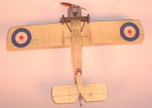
Decals and Weathering:
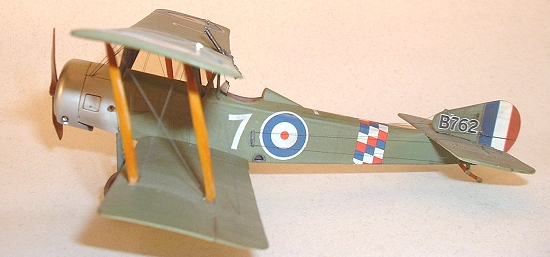
Now, before going any further I decided to brave the decals. In short, they are very hit and miss. My first set was absolutely unusable. Fortunately, an email to Roden and a two week wait got me a replacement set that at least didn’t shatter completely on sensing water. I actually like the decals though. They are very thin and opaque and the color is just a bit inconsistent; they almost look pre-weathered. There are only a couple of problems. The fuselage roundels are quite a bit too large, and shouldn’t wrap over onto the top of the fuselage and I would recommend painting the red, white and blue stripes on the tail; the decals don’t really fit well and I ended up having to touch up the edges with paint. After getting the decals on and sealed it was in fact, time for weathering. Once the kit is together and rigged, it’s hard enough to pick up, let alone weather. For the weathering I first ran a Burnt Umber wash into all the control surface joints. I then used red and brown chalk pastels to highlight the rib and stringer detail. I found the best way to do this was to just get my finger dirty and lightly rub the model. Sort of dry brushing with your finger.
| FINAL CONSTRUCTION |
The
upper wing proved to be a bit of a challenge to get in place. I was
worried about getting everything properly aligned. The upper wing sits
forward of the lower wing, and while the aft cabane struts lean forward,
the forward cabanes lean aft! I first tried setting the cabanes on the
fuselage using plastic card templates to set the proper angles in relation
to the fuselage. That proved for some reason to be too delicate, and when
I tried to set the upper wing the whole mess wobbled until the cabanes
broke off the fuselage. After I cooled off for a day or two I returned to
try gluing the cabanes to the upper wing using my MK I eyeball to judge the
angles, and a pair of dividers to make sure the spacing at the fuselage
attachment 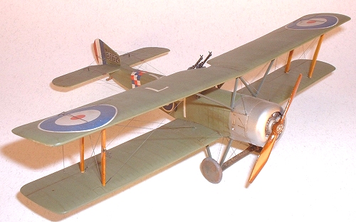 points was
right. This proved to be far more robust and I was able to get the
assembly superglued to the fuselage. From there I got the interplane
struts glued into place. Somehow the gods were with me, and the upper wing
was properly aligned. I think next time some sort of jig will be safer, as
I’m usually not that lucky.
points was
right. This proved to be far more robust and I was able to get the
assembly superglued to the fuselage. From there I got the interplane
struts glued into place. Somehow the gods were with me, and the upper wing
was properly aligned. I think next time some sort of jig will be safer, as
I’m usually not that lucky.
Now it’s time for rigging. I really like using fishing line and pulling it tight through pre-drilled holes. I rigged this plane with a combination of 4 lbs Fly Fishing Tippet (thanks Dad) and smoke colored invisible thread. Even though it doesn’t probably reflect reality, the different sized line breaks up the rigging a bit and looks good to me. The turnbuckles are twisted thread, a technique I found here (http://www.ipmsstockholm.org/magazine/2001/11/stuff_eng_tech_rigging.htm). The rigging was painted in place with Polly S Grimy Black and the turnbuckles were picked out in Polly S Night Black. The etched rigging pieces for the flaps, elevator and rudder worked very well but I found it much easier to tie the rigging to the etched pieces for the tail controls before removing them from the fret. I would also highly recommend the Windsock Datafile as a reference. The kit instructions don’t have a rigging diagram, and the box art can be hard to decipher. For instance the aft flying wires actually pass completely through the lower wing and terminate on the landing gear struts, not at the lower wing. I also did not use the etched pieces Roden provides for rigging terminations. After looking at the Datafile, I thought running the rigging into the wings was more realistic, and easier.
 Next up is the landing
gear. The attachments are very insubstantial, and the assembly is fussy.
Thanks here to Bob Laskodi for his landing gear jig. I marked a small
Styrofoam block with the proper fuselage spacing and inserted the fuselage
ends of the struts into the block. Then the axle can be glued into place
to set that spacing and keep the whole mess square. Keep in mind that the
Strutter, like many Sopwith aircraft had a split axle. To replicate this I
cut, carved and sanded off the molded plastic axle, and replaced it with
brass rod. Despite my efforts, I didn’t get the wheels set with the tops
leaning in like they should be. After getting the landing gear tacked into
place, I ran small fillets of superglue around the struts where they attach
to the fuselage to improve their strength. Although it’s still a bit
wobbly, I found that the rigging really beefs up the assembly, just like
the real thing, and a good reason in my book to rig with thread pulled
tight.
Next up is the landing
gear. The attachments are very insubstantial, and the assembly is fussy.
Thanks here to Bob Laskodi for his landing gear jig. I marked a small
Styrofoam block with the proper fuselage spacing and inserted the fuselage
ends of the struts into the block. Then the axle can be glued into place
to set that spacing and keep the whole mess square. Keep in mind that the
Strutter, like many Sopwith aircraft had a split axle. To replicate this I
cut, carved and sanded off the molded plastic axle, and replaced it with
brass rod. Despite my efforts, I didn’t get the wheels set with the tops
leaning in like they should be. After getting the landing gear tacked into
place, I ran small fillets of superglue around the struts where they attach
to the fuselage to improve their strength. Although it’s still a bit
wobbly, I found that the rigging really beefs up the assembly, just like
the real thing, and a good reason in my book to rig with thread pulled
tight.
And the fussy assemblies don’t stop quite yet. I had decided to do B’762 because I thought the twin Lewis guns set to fire over the upper wing looked much cooler than a single Vickers set to fire through the propeller arc. Be warned, the kit gun struts will not fit. At least not as molded. They have to be cut down and worked around the aft anti-drag wires and behind the aft cabanes. And even once that is done, they are very oversized. If you were set up for and capable of it, a better option would be to solder some stiff wire into the correct assembly. It doesn’t have to be too substantial, as it only has to support the plastic Lewis Guns.
| CONCLUSIONS |
All in all I didn’t find the kit as difficult to build as it may sound. Most of the fit was very good and the moldings are very clean. The difficult parts were not impossible, just a challenge. And the end result is a very nice model on my shelf. For the price, you really can’t beat it.
| REFERENCES |
Windsock Datafile and various photos on the internet.
March
2005 If you would like your product reviewed fairly and
fairly quickly, please
contact
the editor or see other details in the
Note to
Contributors.