Airfix 1/72 DH.4
| KIT #: | 01079 |
| PRICE: | $ |
| DECALS: | One option |
| REVIEWER: | Stephen Foster |
| NOTES: |
| HISTORY |
The Airco DH 4 was
designed and first flown in 1916 and was originally intended to be powered by
the new 230hp BHP engine, but production delays meant that the Rolls Royce 250
hp Eagle engine was fitted to the second prototype, resulting in an outstanding
aircraft. It was quickly brought into service in France in March 1917 with 55
Sqdn. RFC where it was found to be so fast that it could operate without fighter
escort, a feat repeated in a later conflict by the same company's Mosquito. In
fact the supply of engines was a problem for this aircraft and a variety of
engine types were fitted at different times including the Rolls Royce Eagle VIII
and the less reliable and powerful RAF 3a among others. With the Eagle VIII the
DH 4 c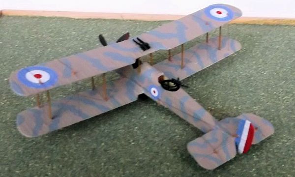 ould reach 133 mph and had a ceiling of 23000 feet. One modification which
was made to production machines at the end of 1917 was to change the fuel system
from a pressurised system to one driven by wind pumps on the fuselage behind the
pilot's cockpit: if you wish to model a later production machine you will have
to add these wind pumps as they are not provided in the kit.
ould reach 133 mph and had a ceiling of 23000 feet. One modification which
was made to production machines at the end of 1917 was to change the fuel system
from a pressurised system to one driven by wind pumps on the fuselage behind the
pilot's cockpit: if you wish to model a later production machine you will have
to add these wind pumps as they are not provided in the kit.
The remarkable
qualities of this machine were quickly noted by the American air service who
ordered it into production in America, (the only British designed machine to be
so produced), where 1885 machines were built and delivered to France before
November 1918. In Britain a further 1449 machines were built and delivered.
These aircraft were used in a variety of roles including bombing, photographic
reconnaissance, anti-submarine patrols, anti-Zeppelin patrols, ambulance and
passenger carrying, etc. on the western front and in other theatres of WWI. Two
RAF 3a engined aircraft were to have carried out a photographic reconnaissance
sortie over the Kiel Canal in August 1917 but this was abandoned due to the
unreliability of the engines: instead one (A7459) was equipped with two Lewis
guns on the top wing and used in the anti-Zeppelin role. It is thought that it
was this machine that attacked L44 on 5th Sept 1917 and later ditched in the
North Sea following engine failure. On August 5 1918 Majors Leckie and Cadbury
managed to shoot down L70 into the North Sea and it is markings for their
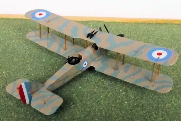
aircraft which are provided in the kit. I chose to modify my own model to
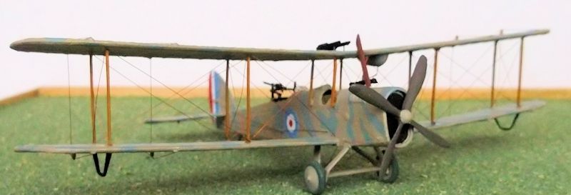
represent the RAF 3a engined A7459.
Following
the cessation of hostilities in 1918 many DH 4's were sold to air forces in
Chile, Belgium, Iran, Greece and Spain, or were converted to civilian use.
| THE KIT |
This kit was originally released in1968 and has been re-issued several times since. It has not been retooled but apart from a few minor mould marks it is a well produced kit with no flash and some very good parts, especially the guns which are a real bonus. On the other hand the cockpit detail is missing except for the seats and the surface detail is over heavy - the ribs need sanding down and the trenches on the fuselage need filling: these are typical features of kits of this time and should not put any serious modeller off. There are a total of 40 parts which fit together well except for the horizontal tail surfaces which need filler where they join the fuselage. The markings provided are for an aircraft flown by Maj. Leckie with Maj. Cadbury as observer who shot down Zeppelin L70 in August 1918.
| CONSTRUCTION |
 Assembly is very
straightforward although unless you put the crew in you may wish to add some
detail to the cockpits. I added a small instrument panel in the front, together
with a control column, and ammunition racks in the rear cockpit. When you join
the fuselage you will need to run a little filler down the seam and sand off any
slight ridges. The lower wing joint also needs a tiny amount of filler. Remove
the moulded windscreen from the front of the gunner's cockpit and replace it
later with one made from thin acetate. Similarly remove the bomb-racks from
under the wing: these need to be replaced with ones that are oriented front to
rear and are made from 15 thou card. The tailplane joints definitely need filler
- this is probably the worst area of the kit. Some will also wish to remove the
over-thick control horns on all of the control surfaces and replace these with
new ones from thin card later.
Assembly is very
straightforward although unless you put the crew in you may wish to add some
detail to the cockpits. I added a small instrument panel in the front, together
with a control column, and ammunition racks in the rear cockpit. When you join
the fuselage you will need to run a little filler down the seam and sand off any
slight ridges. The lower wing joint also needs a tiny amount of filler. Remove
the moulded windscreen from the front of the gunner's cockpit and replace it
later with one made from thin acetate. Similarly remove the bomb-racks from
under the wing: these need to be replaced with ones that are oriented front to
rear and are made from 15 thou card. The tailplane joints definitely need filler
- this is probably the worst area of the kit. Some will also wish to remove the
over-thick control horns on all of the control surfaces and replace these with
new ones from thin card later.
I chose
my model to be an RAF 3a engined machine: this had a higher thrust line than the
later Eagle as represented in the kit so I had to make a new radiator from card
with the surface scored with a knife and a hole drilled in the centre to take
the propellor. I also had to make a new engine cowling from 40 thou card - I
made this in two pieces which I wrapped around the sides and joined at the top
and bottom. The joints were filled and sanded after the new piece had been
cemented to the nose. The exhaust pipe holes in the kit were filled and rubbed
down and and the engine vents on the top and bottom of the engine removed with a
file. A small slot was cut into the top of the engine to take the exhaust stack
which was made from 30 thou card. If you chose to model an Eagle engined
aircraft as per the kit, use the kit parts, although the ports for the exhaust
pipes are a little too large but they are difficult to rectify. NB that the
engine vanes as moulded on the kit represent an early Eagle engine and that this
is not correct for the
 markings provided. Most people probably would not notice
however. If you use the kit exhausts leave them off until you have painted the
model.
markings provided. Most people probably would not notice
however. If you use the kit exhausts leave them off until you have painted the
model.
The bars
on the struts which fit into the top wing make building this kit easy - they
were a novel feature in the late 1960's because until then modellers of biplanes
had to insert individual struts and try to get the correct stagger, which
required levels of skill beyond the average and made biplane models even more
unpopular. I recommend that you gently file the the strut bars before you cement
them into place - do a dry run to get them as near level with the wing surface
as possible. Glue all of the struts into place and ensure that they are at 90
degrees to the wing surface when observed from the front while they dry out.
Then apply small amounts of filler to fill any cracks, rub down and you will
have a very good finish to the bottom of the upper wing. The fuel tank is on the
wrong side of the wing if you follow the kit instructions. Correcting this is
simple - fill the locating holes in the wing, cut off the pins on the tank and
carefully glue the tank to the bottom of the wing but on the port (left) side
exactly opposite to where the kit suggests it should go. You may need a tiny bit
of filler here too. The main undercarriage also fits well - just a tiny amount
of filler perhaps around the fuselage may be necessary. If you wish to make an
accurate model of Leckie and Cadbury's machine you will need to modify the
engine outlets on the nose and add the two small generators on posts behind the
pilot's cockpit as shown on the box art.
| COLORS & MARKINGS |
I painted my
model before fitting the top wing as it makes life so much easier and with care
few marks need to be made on the paint when the final assembly takes place. Most
wartime D H 4's were finished in PC10 upper surfaces and fuselage sides aft of
the rear gunner's cockpit as per the instructions, with clear doped linen
undersurfaces. The metal parts of the forward fuselage were dark grey. Wheel
discs were PC10 as were the undercarriage legs. The tyres were dark grey and the
exhausts rust. Markings were as per the kit. Some DH 4's had variations on this
scheme - usually in the form of the PC 10 being painted
 over the metal parts of
the nose although the radiator cowling and top of the engine was also left grey
on some machines. In short if you wish to model a particular aircraft either
check some accurate illustrations or use a photograph of the original aircraft.
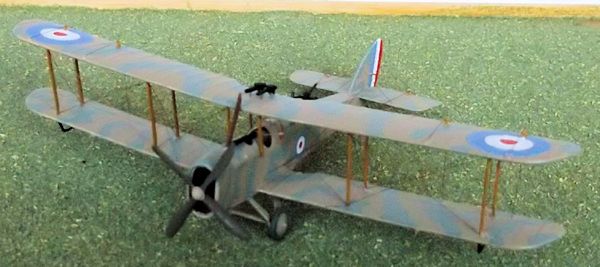
Struts were natural wood and the propellor dark brown. In my case I chose to
model A7459, one of two RAF 3a engined machines that were specially modified to
take part in a photographic reconnaissance sortie over naval bases east of the
Kiel Canal in August 1917, but the sortie was abandoned and this particular
aircraft was later equipped with two Lewis guns on the top wing and pressed into
service in the anti-airship role. The propellor had a small spinner which I
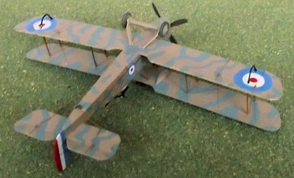
shaped from a small piece of scrap card. The camouflage pattern was beige/fawn
with a sky blue disruptive pattern on upper and under-surfaces. The roundels
were also sky blue and the outer one inch white circles on the top wing and
fuselage roundels were painted out. The serial was also overpainted. I hand
painted the markings on my model.
over the metal parts of
the nose although the radiator cowling and top of the engine was also left grey
on some machines. In short if you wish to model a particular aircraft either
check some accurate illustrations or use a photograph of the original aircraft.
Struts were natural wood and the propellor dark brown. In my case I chose to
model A7459, one of two RAF 3a engined machines that were specially modified to
take part in a photographic reconnaissance sortie over naval bases east of the
Kiel Canal in August 1917, but the sortie was abandoned and this particular
aircraft was later equipped with two Lewis guns on the top wing and pressed into
service in the anti-airship role. The propellor had a small spinner which I
shaped from a small piece of scrap card. The camouflage pattern was beige/fawn
with a sky blue disruptive pattern on upper and under-surfaces. The roundels
were also sky blue and the outer one inch white circles on the top wing and
fuselage roundels were painted out. The serial was also overpainted. I hand
painted the markings on my model.
| FINAL CONSTRUCTION |
Final assembly is
straightforward. The struts are easy to put into place - put a small drop of
glue into the location holes on the lower wing and put the ends of the struts
into them. The fuselage struts were a little more tricky - I put a drop of glue
onto the struts on one side and gently held them in place for a minute with the
end of a tweezer arm, and then repeated the exercise on the other side. Add a
fuel pipe f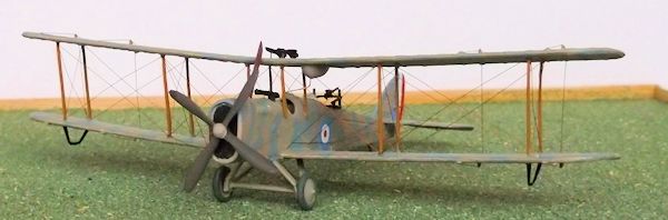 rom thin stretched sprue or rod from the fuel tank to the rear
fuselage strut and then run it to the fuselage. Fix the Vickers gun on the top
of the fuselage, wheels on to the axle, exhausts and some control horns on the
fuselage beneath the gunner's cockpit and you are ready to finish the model.
rom thin stretched sprue or rod from the fuel tank to the rear
fuselage strut and then run it to the fuselage. Fix the Vickers gun on the top
of the fuselage, wheels on to the axle, exhausts and some control horns on the
fuselage beneath the gunner's cockpit and you are ready to finish the model.
Rigging this model was
very straightforward when compared to the pushers that I have been building
recently. The wings are very easy and the tailplane and control wires presented
no problems. I use copper wire and measure each wire separately with a pair of
dividers - check each length prior to fitting and trim if necessary before
fixing with a drop of superglue. The most difficult wires were the anti-drag on
the nose as they have to match and be attached to the corner of the engine
nacelle - leave these until last. Finish the model by adding the propeller,
Lewis gun and mount and a small windscreen for the gunner.
| CONCLUSIONS |
This is a simple WW1
model - ideal for a first timer and excellent value for money. It is accurate
enough as it is presented, and provided that you make the very minor
modifications I suggest above you can produce a very good model from it with
little difficulty. It can also be easily modified if you wish. There are a large
number of paint schemes possible with this kit, although some will require some
minor modifications such as on mine, but these are easy and give useful
experience if you want to be more ambitious with later conversions or just want
something a little different. The conversion potential of this model is huge -
it is a relatively cheap source of useful parts for many projects and as such is
a conversion modeller's dream: if you are interested stock up on kits whenever
it becomes available.
| REFERENCES |
Profile
no 26: The de Haviland D. H. 4,
J. M. Bruce.
Bombers 1914 -1918,
K. Munson,
Blandford.
Airco D. H. 4,
J. M. Bruce,
Albatross Special Publication.
August 2013
Thanks to If you would like your product reviewed fairly and fairly quickly, please contact the editor or see other details in the Note to Contributors.