1/72 RAF FE 2b
| KIT #: | |
| PRICE: | $ |
| DECALS: | Spares |
| REVIEWER: | Stephen Foster |
| NOTES: | Parts came from VeeDay BE 2c, Airfix DH.4 and scratchbuilding |
| HISTORY |
Big, awkward, ungainly, flying kitchen sink, birdcage - these are some of the epithets given to the Royal Aircraft Factory FE 2b. It was an aircraft that looked old even when it was first built in 1915. In fact the FE 2b, and its contemporary the BE 2c, were highly successful machines with a better performance than almost all of the other designs emanating from private companies at that time. In consequence they were ordered by the War Office for the RFC in large numbers after the outbreak of the First World War, but two factors combined to give them unenviable reputations: the slowness of the British aero industry to produce them in sufficient quantity, and the rapid changes in aeroplane technology which rendered both designs obsolete just as substantial deliveries finally got underway. The result was that large numbers of machines were supplied to the RFC with awful consequences for the crews who had to fly them. In fact the FE 2b was able to hold its own in day operations until spring 1917, and continued in front line service as a night bomber until November 1918. It was also used as a training machine.
The FE 2b was derived from the FE 2a which was designated a "gun carrier". The original purpose of the FE 2a was armed reconnaissance, escort, and the pursuit of enemy machines. Powered by a 120hp Beardmore 6 cylinder engine, the FE 2b first flew in March 1915, but it was not until the autumn of that year that production started, and even then the order for the first 12 machines was delayed until late in the year because of the difficulties encountered in building the engines. Thus it was only in early 1916 that the RFC took delivery of machines in quantity - by May 5 squadrons were equipped. Armed with 2 x 0.303 inch Lewis machine guns these aircraft were initially used defensively and provided armed escorts for the by now obsolete BE 2c's on photo-reconnaissance and artillery co-operation duties, but pilots soon learned that it was superior to the Fokker EIII monoplane and when they started to fly offensively they helped to put a rapid end to the "Fokker scourge". In fact, so effective were the FE 2b's that, combined with DH 2's and Nieuports, they achieved aerial supremacy over the western front from July to September 1916.
 It has often been remarked that the
observer did not have a safety belt, but two things need to be remembered in
this context. Many pilots, including those in single seaters, did not have
them either until as late as 1918, and the slipstream was sufficient to hold
the observer in the cockpit except in very violent manoeuvres. when he was
expected to be holding on to a machine gun. In 1916 these aircraft were well
regarded by their crews: as one pilot wrote to his father: "…they can do
anything, such as reconnaissance or bombing, and while the Hun is faster and
more manoeuvrable, the FE 2b in the hands of a good pilot and observer is
hard to defeat. In fact, it is so solid that unless they hit the pilot or
the engine, the ship will keep afloat and limp home, often riddled with
bullets…" Even in early 1917 the Germans found that they had to treat FE
2b's with caution and unless the pilot was a von Richtofen or Almenroeder
they were not the easy targets that later myths imply. Max Immelmann was
shot down by a gunner in an FE 2b and von Richtofen was hit by a bullet from
his own side while in a melee with FE 2b's. Ltnt's K. Schaefer and A. Ulmer
were both flying Albatross fighters when they were shot down and killed by
FE gunners in 1917: the conflict was by no means one sided. 28 pilots and 20
gunners made "ace" while flying FE's, an achievement that would have not
been possible if these machines had been as inferior as sometimes made out
by later commentators.
It has often been remarked that the
observer did not have a safety belt, but two things need to be remembered in
this context. Many pilots, including those in single seaters, did not have
them either until as late as 1918, and the slipstream was sufficient to hold
the observer in the cockpit except in very violent manoeuvres. when he was
expected to be holding on to a machine gun. In 1916 these aircraft were well
regarded by their crews: as one pilot wrote to his father: "…they can do
anything, such as reconnaissance or bombing, and while the Hun is faster and
more manoeuvrable, the FE 2b in the hands of a good pilot and observer is
hard to defeat. In fact, it is so solid that unless they hit the pilot or
the engine, the ship will keep afloat and limp home, often riddled with
bullets…" Even in early 1917 the Germans found that they had to treat FE
2b's with caution and unless the pilot was a von Richtofen or Almenroeder
they were not the easy targets that later myths imply. Max Immelmann was
shot down by a gunner in an FE 2b and von Richtofen was hit by a bullet from
his own side while in a melee with FE 2b's. Ltnt's K. Schaefer and A. Ulmer
were both flying Albatross fighters when they were shot down and killed by
FE gunners in 1917: the conflict was by no means one sided. 28 pilots and 20
gunners made "ace" while flying FE's, an achievement that would have not
been possible if these machines had been as inferior as sometimes made out
by later commentators.
Early Fe 2b's had a complicated oleo tricycle undercarriage with a nose wheel to stop it overturning on take off or landing, but this was soon replaced in the field with a simpler V, and later by a simple V on production machines. Over 2000 FE 2b's were built: some were allocated to Home Defence squadrons against night attacks by Zeppelins, but the poor ceiling of the machines made them unsuited for this work.They were also used on anti-submarine patrols in NE England, but a large number were used as night bombers after they were withdrawn from day operations in the late spring of 1917. This was because there were so many available due to large early orders, and that there were no effective night fighters so they could easily perform in this role. The type was declared obsolete in early 1919.
Have you ever had the desire to build a model of a particular aircraft but have been frustrated by the fact that no kit exists in the right scale? For many years I had wanted to build an FE 2b in God's Own scale, but then I stopped modelling. Since then two excellent kits have been issued - in the wrong scales! Formaplane have issued a vacuform kit in 1/72 scale but these are rare birds and anyway I am not keen on vacuforms, so the only option left was to convert one from an existing kit of another aeroplane. Soon you will have the Airfix BE 2c which has wings and other parts which can form the basis of this project, together with some struts from card or the spares box, plastic card, florists wire, copper wire and filler. Time and patience will also be needed to complete this model. In fact you will need the wings, wheels, radiator, propellor, Lewis gun and struts from the BE 2c, some may consider using the wings and Lewis from a second kit too, as the span of the FE was greater than that of the BE 2c, and you will need two Lewis guns. The biggest problem was the engine which I had to make from scratch, but there are some excellent photos of the 120 hp Beardmore from the WNW kit on several websites which will help with the details. I also used a copy of the DataFile no 147 which has a good set of accurate plans to work from, and some good photos of a replica machine in New Zealand. As I already had form with pusher conversions this was another to add to my collection.
| CONSTRUCTION |
I started by moulding a nacelle using
30 thou plastic card and made up the details of the pilot's cockpit from
plastic card and rod. You will need a seat, control column, instrument panel
with compass, and a bulkhead to the front and rear. In the observer's
cockpit I shaped a piece of laminated plastic (two small sheets of 60 thou
card) to represent the wooden cover for the rudder bar and Lewis drum
storage. A floor from 10 thou card was made for both cockpits and bracing in
the interiors of both from thin rod or stretched sprue. I painted the
interior of the fuselage clear doped linen with light grey in the rear of
the pilot's cockpit, pale yellow for the bulkheads, instrument panel and
rudder bar cover, aluminium for the pilot's seat and light wood for the
floor. There are some superb images of the cockpit details of the Wingnut
Wings FE 2 on the net: these are worth consulting for details of fittings
and colours. Take the radiator of the DH 4 and sand off most of the surround
so that it will fit inside the fuselage halves. You need to keep checking
how much plastic to remove - make it as snug a fit as possible. It fits in
the front end of the engine bay immediately behind the bulkhead at the back
of the pilot's cockpit. Do not worry that it does not extend to the floor as
this cannot be seen. When you have completed the all the interior details
carefully cement them into one fuselage half and then join the two halves
and allow to dry. Drill a small hole just behind the pilot's cockpit and on
the port side below the engine compartment to add the radiator and petrol
filler caps. Four small discs of card should be added to the rear fuselage
to represent access ports, and drill two small holes for a step for the
pilot on the port si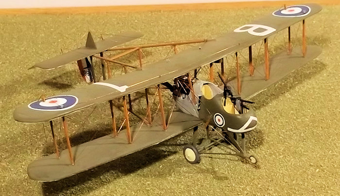 de. I made two air intakes from 10 thou card bent to a
curve, with small triangular pieces for the top and bottom.
de. I made two air intakes from 10 thou card bent to a
curve, with small triangular pieces for the top and bottom.
The engine has either to to be built from scratch or if you can find or have one from Aeroclub this can be used. If you build one from scratch I strongly recommend that you again look at pictures on the internet of the WNW kit under construction as these will give you all of the details you need. Remember that the engines varied: the 120hp engine differed from the 160hp engine in many small ways, so decide which you want to build. The cylinders were made from 80 thou rod. The sump was made from two strips of 60 thou and one of 30 thou card, and was shaped with a file and glass paper. Glue the cylinders to the sump and then add the pipes on the sides of the cylinders before painting this sub-assembly. I used a mixture of Humbrol fitting copper and dark brown for the cylinders and pipes, this takes the shine out of the metallic paint and gives it a more worn look. Now add the push rod covers on the port side (black), vents for the sump also on the port side (brass), and finally the fuel pipes and carburettors, also on the port side. On the other side you will need an exhaust pipe - I made mine from a cocktail stick and small pieces of 10 thou card for the pipe and vents and thin rod for the entry pipes. The rocker arms on the top were pieces of 15 thou card shaped and glued into place, and the magneto cover at the rear was a piece of shaped laminated card. Drill out a hole at the end of the sump for the propellor and finally make an oil tank for the port side from sprue: this is not attached to the engine but sits alongside it on the starboard side of the engine bay. Paint the details during or when you have completed the assembly. When the engine is complete place it carefully into the engine compartment to measure the size of the supports you will need to put in to the bottom of the nacelle to hold it in the correct position. The supports were made from scrap card. Paint the interior of the engine compartment and the radiator black, but do not put the engine in at this stage.
Decide whether your machine had a two or four bladed propellor. If it was a two-blader cut two blades from the BE 2c propellor and sand the boss smooth. Strictly the propellor is not quite the right shape but it is close enough not to notice. Insert a small pin just long enough to go into the hole in the engine, but again do not fix in place yet. If it is a four-blader that you want then just use the kit part.
The wing panels of the BE 2c were the same as the FE 2, except that the FE had a larger overall span. Take the wings from the BE 2c and cut out the centre section of the upper and lower wings along the line of the ribs which form the edge of the cut-out. If you are using the wings from a second BE 2c you will need to measure carefully the length of the central panel of the top wing of the FE 2 and cut this from one half of the lower wing of the BE 2c. The inner panels of the lower wings will need to be cut from the other half of the lower BE 2c wing, the strut holes are then filled. Remember to reduce the chord of the upper wing centre section by 1mm, leaving the trailing edge square. This will leave you a spare upper BE 2c wing which can be used later to make an new FE 2d wing!
If you decide to make the central
wing panels from card instead of using a second BE 2c, cut one piece of 30
thou card per wing panel, shape the edges to fit the plan and then shape to
an aerofoil section, remembering to remove some of the underside to achieve
the correct curvature. Check the profile against the BE 2c wings as you
progress so that you get as close a match as possible. On the lower wing
sections leave the final shape of the join with the fuselage until later.
When you are happy with the new inner panels carefully drill two small holes
in each wing panel checking carefully that they are opposite the ones in the
panel to be joined. I used short pieces (4 mm long) of fuse wire to
strengthen the join: these are first bent slightly and then one end glued
into the holes using superglue. Now bring a pair of panels together and
check for fit and file the joint so that you will get the correct anhedral.
When ready glue the
 panels together with cement for the plastic and
superglue for the pins and support the panel so that the correct anhedral is
achieved. Repeat this operation for the other panels, and when they are all
dry fill any gaps and sand down the joints.
panels together with cement for the plastic and
superglue for the pins and support the panel so that the correct anhedral is
achieved. Repeat this operation for the other panels, and when they are all
dry fill any gaps and sand down the joints.
Place the nacelle on a plan of the FE and take one of the bottom wings to test how it will fit to the nacelle. Lay the nacelle on the wing and mark where the wing needs to be cut and shaped: then carefully shape the joint so that the wing fits well against the nacelle side. Repeat the operation with the other wing. Make sure that the leading edges of the wings are at 90 degrees to the centre line of the nacelle and that when both wings are in place they sit properly over the plan. When you are happy with the joint cement one wing to the nacelle and support the wing while it dries so that the correct anhedral is achieved. Repeat the process for the other wing, and fill and rub down any gaps if necessary.
Mark on the top of the lower wings and nacelle the location holes for the struts and drill small holes in the wings. Drill holes on the underside of the wings for the wing skids. On the nacelle cut two small recesses for the struts behind the pilot's cockpit. Using the lower wing and nacelle holes as a guide mark on the strut location holes on the underside of the upper wing and drill these. Cut two small rectangles of 60 thou plastic card and laminate them and when dry shape it to form a new gravity tank. Glue the tank to the lower side of the upper wing and fill any gaps and rub down. Cut the fin and horizontal tail stabilizer from 20 thou and 30 thou card respectively, and shape to aerofoil section. Score the elevators on the horizontal stabilizer, and cement the fin to it. Cut a rudder from 20 thou card and shape to aerofoil section.
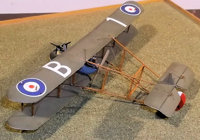
Mark on the lower wings the locations where the booms will fit: use the plans to mark the place and angle by laying the wing on the plan and then a piece of rod over the plan to represent the boom. Cut a shallow groove in the wings. Repeat the operation for the upper wings but make sure that the grooves in both wings align exactly. Cut the four booms from either brass rod, plastic rod or as in my case, florists wire. Metal booms are much stronger than plastic and I advise their use. Chamfer the ends of the rods where they will join at the tail end and cut four cross struts from card or find suitable struts in the spares box. Glue together the booms and the struts - lay the booms over the plans to get the correct alignments and strut positions.
| COLORS & MARKINGS |
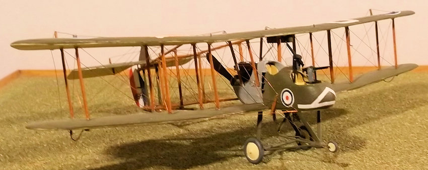
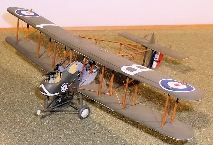
The basic colours of FE 2's were PC 10 on the upper surfaces and nacelle sides forward of the engine compartment, light grey on the engine compartment (I mixed a little silver with Humbrol Sea Grey Medium), and clear doped linen for the undersurfaces. Wheel covers could be either PC 10 or clear doped linen - check photographs or other sources. It was a fairly common practice to replace wing panels or ailerons in service so that a mix of PC 10 panels and clear doped linen panels were seen, or ailerons had part of a roundel on them even though they were on the lower wings. There are many well recorded examples of this practice if you want to present a different scheme on your model, but check the sources first. The rudder stripes and all of the cockades were hand painted: it would be possible to use the wing cockades from the DH 4 but suitable cockades for the fuselage was a problem. The serial was from dry rub-down transfers as were the white markings on the nose which were touched in with white paint. The letter and number on the top wing were hand painted. I did not put on the dedication which should appear under the pilot's cockpit because I did not have suitable small white lettering and could not paint it by hand: a minor detail which I suspect most people will not notice!
| FINAL CONSTRUCTION |
Place the engine into the engine
compartment and glue into place and allow to dry out thoroughly. The booms
can be attached to the wings at this stage. This is a tricky operation as
the angle of the booms behind the wings is critical if the "sit" of the
completed model is to look right. Support the lower wings and nacelle while
the lower booms are put into place - use CA. Fix the upper boom to the upper
wing remembering that the boom angle from the wing trailing edge is
different from that of the lower wing. Glue the rudder to the apex of the
lower boom - in order to get this to stay vertical I inserted a short pin of
plastic rod in the bottom of the rudder and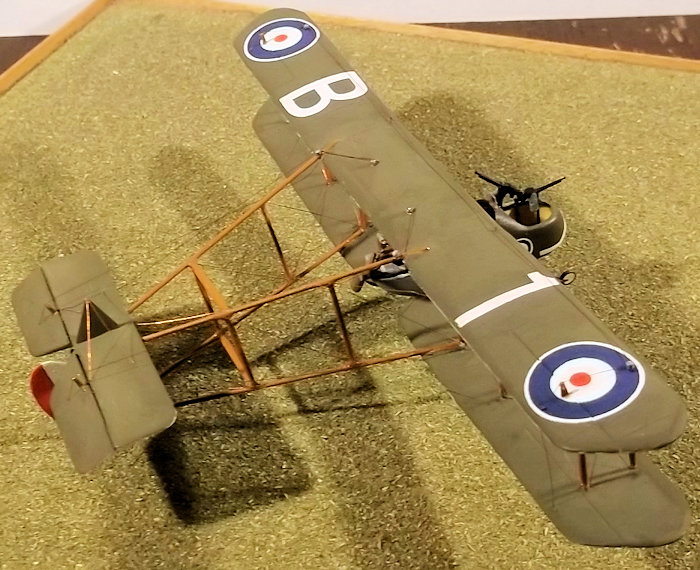 put this into place with
superglue. When I fixed the top wing and boom assembly this could rest on
the rudder and be superglued into place. Now fit the four outer struts to
the location holes in the lower wing and while they are still moveable lower
the top wing on to them and fix it in place and the rear of the booms to the
top of the rudder. This assembly will need support during this operation
until the the glue is dry. Then carefully insert the remaining wing and
cabane struts and allow these to dry. The boom struts were put in next using
struts from the spares box (I think from an Avro 504), and card for the wide
ones at the rear. All were fixed with superglue. When the whole structure is
complete it is more rigid than it looks. You may wish to use a jig to hold
things in place during this work - I managed not to do so but ensuring
everything lines properly is very important.
put this into place with
superglue. When I fixed the top wing and boom assembly this could rest on
the rudder and be superglued into place. Now fit the four outer struts to
the location holes in the lower wing and while they are still moveable lower
the top wing on to them and fix it in place and the rear of the booms to the
top of the rudder. This assembly will need support during this operation
until the the glue is dry. Then carefully insert the remaining wing and
cabane struts and allow these to dry. The boom struts were put in next using
struts from the spares box (I think from an Avro 504), and card for the wide
ones at the rear. All were fixed with superglue. When the whole structure is
complete it is more rigid than it looks. You may wish to use a jig to hold
things in place during this work - I managed not to do so but ensuring
everything lines properly is very important.
The undercarriage of the FE 2 changed over time. The original complex oleo system was modified into a V system in the field and later an even simpler V was introduced and became standard. It is important that you know which version you want to use before you start and then ensure that you have a drawing or good photographs to work from. I wanted to model the original oleo system as I think that it captures the ungainly, almost prehistoric look of this machine: others may opt for a simpler undercarriage but opt to put on bomb racks or a camera as extra detail. I cut all of the legs from 20 thou card shaped to aerofoil section. The main legs were a little longer so that I could drill holes in the ends to take the axle which was made from wire. I then assembled the undercarriage in the following sequence:
Cut small notches under the nacelle where the legs are to be located and cut small tabs on the ends of the legs to fit the notches; glue the main undercarriage legs to the nacelle and fix the axle; glue the forward legs to the nacelle and then the streamlined fairing (if required); glue the auxiliary legs to form a v between the main legs and then the arms to the axle; put in the three rods between the fairing and rear legs: put the middle one in first and then the two on the sides; allow the whole to dry out thoroughly. I fixed the front and rear legs and waited until they were nearly dry before completing the construction which is surprisingly strong.
The nose wheel was made from a disc of 20 thou card and the yoke from a piece of 10 thou card with a slot cut into it.
If you choose to model other versions of the undercarriage, including the simple V, cut the legs from plastic card and the axle either from plastic or metal rod. For all variants the wheels from the DH 4 can be used. Make a small generator and cockpit step and fit them under the nacelle: the latter is on the port side just below the pilot's cockpit.
Paint all of the struts and booms light wood and the undercarriage legs PC 10. The wheel discs were either clear doped linen or PC 10 - again check photos or artists drawings. The tail skid is simpler than it looks - mine was made from 20 thou card. I left the skid and forward and rear bracing until the model was rigged as these are delicate parts and easily damaged. Control horns were cut from card for the sides of the nacelle and control surfaces - these too are light wood in colour. Cement a small arm on the cross strut above the tail skid (black), and pulley covers for the control cables on the booms and wings from thin rod.
Rigging
 Start with the bracing wires from the
nacelle to the top wing. The control cables from the fuselage sides to the
pulleys on the lower wing and from the fuselage control horns to the top
wing undersurface are next. Then rig the wings including the control cables
between the ailerons. I also rigged the bay in the boom next to the rudder
and the horizontal bracing between the two cross bracing struts as the top
one is partially covered by the horizontal stabilizer. Now attach the tail
unit to the upper boom: note the only the leading edge rests on the booms,
the rear was supported by a moveable support to allow for variable incidence
- I represented this by a small piece of bent plastic rod. Now the booms and
tail can be rigged, followed by the control and anti-drag wires. Do not
forget the undercarriage. Finally add the last details including the tail
skid, propellor, gun mounts and guns, pilot's windscreen, nose wheel (on the
early u/c version), pitot tube and wing skids from 5 amp fuse wire painted
black to complete the model.
Start with the bracing wires from the
nacelle to the top wing. The control cables from the fuselage sides to the
pulleys on the lower wing and from the fuselage control horns to the top
wing undersurface are next. Then rig the wings including the control cables
between the ailerons. I also rigged the bay in the boom next to the rudder
and the horizontal bracing between the two cross bracing struts as the top
one is partially covered by the horizontal stabilizer. Now attach the tail
unit to the upper boom: note the only the leading edge rests on the booms,
the rear was supported by a moveable support to allow for variable incidence
- I represented this by a small piece of bent plastic rod. Now the booms and
tail can be rigged, followed by the control and anti-drag wires. Do not
forget the undercarriage. Finally add the last details including the tail
skid, propellor, gun mounts and guns, pilot's windscreen, nose wheel (on the
early u/c version), pitot tube and wing skids from 5 amp fuse wire painted
black to complete the model.
| CONCLUSIONS |
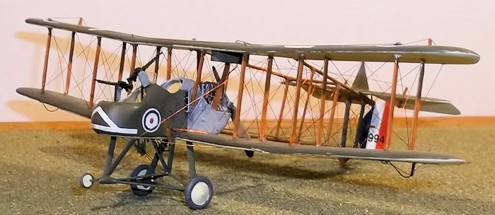
For those who are wondering how I managed to get hold of an Airfix BE 2c for this conversion, the answer is that I did not. Instead I had a Veeday BE 2c which supplied my wings, the guns, struts, propellor, wheels and other odds and ends came from an Airfix DH 4. This article assumes that you would be able to get the new Airfix kit. This was not a simple conversion and I was pleased to have had form with other pusher conversions before I attempted this one. However it was not as difficult as I had thought it might be - the most important point was to make sure all alignments were accurate, if necessary by using simple jigs. I found making and modifying parts relative straightforward: if you have conversion experience you should not have many problems either, although some of the smaller parts were a bit fiddly. Patience was the key ingredient, as it is in all good modelling. Now at last I have my FE 2b in God's Own Scale, something that I have wanted for very many years. I could have modelled a bomber variant with bomb racks and bombs but decided that I did not want to bother with these details. Some people might think that converting and rigging a pusher biplane in 1/72 scale is a task for masochists but the idea of starting with a BE 2c and ending with an FE 2b seemed like a good one to me. Why not test your modelling skills and give it a try?
| REFERENCES |
Windsock Datafile No 18: RAF FE 2b, j. J. M. Bruce, Albatross Publications, 1989.
Windsock Datafile No 147 The FE 2b at War, P. R. Hare, Albatross Publications, 2011.
Warplanes of the First World War, Fighters Vol 2, J. M. Bruce, Macdonald, 1968.
Pusher Aces of World War 1, J. Guttman, Osprey Publications, 2009.
Royal Aircraft Factory FE 2b/d & Variants in RFC, RAF, RNAS and AFS Service, Cross and Cockade, 2009.
Back to the Previews Index Page