Airfix 1/72 UH-46 Sea Knight
| KIT #: | 03051 |
| PRICE: | AUD $10.00 |
| DECALS: | Two options |
| REVIEWER: | George Oh |
| NOTES: | Basic kit that was tweaked a bit. |
| HISTORY |
Frank Piasecki pioneered helicopters with two,
overlapping, tandem rotors mounted on the front and rear ends of the fuselage
(to separate them horizontally), and rotating in synch, in opposite directions.
His design, the H.21 Shawnee, used a bent fuselage to separate the rotors
vertically which condemned it to be remembered as the ‘Flying Banana’. In 1956,
the Vertol Aircraft Corporation began developing a cleaned-up, turbine-powered
version. The result was a new, more-compact, flat-floored, straight-fuselage
design with the two counter-rotating tandem rotors atop separate pylons to
achieve the ve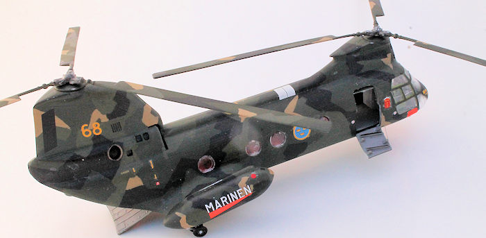 rtical and horizontal separation. Positioning the two 641kW
Lycoming T53 turboshaft engines inside the base of the rear pylon made the
inside quieter and cleared the fuselage for cargo. Loading was facilitated by a
2-piece tail ramp. A watertight, compartmentalised belly permitted water
operations. Large sponsons extending laterally from the rear fuselage further
kept the cargo area clear, gave the design a stable, wide-tracked undercarriage,
and provided easily-accessible fuel tanks.
rtical and horizontal separation. Positioning the two 641kW
Lycoming T53 turboshaft engines inside the base of the rear pylon made the
inside quieter and cleared the fuselage for cargo. Loading was facilitated by a
2-piece tail ramp. A watertight, compartmentalised belly permitted water
operations. Large sponsons extending laterally from the rear fuselage further
kept the cargo area clear, gave the design a stable, wide-tracked undercarriage,
and provided easily-accessible fuel tanks.
It was chosen in 1960, by the US Navy, as their medium-lift transport helicopter, and designated as the UH-46A Sea Knight (or, unofficially, as the Frog or Phrog). They were also used by the US Marines as the CH-46A. Other countries use the Sea Knight as the Canadian CH-113, the Swedish HPK-4, and as the KV-107/IIA by Japan, Thailand and civilian owners.
The normal military crew compliment was four. Adding up to three guns required a fifth crew member. The Sea Knight could carry 24 troopers, up to 15 stretches or up to 5,000lb of cargo. The last Sea Knights in service were US Marine ones retired in 2015 in favour of the MV-22 Osprey.
| THE KIT |
Because this kit is in my
stash, I suspect that it is an olde. It came in a standard Airfix lid-and-tray
box that held, unrestrained, the one clear and two grey sprues. Instructions
were on a double-sided A3 sheet that gave some history in ten languages, two
painting diagrams and a four-step assembly process. The two decal options were
in-register and provided some (but not 100% of the required) stencilling detail.
The cockpit is basically complete with collectives and cyclics for both crew
members (who would be staying home) and an instrument panel, but no pedals.
Detail is soft. A glaring omission from the kit w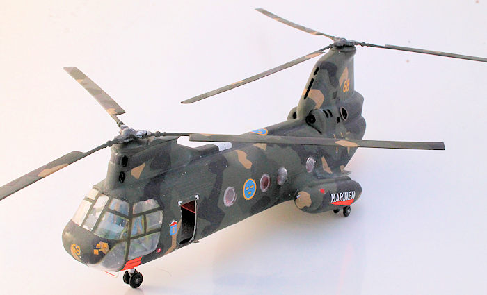 as an extension from under the
instrument panel, forward to the solid panel that is moulded as part of the
one-piece transparency. The fuselage is covered with fine raised detail and
rivets. Close examination of the parts revealed that the fit was generally
pretty good, and that some large sink-marks would have to be filled. The
fuselage’s interior cargo bay is totally devoid of any detail and connects with
the hollows of the sponsons and the pylons.
as an extension from under the
instrument panel, forward to the solid panel that is moulded as part of the
one-piece transparency. The fuselage is covered with fine raised detail and
rivets. Close examination of the parts revealed that the fit was generally
pretty good, and that some large sink-marks would have to be filled. The
fuselage’s interior cargo bay is totally devoid of any detail and connects with
the hollows of the sponsons and the pylons.
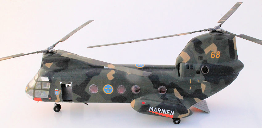
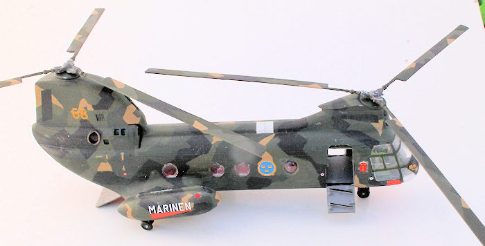
I decided to build it for an internet Helicopter Group Build. Because I like to challenge myself (and because I’d love a Swedish girlfriend) I elected to do the Swedish Navy version – besides, it has colourful markings, outriggers on the sponsons and a wilder camouflage scheme than any I’ve painted before. As per my norm, the rotors would be rotable (‘cos I like that) and removable (for ease of transport). To hide the so-so fit of the tail gates, I decided keep them movable too. But this would expose the empty interior and the hollow pylons. So, I’d have to do something about that. And because it was missing and would be visible, I resolved to build the missing forward extension (later).
| CONSTRUCTION |
As I contemplated the improvements, I assembled the cockpit. The instructions provided a printed patch to be cut-out and stick onto the instrument panel. To preserve the instructions in-tact, I photocopied it to give me the instrument panel piece. It was a bit small, but a little black and white paint fixed that. For a little colour, I scratch-built a small red fire extinguisher and a white first-aid kit for the bulkhead.
Using really-thin plastic sheet that easily conformed to the curvature of the fuselage, I covered the openings to the inside hollows. The sheets that sealed the pylons were attached to one fuselage half, and only completely sealed the pylons after I’d closed the fuselage. Ditto the thicker plate that I used to replicate the floor. Seats for the troopers were quickly made from plastic card and painted red (so that they could be seen and would distract from the crude interior). Before closing the fuselage, I drilled-out the four sockets that were to take the locating pins of the two back doors.
 With the fuselage closed
and the cockpit in-place, I could work on that forward extension. And once I
figured-out how to do it, the construction was a snap. The start was to
razor-saw into the clear front canopy along the two frames flanking the portion
to be painted solid, and the clear bit. With the cut canopy tacked in place, I
used my cuts to guide me as I also cut a little way into the cockpit floor on
both sides of the instrument panel. Pieces of thin plastic card were pushed
through the cuts in the canopy (for height and alignment reasons), and into the
cuts in the floor, where they were glued. Now I could remove the canopy, trim
the plates to match the cockpit floor, and place a piece between them to cover
the open top. Attach the cockpit canopy (fit was so-so), trim the plates to
match the outside of the solid panel and fill the gaps completed that little
job. I shoulda added pedals. With the fuselage complete, I could progress to
filling the sink marks and seams. The seams of the outriggers needed filling,
but they fitted snugly and seamlessly over the rear undercarriage sponsons.
With the fuselage closed
and the cockpit in-place, I could work on that forward extension. And once I
figured-out how to do it, the construction was a snap. The start was to
razor-saw into the clear front canopy along the two frames flanking the portion
to be painted solid, and the clear bit. With the cut canopy tacked in place, I
used my cuts to guide me as I also cut a little way into the cockpit floor on
both sides of the instrument panel. Pieces of thin plastic card were pushed
through the cuts in the canopy (for height and alignment reasons), and into the
cuts in the floor, where they were glued. Now I could remove the canopy, trim
the plates to match the cockpit floor, and place a piece between them to cover
the open top. Attach the cockpit canopy (fit was so-so), trim the plates to
match the outside of the solid panel and fill the gaps completed that little
job. I shoulda added pedals. With the fuselage complete, I could progress to
filling the sink marks and seams. The seams of the outriggers needed filling,
but they fitted snugly and seamlessly over the rear undercarriage sponsons.
Once I figured-out how to do it, those moving cargo doors were also easy. The locating pins were lopped-off from the door flanges (two per door) and the scars were drilled to accept a slim wire pin. The single pin for the upper door was inserted into the drilled hole on one fuselage side, through the two flanges of the door then (and this was the hard bit) out of the other fuselage side through the other drilled hole. Superglue the pin to the fuselage sides (without touching the door’s flanges), and I could lop-off the excess. The pin would be hidden from view by the door. The lower door was easier because there were fewer holes to line-up. The pins were poked from the inside through each flange, then out through the fuselage. Again with the superglue and the pins could be lopped-off from both the inside of the flanges and outside of the fuselage. Call me weird, but I’ve always liked moving parts (especially props and guns) on models!
The canopy was a bit of work to mask, but I used my tried-and-true method. My method is to clearly replicate the frames on the outside with narrow strips of yellow masking tape. This makes it easy to fill-in the rest with overlapping lengths of blue tape. Strip-off the yellow, and the canopy is ready for paint. The two tail gates were taped together in the closed position, the two door apertures were plugged with sponge, and all windows (I’d left them off for now) & large intakes were plugged with Krystal Kleer. Now, she was ready for painting. To save time, I dug-out the other outside bits that needed painting too.
| COLORS & MARKINGS |
The Swedish cam is a complicated splinter-cam affair made up from four colours – black, a very dark green, a not-so-dark green and a little dark tan. My attack-plan was to spray the model a very dark green (Tamiya FX-13 J.A. green – OK, so the colour police hate me) then to cut masks from the enlarged instructions so that I could spray the not-so-dark green, then the black. The dark tan I’d add with a brush. By supporting the model via the two rotor mounting sockets, I could easily spray her (and the loose outside bits) in one hit. Now I hit a snag. The first mask that I cut from the 2D instructions would NOT fit on the 3D model. So I tried to build masks by placing bits of tape directly onto the model. But this was too tedious. Rats!! So I sought another method.
Fortunately, I had to
attend a 3-day model show (Model Expo 2016 in Melb, Aust) where I traditionally
man the model-building table. Over that time, I brush-painted the black using a
chisel-edged brush and Citadel Miniatures (CM’s) chaos black. The process was
painfully slow because of the need to constantly compare the instructions with
the model, and because of all of those ziggs and zaggs. It ‘aint exact, but
looks OK because it resembles the required pattern (doesn’t it?). Ditto the
not-so-dark green using CM’s catachan green, but this time, the process was
quicker because I had reference points to l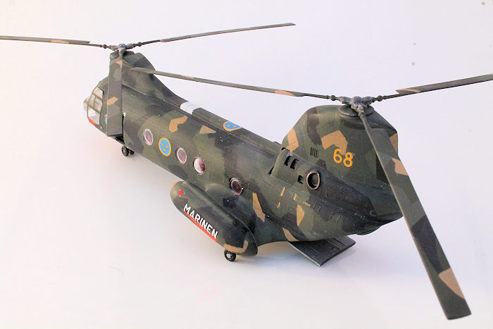 ean on – the black bits. Finally, I
spent a morning putting-on the dark tan patches using CM’s zandri dust. The
colours I chose look about right when compared with the boxart.
ean on – the black bits. Finally, I
spent a morning putting-on the dark tan patches using CM’s zandri dust. The
colours I chose look about right when compared with the boxart.
Because I ‘aint too organised, I had to spend a night adding the cam to the crew doors and on top of the rotors. A short word is needed here. The kit instructions do not specify the colours of the rotor blades. Internet research told me three things: 1) the underside of the blades are the dark green, 2) the tops of the rotors are also in 4-colour, splinter-cam, and 3) the box-art colours are too dark. Double Rats!! The paints were sealed with two coats of Future, then I hit another snag. Some of the KK that sealed apertures had spilt over from the areas they sealed. This left scars of raw plastic which needed to be retouched. Rats and double rats!!! I cheated by retouching the sprayed areas with a brush.
Rotors are the most vulnerable part of a model helicopter, so I usually make mine removable (PLUS they are rotatable). I glued the retaining boss to the underside of the rotor base plates to provide a long foundation for the rotor shaft. With much trepidation, I snipped-off the shafts from the rotor hubs and replaced them with longer brass tubes. Fortunately (for me) the rotor hubs aligned the blades to their correct orientation. Choose the blades carefully, because they ARE handed.
The Airfix decals went-on beautifully – except for the first one – the long walkway decal alongside the spine of the fuselage. As soon as it was placed on the model, it refused to be moved into position. Then it tore. My only option was to rip it off and paint it on later. It was the use of setting solutions (Microset and sol) that was the problem. Where they touched, the Future turned white, and had to be scrubbed clean with a brush, then more Future – Double Double Rats!!!! Along with the national markings, and fluro-patches, there were a lot of small decals to add as well. I hate them, but added them anyway. All decals were sealed under a coat of Future. This allowed me to put a black wash into the recesses of the various intakes and grills. Finally, she was clear flatted with Gunze H 20. This let me dry-brush the exhaust outlets.
| FINAL CONSTRUCTION |
I had to insert the windows
from the inside. This wasn’t as hard as it might seem because I was able to
access the inside through the open door and the tail gate apertures. Each in
turn was Blutacked onto the end of a bent stick, then pressed into place – then
removed for trimming of the surrounds (to clear the seats and brackets cast
inside the fuselage), then replaced, then pressed into place. They were secured
with Revell Contacta glue, applied (via that long metal tube) to the inside, and
white glue on the outside (as a sealer). The wheels were quite primitive but
usable, as were the three legs. To get all the wheels to touch the ground, I
attached one wheel to each leg, then glued each leg in position. When all wa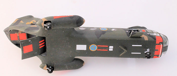 s
dry, I drilled-out the holes in the remaining wheels with a drill-bit that was a
little larger than required. Then I positioned the last wheels (the inside ones
in the case of the rear wheels). The sloppy fit, and gravity, allowed the wheels
to fall into position on the ground, and a piece of wood to ensure that they
were vertical.
s
dry, I drilled-out the holes in the remaining wheels with a drill-bit that was a
little larger than required. Then I positioned the last wheels (the inside ones
in the case of the rear wheels). The sloppy fit, and gravity, allowed the wheels
to fall into position on the ground, and a piece of wood to ensure that they
were vertical.
Internet research told me (because the instructions didn’t) that the intake bullets were to be green. Finally (or so I thought) I attached the three doors in open positions. First, strips moulded around the sides of the doorways (on-which the door pieced were supposed to lean) were scribed-off, and the edges were cut back for a thin-wall appearance. The internet told me that the large lower half of the starboard door was hinged on its lowest edge to form access stairs. A crewmember pulled it up via a rope attached to rail on the side of the door/stairs, and locked it closed. So I glued it in the lowered position, added the wire from a piece of elastic EZ-Line and ignored the absence of the rail. Another modeller’s instructions (Hi D) from another kit showed that the upper half of the door was pushed up against the inside of the fuselage roof, so I merely glued the piece in place there. I could find no information on the port-side door’s open position, so I left it off. Strip-off the masking from the canopy, and she was done.
| CONCLUSIONS |
I had three (extended to four due to a lack of participation) months in which to complete this build, and I did it in the three with about thirty hours to spare – and no pressure. As I started with the olde Airfix kit, I KNEW that it’d be a challenging build, but I’m happy that it turned-out well enough to make me happy with it (Hey – I’m the one who has to look at it on my shelf for the next few years). I’m stoked that I got the hollow areas successfully covered (without too much difficulty), and I thrilled that the mask-and-paint approach didn’t work, because the brush-paint-from-the-instructions method worked well enough to make the cam look like a Swedish job (to me).
OK – I know that there are better kits available, but this was in my stash, and I enjoyed the challenge. It looks like a Swedish Frog, so I’m happy to recommend it to all model builders whether you wish to build it OOB or push it a little.
| REFERENCES |
Just the instructions, the boxart, and Wiki blurb & images.
19 September 2016
Copyright ModelingMadness.com If you would like your product reviewed fairly and fairly quickly, please
contact
the editor
or see other details in the
Note to
Contributors.