|
KIT: |
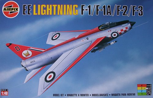
Airfix 1/48 EE. Lightning F.3 |
|
KIT # |
9179 |
|
PRICE: |
$50.00 AUD |
|
DECALS: |
five options |
|
REVIEWER: |
Grenville Davies |
|
NOTES: |
One of the most eagerly awaited aircraft in 1/48 scale and represented a new and up to date moulding from Airfix. The initial batches of this kit suffered from sink marks in prominent positions and this kit was no exception. Later production kits were better, but the wings were warped around the tips of the upper half. The decal sheet was out of register for much of the lettering. |
|
HISTORY |
The English Electric Lightning was born into an era where a fighter aircraft was marked by its speed, acceleration and rate of climb. It carved a place in history by being the first and last all British built fighter to exceed Mach 2. Its performance was breathtaking and was matched by its ability to guzzle fuel at an astonishing rate, so much so that it required tankers to be present after a very scant time indeed! It became the backbone of the UK defence during the Cold War and was generally agreed to be the best fighter in the world when it entered service. It took a very special fighter pilot to be accepted into a Lightning squadron and these pilots were generally accepted as being the elite of the RAF.
During May 1947, W.E.W. ‘Teddy’ Petter won English Electric a study contract for a Mach 1.5 – capable research aircraft to meet the British Government Ministry of Supply (MOS) specification Experimental Requirement (ER.) 103. By December 1948, this aircraft resembled the eventual Lightning, with its sharply swept untapered wings, low-set tailplane, pitot intake and staggered twin engines, mounted on top of each other. The Ministry of Supply was suitably impressed and in early 1949 signed a contract for two prototypes to be built to meet requirement F.23/49, which was to “investigate the practicality of supersonic speed for military aircraft”. English Electric had designed the P.1 as a research vehicle, albeit one that had provision for guns and a sighting system plus the ability to handle plus 7-g load limits!
 Despite the MOS being
impressed by the P.1, the Royal Aircraft Establishment (RAE) was
typically unimpressed. The RAE did not believe that Petter had got his
calculations and his air tunnel tests correct and certainly did not like
the futuristic swept wings and low tailplane configuration! They decided
to commission the Short SB.5 to prove the ‘superiority’ of their favoured
T-tail and lower leading edge sweep configuration. This aircraft was
built for pure research and had wings that could be swept at 50, 60 and
69 degrees with two settings for the tailplane, one low and one high on
the tailfin. During this time English Electric believed they had a winner
and continued with the original configuration (60 degree sweep, low
tailplane) and this was eventually proven to be superior to all other
settings. The RAE had almost ballsed up the whole program through its
ineptitude, something that was all too common within the government ranks
concerning British aviation.
Despite the MOS being
impressed by the P.1, the Royal Aircraft Establishment (RAE) was
typically unimpressed. The RAE did not believe that Petter had got his
calculations and his air tunnel tests correct and certainly did not like
the futuristic swept wings and low tailplane configuration! They decided
to commission the Short SB.5 to prove the ‘superiority’ of their favoured
T-tail and lower leading edge sweep configuration. This aircraft was
built for pure research and had wings that could be swept at 50, 60 and
69 degrees with two settings for the tailplane, one low and one high on
the tailfin. During this time English Electric believed they had a winner
and continued with the original configuration (60 degree sweep, low
tailplane) and this was eventually proven to be superior to all other
settings. The RAE had almost ballsed up the whole program through its
ineptitude, something that was all too common within the government ranks
concerning British aviation.
After the RAE had relented and given the thumbs up on Petter’s design the P.1 was trucked to Boscombe Down where it underwent its maiden flight on August 4, 1954. It was a resounding success that needed to be, given the mind-numbing decisions soon to take place. This success was as a result of the original design of the P.1, which had been finalised in 1949, being a far bolder concept than the then development of either the Russian MiG 19 or the American F-100, and this factor helped the final production Lightning to remain viable, in spite of its long gestation!
The original ER. 103 called for a maximum level speed of Mach 1.2, which was attained with non-afterburning Sapphire engines. It was realised, that, with more powerful engines, speeds in excess of Mach 2 were achievable. To achieve this level of performance it would be necessary to add a variable intake and a variable afterburner nozzle, preferably of the convergent/divergent type. The aircraft would also require a much larger fin for adequate longitudinal speed at Mach 2. The decision to produce a fighter version resulted in the research aircraft P.1 becoming the P.1A and the fighter version became the P.1B.
Three P.1B prototypes were ordered, to be equipped with the new AI.23 radar and armed with two 30mm ADEN cannons, 48 2-inch rockets and two deHavilland Propellers Blue Jay IR homing AAMs. The aircraft was envisioned as being a short range point interceptor, with no collision course intercept capability and no long range role. It was becoming fanciful to think that the pilot was becoming redundant! In Britain most still believed that a night / all-weather interceptor required a back seat driver, and it took years to convince a very staid Air Staff that the P.1B would be admirably suited to the night / all-weather role.
 The P.1A was continuing in
its role as a research aircraft with the second airframe being flown on
18 July 1955, fitted with a neat ventral fuel tank and plain flaps on the
trailing edge instead of the original split flaps. In January 1957 the
first P.1A flew with a revised wing that had a reduced sweep outboard and
a slight camber on the leading edge. This configuration was found to
increase lift at much higher angles of attack whilst reducing drag and
buffeting, but was judged to be too costly to be incorporated in the
P.1B. It would take many years before it was finally adopted in the
ultimate Lightning, the F Mk. 6!
The P.1A was continuing in
its role as a research aircraft with the second airframe being flown on
18 July 1955, fitted with a neat ventral fuel tank and plain flaps on the
trailing edge instead of the original split flaps. In January 1957 the
first P.1A flew with a revised wing that had a reduced sweep outboard and
a slight camber on the leading edge. This configuration was found to
increase lift at much higher angles of attack whilst reducing drag and
buffeting, but was judged to be too costly to be incorporated in the
P.1B. It would take many years before it was finally adopted in the
ultimate Lightning, the F Mk. 6!
The P.1B made its maiden flight on 4 April 1957 on the very day that the then Conservative British Government published Duncan Sandy’s White Paper entitled “Defence – An Outline of Future Policy”. This greatly overrated piece of mindless drivel heralded the imminent replacement of virtually all manned aircraft by missiles and contained the mind bogglingly stupid statement “In view of the good progress already made, the Government have come to the conclusion that the RAF are unlikely to have a requirement for fighter aircraft of types more advanced than the supersonic P.1, and work on such projects will stop!” In the face of all things happening around the globe the British Government was about to repeat recent history and bury its collective head in the sand and, what was even more amazing was that the Air Staff, bearing a close resemblance to a corpse with rigor mortis, would let them do it in typical fashion. The White Paper was only a document of “intention” and not something dictating policy, but the Government made it a reality and cancelled some of the most challenging and thought provoking projects then being undertaken, the TSR 1 comes to mind! This single act of mindlessness resulted in the British Aircraft industry sliding from being one of the best in the world to an also ran. The only saving grace in this fiasco was that the P.1 was allowed to survive not because it was worthy, but simply because it had ‘gone too far in its development to be cancelled’!
Many felt that the aircraft would only be required for a short time at best and it would ultimately be replaced by the wonderful, futuristic missiles by 1964. History has shown us that this did not happen but it left little incentive for further development work to be carried out and the aircraft’s future was very cloudy indeed. During October of 1957 the Chief of Air Staff, Sir Dermot Boyle, formally named the aircraft “Lightning”, at least saving it from being lumbered with the speculated name of “Excalibur”.
 The F.1 Lightning came into
being when XM135 became the first full production model on 25 May 1960
(it also was the last F.1 flying being withdrawn from service on 20
November 1974), replacing one of the pre production Lightning XG334,
which had the dubious distinction of being abandoned in flight after
catastrophic hydraulic failure. This model was quickly replaced by the
F.1A with the addition of a UHF radio and an in-flight refuelling probe.
The next variant, the F.2, differed little externally except with the
inclusion of an intake duct along the spine of the aircraft. The F.2A was
externally quite different from the F.2 possessing a square topped fin
and rudder, this being retained for all future variants. In addition the
wings had a cranked appearance and a larger belly fuel tank was
installed. The first of these aircraft were delivered to No 19 Squadron
on 15 January 1968.
The F.1 Lightning came into
being when XM135 became the first full production model on 25 May 1960
(it also was the last F.1 flying being withdrawn from service on 20
November 1974), replacing one of the pre production Lightning XG334,
which had the dubious distinction of being abandoned in flight after
catastrophic hydraulic failure. This model was quickly replaced by the
F.1A with the addition of a UHF radio and an in-flight refuelling probe.
The next variant, the F.2, differed little externally except with the
inclusion of an intake duct along the spine of the aircraft. The F.2A was
externally quite different from the F.2 possessing a square topped fin
and rudder, this being retained for all future variants. In addition the
wings had a cranked appearance and a larger belly fuel tank was
installed. The first of these aircraft were delivered to No 19 Squadron
on 15 January 1968.
The next generation of the Lightning was the F.3 and the subject of this review. It was powered by two Avon series engines with uprated thrust of 13,500lbs each, boosted to 16,360 lbs by reheat, which was more than twice the thrust of the original English Electric P.1. A number of changes were made for this variant especially in the area of weapons. De Havilland had been working on a replacement for the Firestreak air-to-air missile and this was to become the Red Top missile. It differed from the Firestreak by being able to be fired in head on situations as well as chase scenarios. The other major difference was the omission of the two Aden 30mm cannon mounted in the nose. Thus the F.3 was not really close combat capable. This was amended but not until the ultimate Lightning, the F.6 was in production.
A few other minor changes were made to the airframe with the fin area being increased by 15% to compensate for the larger missiles, and an extension to the fuselage side ducts.
|
THE KIT |
The box art depicts an early F.1A Lightning blasting across the skies and is guaranteed to make anyone who is into early British jets have a mild shiver with delight and cause a hasty hand to be put into the pockets to part with the cash to purchase this fine aircraft. No? Well it certainly did with me; although I was a little disappointed with certain aspects of the kit, for the most part it has been a labour of love.
 The plastic is a light grey
and relatively soft and comes on five sprues, with one clear sprue that
has the canopy parts and lenses for the various bits around the airframe,
namely navigation and landing lights. There is one humungous decal sheet
to cater for the six aircraft depicted in this kit, along with a very
comprehensive instruction booklet. All of this is packaged in a not quite
so sturdy cardboard box depicting the aforementioned early F.1A, XM174
from 56 Squadron, based at RAF Wattisham during 1963.
The plastic is a light grey
and relatively soft and comes on five sprues, with one clear sprue that
has the canopy parts and lenses for the various bits around the airframe,
namely navigation and landing lights. There is one humungous decal sheet
to cater for the six aircraft depicted in this kit, along with a very
comprehensive instruction booklet. All of this is packaged in a not quite
so sturdy cardboard box depicting the aforementioned early F.1A, XM174
from 56 Squadron, based at RAF Wattisham during 1963.
On closer inspection of the sprues some prominent sink marks were found on the upper wing surfaces as well as the gear doors. There were also some ejector pin marks in these areas but they were fairly easy to remove. The clear parts are almost distortion free. There was little flash on my example.
As this kit caters for four different aircraft variants there are a number of superfluous parts, depending on the model chosen. At the end of building this kit you will end up with spares and, in my case, as I was using aftermarket bits there would be more spares than usual! I had purchased the Cutting Edge (Kit No.: 48118) BAC Lightning cockpit set, the AeroClub white metal undercarriage set (Kit No.: ABV 167), and nose weight (Kit No.: ABV 169). The latter replaces the kit intake cone and the nose weight sits inside the cone assembly. I also purchased the Eduard photo-etch set for this particular kit (No.: 48-251).
Now it was time to assemble the thing!
|
CONSTRUCTION |
Unlike most aircraft models that I build, usually starting with the cockpit (doesn’t everyone?), I actually started to assemble the larger parts first and this meant the wings. It was necessary to install the photo-etch for the main gear wells and attach the wing leading edges. There are two options for the leading edges included as Airfix have made two kits to cater for the range of single seat fighter aircraft. In this kit the variants use the straight wing and the spare “bent wing” leading edges are not used. It was at this point in construction that the lower wing half was noted to have a distinct warp, probably as a result of using a fairly soft polystyrene. This is true of all the kits I have seen for this aircraft, including the F.6 kit. It meant that the offending piece required some careful bending back to the original shape prior to gluing the top and bottom halves. There is a sink mark on both upper wing halves immediately forward of the aileron that also needed filler, in this case it was with Squadron white filler. This is the first time that I have used this product and can only advise people to give a try. I have used it on the seams as well as the sink marks and, in conjunction with acetone-based nail polish remover, it is absolutely marvellous. It is especially useful when used on the wing to fuselage join, where it can be extremely difficult to clean up the excess filler. Using the method of applying the putty with a spatula and then using a cotton bud soaked in acetone to remove the excess, you end up with minimal sanding and hence less detail being lost. I must thank Tom Cleaver for his advice in using Mr Surfacer on the seams. Again, this is the first time that I have used this product and I am very impressed with both the 500 and 1000 grit products.
 Construction commenced on
the intake and exhaust sub assemblies and also the intake shock cone,
into which was installed the AeroClub white metal nose weight -
this is a tricycle undercarriage and potential tail-sitter after all! The
nose cone assembly is also the front wheel well and has a seam on the
inside that is not all that easy to remove – best to cover it up with
something thick and gluggy! Whilst all these bits were curing I started
to clean up the white metal undercarriage legs. These parts are very neat
and add sufficient weight to help balance the model. AeroClub make
a white metal nose ring that is a direct replacement for the kit part. I
had purchased this part for the model thinking that the extra weight
would be useful, however the fit and clean up requires more work than
sorting out the kit part so the metal nose ring was shelved and out came
the Bare Metal Foil! The white metal rings has some nasty pitting
and will require work to get it to look presentable.
Construction commenced on
the intake and exhaust sub assemblies and also the intake shock cone,
into which was installed the AeroClub white metal nose weight -
this is a tricycle undercarriage and potential tail-sitter after all! The
nose cone assembly is also the front wheel well and has a seam on the
inside that is not all that easy to remove – best to cover it up with
something thick and gluggy! Whilst all these bits were curing I started
to clean up the white metal undercarriage legs. These parts are very neat
and add sufficient weight to help balance the model. AeroClub make
a white metal nose ring that is a direct replacement for the kit part. I
had purchased this part for the model thinking that the extra weight
would be useful, however the fit and clean up requires more work than
sorting out the kit part so the metal nose ring was shelved and out came
the Bare Metal Foil! The white metal rings has some nasty pitting
and will require work to get it to look presentable.
The air brakes are represented as separate parts that may be depicted open. As there are very few shots of aircraft in this pose I decided to leave them closed. This requires some sanding of the inner surface as they don’t fit quite flush to the airframe. In addition the external piping that sits on the lower edge of each fuselage side was also attached. Care needs to be taken to ensure that only the holes required are opened up using a pin vise, as each variant uses different piping. Murphy’s Law is alive and well - I was leafing through one of my references that specifically mentioned that the piping on the F.3 is 11.5mm too forward and, although I am not usually given to going to the nth degree, this would be quite noticeable once the decals were attached to the aircraft. I set about correcting this error by removing the offending four parts, successfully destroying all but one in the process. I ended up scavenging the two forward pieces from an unbuilt F.6 kit and used half round Evergreen plastic rod for the rear pieces. Some filing was necessary to get the two profiles to match and then the half round rod was scribed in the appropriate locations. The morale of the story? Read all of your available reference material first. Normally this would not have been an issue but, just like the author of the modelling article in Scale Aircraft Modelling Volume 22 Number 5, Fred Martin, I would have found the error when I had almost completed the build – too late! To Fred, a very big thanks!
As a precursor to painting the model the undercarriage wheel wells were sprayed with a grey acrylic primer in preparation for spraying with Alclad II, Aluminium. This was the case for most of the fuselage but more on that later.
Cockpit Construction
It was now time to look at
assembling the Cutting Edge cockpit. After separating the cockpit
from the casting block it was sprayed with Gunze Sangyo Medium Sea Grey.
Later model Lightnings were painted in this colour, as opposed to black
for the earlier models, and as I was building an F.3 built during 1964 it
was appropriate. The side consoles were painted with Tamiya XF1, Flat
Black and knobs and throttle controls were painted in white, yellow, red
and silver. The instrument panel
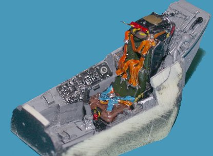 was also sprayed in the Medium Sea Grey
with relevant switches and dials being painted black. I used the
Eduard rudder pedals and the forward cockpit floor that required
trimming to fit around the resin cockpit tub. The whole assembly was then
given a wash with water colours to pick pout detail and impart a worn
look.
was also sprayed in the Medium Sea Grey
with relevant switches and dials being painted black. I used the
Eduard rudder pedals and the forward cockpit floor that required
trimming to fit around the resin cockpit tub. The whole assembly was then
given a wash with water colours to pick pout detail and impart a worn
look.
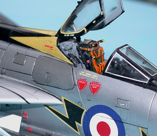
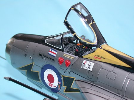
The ejector seat is very well done in this resin set and was sprayed in Flat Black. Information suggests that the seat was either all semi gloss black or had the lower portion painted grey. I used a stiff brush to impart a slight sheen to the paint, highlighted the detail with a dry brush of Medium Sea Grey and finally dry brushed some Aluminium to simulate areas of high wear. This worked quite well as can be seen in the photograph. I painted the seat back pad in Khaki Green and the squab was painted with a couple of shades of brown to simulate the leather look of my photo references. The seat belt harnesses were first painted white and then painted with Tamiya Clear Orange and Clear Blue, the latter being used for the lower parts of the harness. As both of these colours are gloss I covered them with Gunze Sangyo Clear Flat, which has given them a semi gloss appearance, although I still think that they are too shiny and definitely the orange is too red! The buckles were painted with Silver. Once everything was dry it was then given a black wash using water colours to help pick out the details and to further subdue the brighter colours used on the harness. In retrospect the upper harness should have been painted with something a little less garish, perhaps more yellow-orange!
Intake and Shock Cone Construction
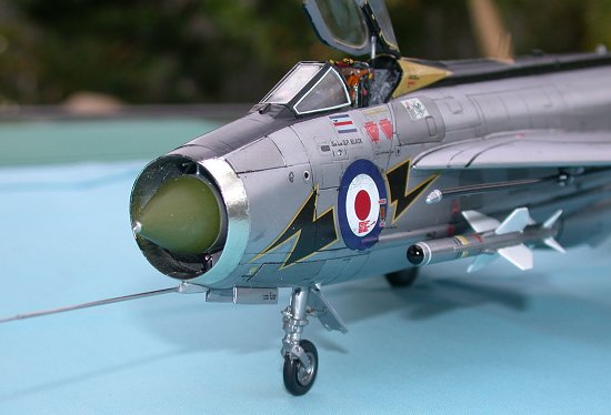
The intake for this aircraft sits directly under the cockpit and is presented as two halves that have only the lower Avon engine turbine visible. This sits on a rear panel and was painted with Alclad II Aluminium, after undercoating with grey primer, as was the intakes and the shock cone. The engine turbine spinner was painted with ModelMaster Chrome Silver.
The shock cone sits at the front of the intake and had the AeroClub
nose weight inserted prior to gluing the two halves together. This was
cleaned prior to attaching to the assembly. Test fitting of this part
into the intake, which also has the nose wheel well moulded in, I found
upon insertion into the intake that a distinct gap on the sides of the
wheel well existed. My references didn’t show this gap so I assume that
it shouldn’t be there! To correct this little error requires careful
spreading of the upper part of the wheel well just enough to make the
sides coincident with the lower well moulded into the intake. I still
ended up with a small gap that was duly filled with gap filling
superglue. The area was then painted to cover my surgery. The sensor
probe at the top of the intake trunk was replaced by a diabetic
hypodermic needle and the camera
 port on the lower intake trunk was
fitted with a MV lens. I also used two grades of hypodermic needles (18g
and 21g) to replace the pitot head boom at the base of the intake ring. I
must thank Roger Jackson for his use of such needles mentioned throughout
his reviews. They are definitely more robust than the original bits!
port on the lower intake trunk was
fitted with a MV lens. I also used two grades of hypodermic needles (18g
and 21g) to replace the pitot head boom at the base of the intake ring. I
must thank Roger Jackson for his use of such needles mentioned throughout
his reviews. They are definitely more robust than the original bits!
Once this assembly had dried the shock cone was painted with Model Master enamel, Interior Green and glued into the fuselage. Note that the very tip of the shock cone is silver and, as the part was white metal, I simply polished the end, removing the previously painted surface.
The completed cockpit was glued into the right side of the fuselage above the intake trunk after many dry fitting sessions to remove the excess resin from the bottom and front sides of the casting. The right sidewall panel was treated in a similar manner. The rear jet pipes were glued into the right fuselage half by temporarily attaching the exhaust pipes to ensure correct placement. These pipes were painted with Alclad II Jet Exhaust. Once the three sub assemblies were dry the left hand fuselage half was glued to the right using superglue. Care must be taken here to ensure a reasonable join is obtained, it will inevitably need sanding but this can be kept to a minimum with some caution. Also, if you are using superglue and it squeezes out of the join, you will need to sand it sooner rather than later or spend an age trying to remove the stuff! Once the fuselage had dried I set about filling those gaps not quite seated correctly and then sanding and re-scribing those panel lines damaged in the process in preparation for painting.
Wings and Undercarriage Construction
 With the wings being assembled in the early stages of construction a
little work was still required in the form of adding the mounting
brackets for the AeroClub wheel struts. The flaps were to be
depicted in the lowered state and as such there would be a gap in the
wing where the flaps would sit. This was filled with Squadron
white putty and sanded prior to attaching the flaps. These were added
before the wing was attached to the fuselage as it would have been a
fiddly operation afterwards.
With the wings being assembled in the early stages of construction a
little work was still required in the form of adding the mounting
brackets for the AeroClub wheel struts. The flaps were to be
depicted in the lowered state and as such there would be a gap in the
wing where the flaps would sit. This was filled with Squadron
white putty and sanded prior to attaching the flaps. These were added
before the wing was attached to the fuselage as it would have been a
fiddly operation afterwards.
The wings were then attached to the fuselage using super glue and Squadron putty to fill the join, once it was stable enough. This join was cleaned up with acetone as described above, before the putty had cured. The model was then put aside to allow the joins time to cure. One of the wings seemed to be doomed to fall off a few times before I eventually managed to get it to stay put. The model even managed to throw itself off the workbench resulting in yet another “wing fixing” attempt.
The kit undercarriage was substituted with the AeroClub kit. Clean up was essential and it was necessary to file one of the contact points on the main gear leg for the support activator. Be wary when using this kit as no instructions are provided, basically because the parts are a straight substitution for the kit offerings. Two pieces are supplied that are the mounts for the main gear struts and fit into the wheel well. They are the locators for both support and actuator struts for the main undercarriage leg. The white metal part has two bumps on it, one triangular and one circular, the latter goes to the centre of the well and is the attachment point for the smaller of the two support rods. All parts were painted with Tamiya XF16, Flat Aluminium and the oleos were scraped with a blade until shiny. A thin piece of copper wire was attached down the side of the strut for the brake lines and more wire used for the hydraulic hoses within the wheel well. The interior of the well was painted with Alclad II Aluminium.
The front wheel strut is in one piece and has only one the shimmy damper and centring unit to be attached before installing it into the wheel well. It is necessary to drill a small hole in the forks of the front wheel strut to accept a small rod that replaces the kit part that would otherwise go through the wheel. A small brass rod was used to simulate this wheel axle.
The undercarriage doors were painted on the sprue and had their decals attached prior to attaching them to the fuselage. I also used an MV lens on each of the main undercarriage doors in place of the kit lights. Similarly decals were added to these parts, where required, prior to attaching them to the aircraft.
|
COLORS AND MARKINGS |
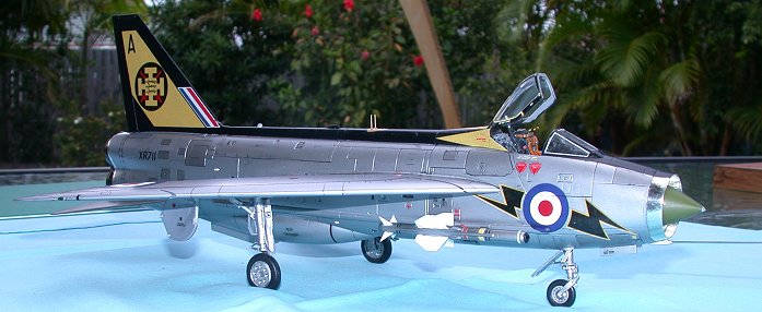
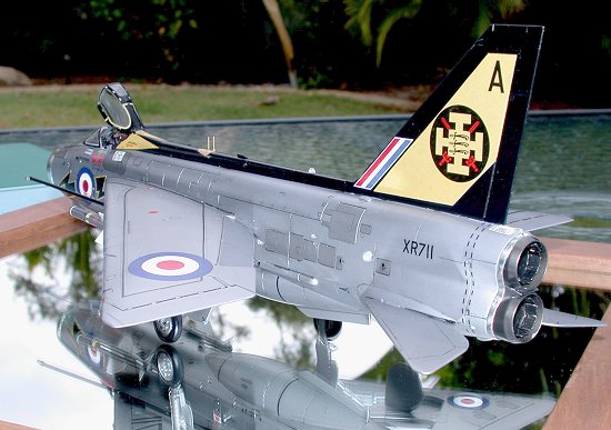
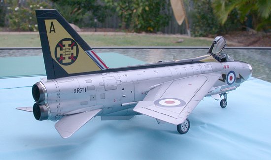
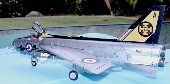
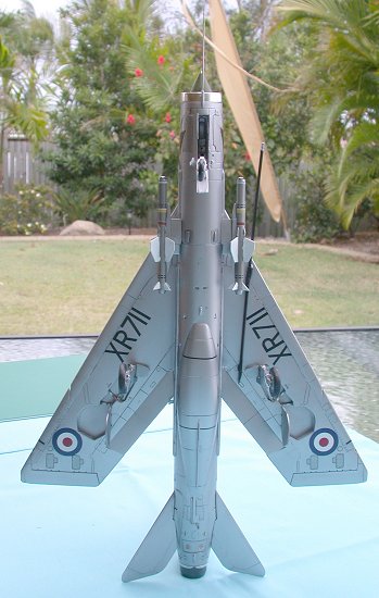
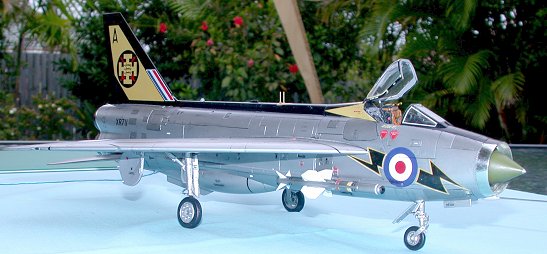
The aircraft that I had elected to build from the kit options was the F.3 from Treble One Squadron, XR-711. This aircraft was all natural metal (as are all versions in this kit), and had a black spine and tailfin with a yellow design behind the cockpit and a yellow flash parallel to the leading edge of the tailfin. It had the squadron badge on a black circle that displays the Cross of Palestine, which was the main area of operations for the squadron during WWI. Superimposed on the cross are three Seaxes that represent the County of Essex (where the squadron was based for some of the early war and between wars) and two red crossed swords to represent London, the city which it defended. The colour scheme chosen was used from 1964 onwards, until the Ministry decided that things were getting too bright and ordered units to tone down their aircraft. This particular aircraft was taken on charge on 2 December 1964. It was lost at Wattisham on 29 October 1971 as a result of dropping onto the runway just after take-off. The pilot, Flt Lt. Steenson, was uninjured but the aircraft was removed to the fire dump. It had flown for 1,667 hours and 25 minutes. (This information is from the BAC Lightning Site http://www.lightning.org.uk/ specifically dealing with the F.3. The site is well worth the look for anything you “needed to know but were afraid to ask”!).
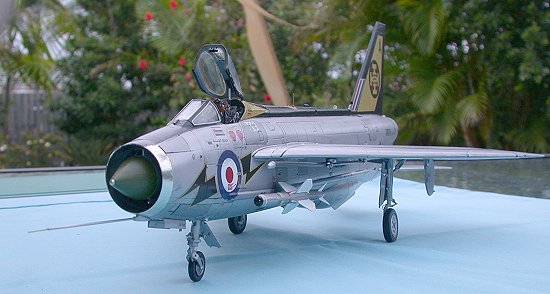 Alclad II
metal paints were used to paint the fuselage and wings and this required
the surface to be undercoated with a suitable paint. I find an automotive
grey primer suitable for the job as it is very fine and only requires a
light sanding and dust off prior to spraying the metal colour, which in
this case was Aluminium. I used a slightly different shade on a few
panels to break up the monotony and these were Dark Aluminium and
Magnesium. Once this had dried I masked off the spine, tailfin and
cockpit area and sprayed these with Tamiya TS29, Semi Gloss Black.
Alclad II
metal paints were used to paint the fuselage and wings and this required
the surface to be undercoated with a suitable paint. I find an automotive
grey primer suitable for the job as it is very fine and only requires a
light sanding and dust off prior to spraying the metal colour, which in
this case was Aluminium. I used a slightly different shade on a few
panels to break up the monotony and these were Dark Aluminium and
Magnesium. Once this had dried I masked off the spine, tailfin and
cockpit area and sprayed these with Tamiya TS29, Semi Gloss Black.
The canopy was masked using Black Magic masks and both the inside and outside surfaces were painted. The inner surface was painted with a light grey, although black is suggested, and the exterior was painted with the Semi Gloss Black. Before painting the outside some clear lacquer was applied across the mask and surface to be painted to minimise the potential for the black to bleed under the masks. This proved to be very successful. In addition a very thin strip of white decal was added to the forward canopy to simulate the glass sealant.
Having purchased a set of AeroMaster decals for Early Lightnings that I intended to use for a F.1 Lightning but eventually deciding on the F.3, I only used the roundels supplied with this decal set and all other decals came from the kit. Some of these are out of register, especially the lettering around the cockpit and the ‘lightning bolts’. Some of the missile decals were also out of register. For the most part the decals went on well and required a little Microscale Decal Set to help them settle. No silvering occurred and only on the most complex surfaces was Microscale Decal Solvent used, specifically the fuselage roundels where they overlap the fuselage piping. A small amount of blue paint was applied after the decal had cracked once it had dried.
The wheels were masked off using the aforementioned Black Magic masks, although these do seem to like the Alclad II paint really well, sticking to it like glue and pulling it straight off the undercoat! Bugger! It was back to hand brushing some Flat Aluminium on the main undercarriage.
Once all the painting had been completed the aircraft was given a coat of semi gloss clear spray to seal the decals. The last task was to add the little ‘fiddly’ bits that always seem to get knocked off during the construction phase, little things such as aerials, pitot tubes, undercarriage doors and all other doodads.
|
CONCLUSIONS |
This is a great kit to build
and even though it has taken me a few weeks longer than normal, mainly
due to self-inflicted errors, I have enjoyed the build. It is a
relatively straight forward kit to build out of the box; with due care
being paid to avoid errors of course, but OOB to me means other boxes
(just like fellow modeller Ray Snazel!). The extra money spent on the
nose weight and the cockpit detail set was well worth it, and the
inclusion of the photo etch parts and the wheel struts made life easier.
Would the kit have been as satisfying without these parts? Most
definitely, perhaps not as accurate, but it would have gone together
quicker! The pundits have generally forgone this kit and perhaps have
written it off as not being
 in the same category as the Tamigawa kits of
the last decade or so and perhaps it was this that caused the kit to not
do as well as Airfix would have liked. (Editor's Note: the Lightning
has been one of the best selling kits Airfix has ever produced. I've
heard that it paid for itself in less than two years, a phenomenal rate
for any model, but it wasn't enough for the bean counters and until the
new 1/48 Hawk [which may be an Italeri mold], was the last complete
aircraft new kit that Airfix has produced) For me it is the only game in town
in 1/48 scale and is of a subject that has been seared into the minds of
most aviation enthusiasts around the world. This aircraft can still hold
its own with some of the more modern fighter jets and can still enthral
audiences at air shows with its high speed taxi runs. If you’re really
lucky and have the cash to spare, you can even get to ride in one,
although it will mean a trip to South Africa! I have not yet been so
fortunate as to get “up close and personal” with one of these
fuel-guzzling, rocket ships of the cold war, but look forward to that
moment with great anticipation, sweaty palms and my trusty digital
camera.
in the same category as the Tamigawa kits of
the last decade or so and perhaps it was this that caused the kit to not
do as well as Airfix would have liked. (Editor's Note: the Lightning
has been one of the best selling kits Airfix has ever produced. I've
heard that it paid for itself in less than two years, a phenomenal rate
for any model, but it wasn't enough for the bean counters and until the
new 1/48 Hawk [which may be an Italeri mold], was the last complete
aircraft new kit that Airfix has produced) For me it is the only game in town
in 1/48 scale and is of a subject that has been seared into the minds of
most aviation enthusiasts around the world. This aircraft can still hold
its own with some of the more modern fighter jets and can still enthral
audiences at air shows with its high speed taxi runs. If you’re really
lucky and have the cash to spare, you can even get to ride in one,
although it will mean a trip to South Africa! I have not yet been so
fortunate as to get “up close and personal” with one of these
fuel-guzzling, rocket ships of the cold war, but look forward to that
moment with great anticipation, sweaty palms and my trusty digital
camera.
The all natural metal finish, plus the striking colour scheme of Treble One Squadron make this an excellent subject for a model of an aircraft that, not only survived the insanity of the British Government but went on to become a vital part of the Cold War. It will live on in my display cabinet as testimony to a different time when young men vied for the right to be one of the elite and fly one of these sprinters of the sky!
December 2003
|
REFERENCES |
British Aircraft Corporation Lightning, Hall, A. W., Warpaint Series Number 14, Hall Park Books Publishers, ISSN 1363-0369
BAC Lightning Site http://www.lightning.org.uk/ (specifically dealing with the F.3)
EE (BAC) Lightning - Part 1/2/3, Martin, F., Scale Aircraft Modelling Volume 22 No. 3/4/5, 2000, ISSN 0956-1420
English Electric Lightning, Lake, J., Wings of Fame Volume 7, Aerospace Publishing Ltd., 1997 ISBN 1-874023-97-2
The Lightning F.2A / F.6, Caruana, R., Scale Aviation Modeller International, Volume 4 Issue 2, 1998,
The English Electric Lightning: A Comprehensive Guide for the Modeller, Caruana, R., Modellers Datafile No. 7, SAM Publications, 2003 ISBN 0-9533465-7-9
If you would like your product reviewed fairly and quickly by a site that has over 200,000 visitors a month, please contact me or see other details in the Note to Contributors.