AMT 1/72 XB-70 Valkyrie
| KIT #: | ? |
| PRICE: | $Long out of Production |
| DECALS: | One option |
| REVIEWER: | Joel Hamm |
| NOTES: |
| HISTORY |
This build started out as an I’m Bored, Let’s Do Something Different project. It backfired completely. Not long into the kit I had to daily force myself into a plodding hour or two in the Secret Model Airplane Building Room. Not because there’s anything wrong with the model, other than a few fixable fit and engineering issues. It’s just big. Big sort of negates the eentsey-beentsey attraction of modeling (no offense to you 1/32nd folks). Big also means that the little niggling jobs like filling and sanding become BIG niggling jobs. It often seemed as if I was getting nowhere. Getting nowhere is not a good way to rise up out of the model building blahs.
I make no pretense at being an airplane historian. All I know is what I read on the WWW, some of which is occasionally believable. This summary of the XB-70’s unhappy existence was squeezed from the first few sites that popped up when I Googled the subject. Google! Who would have known ten years back that To Google would be a respectable English infinitive? Anyhow. You can read details on the real airplane(s) elsewhere. We’re mostly concerned with the model here, so this is just for rounding out the review.
This lean, mean flying machine could probably beat the pantaloons off anything in the air today, but its flying days are nearly 40 years in the past. It was conceived, would you believe, just a few years after WWII. We had The Bomb. They had The Bomb. Whoever first got his bomb over the net would win. Speed seemed the key to avoiding interception. (Actually, only the concept of a super speedy bomber was formulated back then. Sperm and ovum, so to speak, for the Valkyrie first came together in 1959 when North American Aviation copped the Air Force contract to develop “Weapons System 110”.)
 Early ideas had
centered on a subsonic cruise toward hostile airspace, whereupon the aircraft
would break apart (intentionally!) leaving a Mach 3 “Dash to Delivery” vehicle.
(Returning to base seems not to have occupied much of the designers’ attention.)
NA engineers calculated that supersonic all the way would be no more expensive
(fuel-wise) and far simpler structurally (boy, would they find out later!). The
resultant radical droopable delta design was based on NACA (later NASA)
studies of “compression lift”, the phenomenon of a high speed wing surfing its
own shock wave.
Early ideas had
centered on a subsonic cruise toward hostile airspace, whereupon the aircraft
would break apart (intentionally!) leaving a Mach 3 “Dash to Delivery” vehicle.
(Returning to base seems not to have occupied much of the designers’ attention.)
NA engineers calculated that supersonic all the way would be no more expensive
(fuel-wise) and far simpler structurally (boy, would they find out later!). The
resultant radical droopable delta design was based on NACA (later NASA)
studies of “compression lift”, the phenomenon of a high speed wing surfing its
own shock wave.
Building to intercontinental proportions a shape that revolutionary, and dissuading its constituent components from going their separate ways at thrice the speed of sound, demanded thinking farther out of the box than anyone had ever attempted. Aerodynamic heating was the main bugaboo. Skin temperatures might reach 900F (or maybe it was even Celsius. When things get that hot, who but the engineers would care.) Novel materials (stainless steel “foil” honeycomb), fuels (boron based – proposed but never produced), and construction techniques (brazing. No counting rivets on this baby) caused massive migraines well before the first flight in September ’64.
Design and construction weren’t even the main challenge to the Ride of the Valkyries. The airplane was born in the missile age. Planning for an earlier version of global warming (i.e. thermonuclear) had shifted from manned aircraft to surface and sea launched ICBM’s. Missiles didn’t have to be intercontinental or even nuke tipped to rain on the parade of bomber devotees. Anti aircraft weapons, as Gary Powers discovered, had acquired capabilities that robbed from intruders any advantage of altitude or speed.
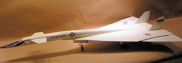
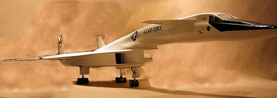
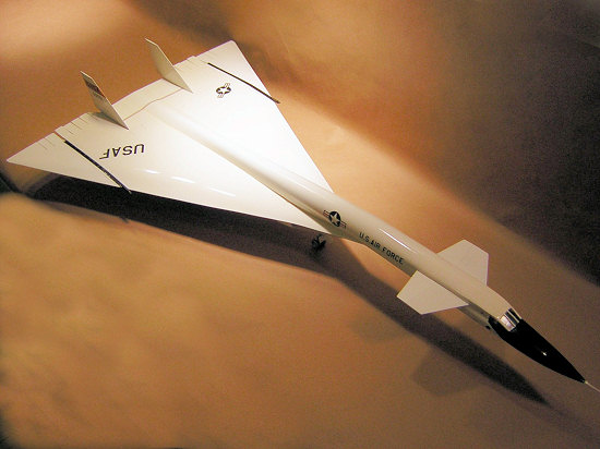
The envisaged order for hundreds of B-70’s was whittled down to just 3 research planes, then further cut to 2. This ERTL kit supposedly represents the #1 ship, though it would take an educated eye to spot the external differences, mostly a 5 degree dihedral added to the second airframe.
 Mechanical glitches
turned many test flights into near death experiences. The hydraulic system
sprung repeated leaks, but at 4000 pounds pressure per square inch what system
wouldn’t. Unforeseen flying characteristics demanded counter intuitive pilot
responses. Even taxiing was a memorable event, with the flight deck bounding up
and down, half a hundred-foot-fuselage-length ahead of the nose gear. Most of
the technical problems were corrected in the second prototype; but the
computerized controls that could tame the flight characteristics were still a
decade or two in the future.
Mechanical glitches
turned many test flights into near death experiences. The hydraulic system
sprung repeated leaks, but at 4000 pounds pressure per square inch what system
wouldn’t. Unforeseen flying characteristics demanded counter intuitive pilot
responses. Even taxiing was a memorable event, with the flight deck bounding up
and down, half a hundred-foot-fuselage-length ahead of the nose gear. Most of
the technical problems were corrected in the second prototype; but the
computerized controls that could tame the flight characteristics were still a
decade or two in the future.
The “near” was dropped from “near death” on 8 June 1966. An F-104 chase plane got caught in the complex vortex swirling off the second B-70’s drooped wing, was flipped across the Valkyrie’s back, ripped off both of the X-plane’s fins and part of its port wing before evaporating in it’s own fireball. Pilot Al white managed to eject as the plane fell into a flat spin. Co-pilot Maj. Carl Cross died in the crash. Test pilot Joe Walker was killed in the chase Starfighter.
After the destruction of the #2 plane (“loss”, the usual term is so insufficient, suggesting that like a set of car keys it was merely misplaced) the program continued for a while with the modified, speed restricted “AV/1” airplane, but the Air Force soon bowed out. NASA flew 33 more missions, then on 4 Feb ’69 delivered it to the Air Force Museum in Dayton OH, where it resides today, reportedly still soaking up an unfair share of maintenance funds commensurate with its size, but, some would argue, not with its historical significance.
My, for someone who promised just a snippet of a summary I sure have rambled on. But a big kit deserves a big history.
| THE KIT |
AMT / ERTL (what does that stand for, anyway?) passed this off as a “limited edition” of “only” 15,000, which seems to me awfully unlimited. The huge reinforced box contains, in addition to several gray sprues and bagged parts, a poster of the airplane and its pilots, a set of 3-view drawings which differ from photographs and give little construction assistance, a “Certificate of Authenticity”, which certificates and authenticates Lord only knows what, and a brass coated name plate. The first 3 items served passably well as desk blotters for all the wet sanding that needed to be done. The last item was simply chucked. Instructions were comprised of clear diagrams and text, though construction is simpler if a different sequence is followed.
A kit this size could have been parsed into many more parts, which would actually have simplified construction; but perhaps they were shooting for a “quick build” audience. Surface detail is sparse, as it must have been on the real thing, and is represented by both raised and incised lines, the latter around the engine bays a bit wide and deep.
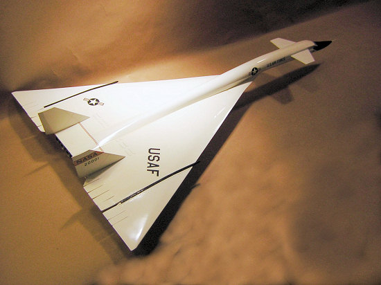
 Parts are provided to
build the plane in two configurations. Separate wing hinge sets allow for wing
tips up or drooped to 25 degrees. I understand wings were never drooped on the
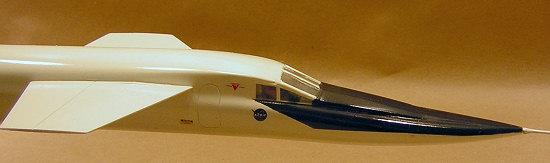
ground, as they would scrape. There are 2 windscreens: a subsonic “stepped”
transparency and one with the fairing ramp raised, which, histories indicate,
would block a view of the horizon and reflect the ground, inducing vertigo.
Parts are provided to
build the plane in two configurations. Separate wing hinge sets allow for wing
tips up or drooped to 25 degrees. I understand wings were never drooped on the
ground, as they would scrape. There are 2 windscreens: a subsonic “stepped”
transparency and one with the fairing ramp raised, which, histories indicate,
would block a view of the horizon and reflect the ground, inducing vertigo.
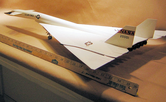
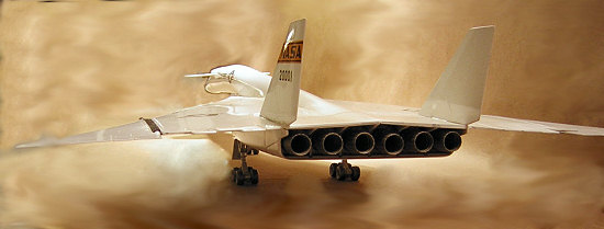
The main item on the sprues are wheels, or rather wheel halves – more than I have ever seen in a kit – 20 in all, as there were 4 on each main gear truck and two on the nose gear, which as mentioned, was actually affixed a considerable distance aft of the nose. (4 X 2 = 8 + 2 = 10 X 2 = 20! Yes, I got that right!). The wheel halves are flattened, but not realistically. They look more abraded than weighted, as if the pilot had landed with locked brakes. Been there & done that. You would not believe what an airplane tire costs!
A larger consideration makes this a thanks-but-no-thanks proposition. In the absence of shelf space as wide as the 1:1 USS Enterprise, the model will have to be hung from the ceiling. The simulated final landing approach with flattened tires looks singularly inappropriate. Adding filler and re-contouring all 10 was too much trouble (many subroutines on this project were too much trouble) so I simply smoothed out the sharp edges until the “off-rounding” was to my presbyopic eyes unnoticeable.
The parts
break-down, or rather un-break-down, causes one major migraine. On the center
wing section and droop tips the elevon “fingers” are integral with the upper
surface. They wrap around the trailing edge to the underside, but the joint
with the lower wing half is not, as might be expected, along the hinge line, but
across the center of the control surface tabs. This results in
 a seam and step that is
virtually impossible to satisfactorily fair. Molding the tabs as separate parts,
or at least as banks, would have improved the look and ease of assembly. If
anyone out there in Webland was involved in the engineering, or is otherwise in
the know, it would be interesting to hear the rationale behind the way they
were done.
a seam and step that is
virtually impossible to satisfactorily fair. Molding the tabs as separate parts,
or at least as banks, would have improved the look and ease of assembly. If
anyone out there in Webland was involved in the engineering, or is otherwise in
the know, it would be interesting to hear the rationale behind the way they
were done.
Anyone wanting to do the model up right might think about cutting away all the molded-in fingers and replacing them with tapered-down thick card stock. I had to do this with one that I broke and could not smoothly repair. It was fairly easy, but I started with a pre-tapered tail fin from a wiped-out jet of some sort.
On the same subject, the spaces between the elevon fingers is only partly cut through, which looks very toy-like. I completed the separation with a razor saw; but that was a big mistake as it weakened the tabs and allowed them to flex, repeatedly cracking away the filler that had to be applied to said seam. That’s also how I broke one off.
| CONSTRUCTION |
I deferred assembly of the flight deck and landing gear so I could jump right into joining that immense swath of wing. When halves come together a large gap results where the wrap-around leading edge molded with the top joins the bottom. This closes up if the assembly is curved downward with tape while it dries. If that isn’t the way things are supposed to be, then a slight anomalous anhedral is induced, which only an aerodynamicist would spot anyway.
If I had the whole thing to do over again, which I wouldn’t even if I could, but I couldn’t ‘cause the limited edition is long sold out, I would amend the build sequence and cut away the webbing between the wing halves to gain access to the rear fuselage section. That would cure a problem caused by the latter assembly being slightly too narrow. Through this access port a section of sprue rod could be inserted to fatten it into shape in-situ. This job had to be done through tedious trial and error dry fitting.
 I might also replace the parts
forming the underside of the wing apex with a single piece of card stock. All
the seams down there make a real mess of what is supposed to be a smooth
surface. Purists might find that the tip of that apex, what was called the
horizontal splitter plate, is too round. Photos show it as an acute dagger point
where it joins the vertical fuselage pylon. Filing it would booger up the
leading edge contour and there’s just no easy way for a fix. That splitter
caused problems on the real plane when it disintegrated and flew into the engine
inlets destroying three of the jets.
I might also replace the parts
forming the underside of the wing apex with a single piece of card stock. All
the seams down there make a real mess of what is supposed to be a smooth
surface. Purists might find that the tip of that apex, what was called the
horizontal splitter plate, is too round. Photos show it as an acute dagger point
where it joins the vertical fuselage pylon. Filing it would booger up the
leading edge contour and there’s just no easy way for a fix. That splitter
caused problems on the real plane when it disintegrated and flew into the engine
inlets destroying three of the jets.
One change I did make was in the fuselage building sequence. The instructions call for mating the clamshell halves of the forward and aft sections before joining them into one long tube. It was easier to make two short tubes and stick them end to end then to the wing. I had planned to leave off the forward tube and paint it separately, but the seam would be an eyesore. It was still an eyesore when they were joined pre-painting. The filler was impossible to smooth with the molded-in vent projections, so I did the obvious – sand them off to represent them closed. That also meant removing the glued-in forward vent, filling the wound with card stock, then puttying over. A smooth snake-shape also meant sacrificing the molded-in VHF antennae. Pics of the plane are inconclusive of whether the vents were always open on the ground. If they were it’s another “who cares?” issue. Nor do they clearly show the antennae. The engraved escape hatch outlines were also a sanding casualty. Re-scribing them was another job that was too much trouble and time consumed for too little gain.
 The transverse seam where the
fuselage tube met the wing aft center section kicked up more fuss than the
forward joint. Lots of filling. Lots of filing. Lots of putty. Lots of sanding.
Lots of primer. Lots of more sanding. The raised panel lines on the back end
also disappeared in the process.
The transverse seam where the
fuselage tube met the wing aft center section kicked up more fuss than the
forward joint. Lots of filling. Lots of filing. Lots of putty. Lots of sanding.
Lots of primer. Lots of more sanding. The raised panel lines on the back end
also disappeared in the process.
Those contouring tasks were a cinch compared with the repair job on the control surface fingers. The entire project was about to experience CFIT (Controlled Flight Into Terrain) when I remembered my long-stroke inline sander that I had created from an unused electric carving knife. (All electric carving knives are unused.) That tool also doubles as a paint shaker. The conversion article is archived somewhere on this site, but as a quick recoup: Chop all but about 3” from the blades and dull the edge on a grinding wheel. For the sander, re-insert one blade, and using foam mounting tape or double-sided carpet tape stick on to it a rectangle of appropriate grit W/D abrasive. Lay on plenty of soapy water and wail away. The electric in-line sanding action took less than 5 minutes to acceptably fair the putty on the elevon tabs.
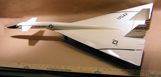
| COLORS & MARKINGS |
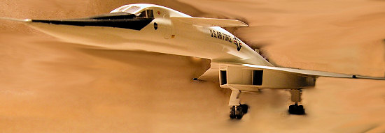
The Valkyrie’s basic white scheme underwent minor modifications during the planes 10 or so flying years. In early flights the engine inlet area and engine bay were left natural metal. Wing hinges oscillated between black and white. I settled on all white with black hinges and the NASA logos on the fins. Photos indicate the engine exhaust area and burner cans were semi-glossy-ish black. The painting guide called for gray. Model Master Engine Exhaust seemed the logical compromise.
After smoothing out all seams with 400 grit and polishing the whole she-bang with Soft Scrub cleanser I figured the airframe was ready for paint. A first coat of flat white primer showed up all manner of scratches; so back we went to the sanding shop and stepped down all the way to 1500 grit.
The next
problem was putting down enough paint to start hiding all the putty and stuff.
My trusty Badger single action with a medium tip was not up to the task of
covering that much area, even with both pressure and paint flow set to full
throttle. I toyed with using a spray can, found an old half-used one and tried
it on some wrecked wing parts. Just seemed to make a mess. That’s
 when I recalled the El Cheapo
Chinese knock-off external mix airbrush I had gotten from Harbor Freight for
only $5. It had been relegated to the garage for fixing car dings. A bit of
experimentation provided the formula for schpritzing out a wide swath without
runs sags and puddles. Testors, from the little square bottles (the only
enamel I could find even at Hobbytown), was cut 1:1 with household paint
thinner. MM Airbrush thinner, my usual choice, seemed to dry too fast to allow
leveling on all that square footage. I cranked the pressure up to max, the
regulator read 60lbs., opened the nozzle to the threshold of a wide fan, and
sprayed with a steady slow pass at only 2 – 3 inches.
when I recalled the El Cheapo
Chinese knock-off external mix airbrush I had gotten from Harbor Freight for
only $5. It had been relegated to the garage for fixing car dings. A bit of
experimentation provided the formula for schpritzing out a wide swath without
runs sags and puddles. Testors, from the little square bottles (the only
enamel I could find even at Hobbytown), was cut 1:1 with household paint
thinner. MM Airbrush thinner, my usual choice, seemed to dry too fast to allow
leveling on all that square footage. I cranked the pressure up to max, the
regulator read 60lbs., opened the nozzle to the threshold of a wide fan, and
sprayed with a steady slow pass at only 2 – 3 inches.
Despite clean-room precautions, that pressure picked up multiple dust “picks”; and/or spat out a few splatters. Between-coat rubdowns of wet 1500 grit produced an acceptable, but not glass perfect gloss after 3 or so sprayings. As the paint cured and the project moved toward decaling, the filler patch that had replaced the forward fuselage vent sprung its trap; contorting into a ghastly convoluted sink hole. The seam between the forward and rear fuselage tubes joined in on the fun, taking advantage of thermal expansion to crack its meticulously sanded filler. Of course those verdamte elevon fingers also added their share of mischief.
The Secret Model Airplane Building Room is by necessity and design a narrow galley, efficiently laid out for assembling standard sized one seventy seconders, but ill proportioned for maneuvering therein a hose-nosed elongation like the XB-70. Inevitable (but avoidable) encounters with walls and protruberances broke and bent those troublesome digits, re-exposing their poorly positioned seams that had demanded so much attention. One step forward, three back. Four quick-succession doses of Dewars were required to forestall a styrene-stomping snit.
Once the
ETOH took effect I was calm enough to devise an unlikely unguent. I had several
squeeze bottles of heavy bodied acrylic paint, about the consistency of Elmer’s
Glue and bought for some long forgotten purpose for only 44¢ apiece in
Wal-Mart’s artsy-craftsy department. Experimentation showed that they made
effective post-paint fillers. After dribbling and dabbing with a
 brush into the depressions, they
hardened with little shrinkage within a few hours to a sandable patch that
easily feathered with ultra fine grit into the surrounding paint. The boo-boos
had to be re-airbrushed, but a buffing with Colgate “Whitening” Toothpaste,
containing baking soda, erased the overspray and equalized the gloss into an
invisible fix. I had tried toothpastes before, but found them lacking in
abrasive uncus. Will have to play with this stuff for polishing canopies, and
perhaps give it a try on teeth.
brush into the depressions, they
hardened with little shrinkage within a few hours to a sandable patch that
easily feathered with ultra fine grit into the surrounding paint. The boo-boos
had to be re-airbrushed, but a buffing with Colgate “Whitening” Toothpaste,
containing baking soda, erased the overspray and equalized the gloss into an
invisible fix. I had tried toothpastes before, but found them lacking in
abrasive uncus. Will have to play with this stuff for polishing canopies, and
perhaps give it a try on teeth.
The kit decals appeared on the sheet to be extremely thick with prominent carrier films. They were, making by comparison 1960’s Airfix markings look like the latest off the Alps printers at Superscale or Propagteam. They acted less like waterslide transfers than peel and stick labels, which is exactly how they had to be applied. They did adhere well, but any excess fluid had to be mopped up instantly or droplet markings would form that were impervious to all washing and even polishing. I managed to locate replacements for some of the insignia, but they mismatched the too-dark kit markings. After a heavy coating of Future the paint job looked acceptable, but standards were steadily declining as the project neared completion; a goal that seemed never to inch nearer.
| FINAL CONSTRUCTION |
The windscreen fit passably well, but a gap with the fuselage roof had to be puttied (with Wal-Mart paint), sanded, and touch-up airbrushed. During that process the elevon fingers continued their game of flex, crack, and break, while the fore-aft fuselage joint expanded again and fractured the thrice-repaired filler and paint. I had the airframe supported on a cradle, with its neck stretched out looking invitingly like a thanksgiving turkey awaiting its fate. It took great self control (and a few more draughts of Dewars) to keep from slipping next door into the garage, retrieving a crash axe from behind the pick-up seat, and ending with one swift chop the bird’s misery and my own.
Wheels. Ten wheels. Twenty halves, that had to be cut from their sprues, de-flashed, glued together, sanded, painted, masked, painted again, and finally affixed in place. Tedious. Boring. Time consuming. From now on all my models will be done with wheels retracted – even the fixed gear planes.
 The heat generated by Mach 2+
flight required tires that were impregnated (or maybe just coated) with
aluminum. Painting instructions called for gear legs, hubs, and tires to be
sprayed silver, but photos show that black poked through slightly on the
sidewalls, and in a much darker circumference band where the rubber met the
runway (actually the dry lake bed). The SR-71 parked at NASM’s IAD annex (just a
hop, skip, jump and $12 parking fee from my home) has the same type of wheels,
but they are not really silver, just a worn and dirty gray. I first masked the
hubs with DIY punch-out discs of tape (Watch FSM Magazine for an upcoming
detailed article), sprayed the tires Testors “rubber”, removed the masks and
sprayed everything again with non-buffing metalizer, just misting from the sides
and avoiding the tread area.
The heat generated by Mach 2+
flight required tires that were impregnated (or maybe just coated) with
aluminum. Painting instructions called for gear legs, hubs, and tires to be
sprayed silver, but photos show that black poked through slightly on the
sidewalls, and in a much darker circumference band where the rubber met the
runway (actually the dry lake bed). The SR-71 parked at NASM’s IAD annex (just a
hop, skip, jump and $12 parking fee from my home) has the same type of wheels,
but they are not really silver, just a worn and dirty gray. I first masked the
hubs with DIY punch-out discs of tape (Watch FSM Magazine for an upcoming
detailed article), sprayed the tires Testors “rubber”, removed the masks and
sprayed everything again with non-buffing metalizer, just misting from the sides
and avoiding the tread area.
Painting the inside of the gear doors and wheel wells posed a color-pick problem. The instructions said green, which seemed wrong because nothing else on the airplane was; and chromate sort of disappeared with the arrival of jets. Silver or white were more logical, and I went with the latter out of laziness.
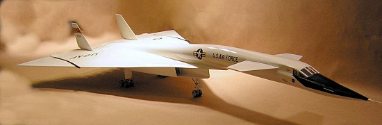
Once the legs were in place, the fins, canards, and wing tips went on to complete the airframe and let it down off its perch. The latter two surfaces are noticeably whiter than the rest of the plane because, lacking decals, they escaped the heavy coating of Future that bestowed a yellow tinge. The bowsprit was the last part in place because affixing it any earlier would have given it the opportunity to vie with the elevon fingers for the title of most broke appendage.
| CONCLUSIONS |
Certainly no museum piece. Gobs of goobers & “good ‘nuf’s”; but statistically adjusted for area, the Boogers Per Square Foot Quotient would, to mash two sports metaphors, be on par with my normal batting average. Not a bad or particularly difficult kit (if you can still find one); but certainly a poor choice to revive a flagging interest in model airplanes.
April 2007
Copyright ModelingMadness.com
If you would like your product reviewed fairly and fairly quickly, please contact the editor or see other details in the Note to Contributors.
Back to the Review Index Page 2019