Red Bear 1/48 King Air B200
| KIT #: | |
| PRICE: | $110.00 |
| DECALS: | Two options |
| REVIEWER: | Pat Earing |
| NOTES: | Resin kit |
| HISTORY |
The Beech King Air is the world's most popular turboprop aircraft.
Beech Aircraft
Corporation developed the King Air in 1964 as a compromise between piston-engine
and jet aircraft and the design quickly found success. The King Air can fly
farther and higher than piston-engine aircraft, and, unlike many jets, it can
land on the short runways of most small airports. With the three different
models, including the C90B, still in production as of 2001, this aircraft
remains the primary business aircraft for small to mid-size companies, and it is
an integral part of the flight inventories of many larger corporations.
Since its incorporation in 1932, Beech Aircraft was a successful builder of
civil and military aircraft. After Walter Beech's death in 1950, his wife and
co-founder, Olive Ann, became president and chairman of Beech and she continued
the profitable aircraft production lines, while also diversifying into other
aerospace endeavours. In 1959, Beech Aircraft introduced the Model 65 Queen Air
to fill the gap between the six-seat twin-Bonanza, a derivative of the
single-engine Bonanza introduced in 1947, and
 the Super 18, a deluxe version of
the classic Beech 18. The Queen Air featured the low-wing, all-metal, tricycle
design typical of Beech's post-war aircraft, carried seven to nine passengers,
and featured two horizontally-opposed 340-hp Lycoming engines. Subsequent
improvements included a swept tail and a pressurized fuselage, but when
turboprop engines were added to a Queen Air 88 in 1964, it was re-designated the
King Air 90.
the Super 18, a deluxe version of
the classic Beech 18. The Queen Air featured the low-wing, all-metal, tricycle
design typical of Beech's post-war aircraft, carried seven to nine passengers,
and featured two horizontally-opposed 340-hp Lycoming engines. Subsequent
improvements included a swept tail and a pressurized fuselage, but when
turboprop engines were added to a Queen Air 88 in 1964, it was re-designated the
King Air 90.
In August 1963, Beech Aircraft announced the King Air design to meet the
requirements of executive and corporate business travel for six to nine
passengers, using turboprop engines to bridge the gap between piston-power and
jet aircraft. The first King Air, powered by Pratt & Whitney Canada PT6A-6
engines, flew on January 20, 1964 and, after the prototype completed a 230-hour
test program, the design received its type certificate on May 27, 1964. The
first production aircraft deliveries began in late 1964.
The design was a low-wing cantilever monoplane of aluminum construction with
retractable tricycle landing gear. To improve its utility and safety in changing
flight conditions, standard equipment, that had been optional on the Queen Air,
included de-icing boots on the leading edges of the wings, fin, and tailplane.
Flight instruments allowed for all-weather capabilities and various
communications and navigation packages included autopilot, radio, and radar
systems. The Model 90 had two seats in the cockpit and four reclining passenger
seats facing each other in the cabin, with options for a two or three-place
couch for passengers. Air conditioning and soundproofing also improved passenger
comfort in the cabin. Two 500-hp P&W Canada PT6A-6 turboprop engines with
three-blade Hartzell propellers gave the King Air a top ceiling of 27,400 feet
and a range of 1,565 miles at 270 mph. Piston-powered aircraft could not match
this performance while emerging jet aircraft of the 1960s used turbojet engines
that were high-priced, noisy, and had high fuel consumption.
Rather than investing in a completely new and expensive technology, Beech built
a vastly improved and marketable business aircraft from its existing production
line. After the King Air's initial success, Beech concentrated on continuous
upgrades to appeal to a range of executive and corporate needs that resulted in
the creation of the Models 90, 100, 200, 300, and 350.
The King Air 200 is a continuation of the King Air line, with new features
including the distinctive T-tail, more powerful engines, greater wing area and
span, increased cabin pressurization, greater fuel capacity and higher operating
weights compared to the King Air 100.
Beech began design work on the Super King Air 200 in October 1970, resulting in
the type’s first flight on October 27 1972. Certificated in mid-December 1973,
the King Air 200 went on to be the most successful aircraft in its class,
eclipsing such rivals as the Cessna Conquest and Piper Cheyenne. Today the King
Air 200 is the only one of the three in production.
The improved B200 entered production in May 1980, this version features more
efficient PT6A42 engines, increased zero fuel max weight and increased cabin
pressurization. Sub variants include the B200C with a 1.32m x 1.32m (4ft 4in x
4ft 4in) cargo door, the B200T with removable tip tanks, and the B200CT with tip
tanks and cargo door. The Special Edition B200SE was certificated in October
1995 and features an EFIS avionics suite as standard.
 Various special mission King Air 200s and B200s have been built, including for
navaid calibration, maritime patrol and resource exploration. In addition
several hundred Super King Airs have been built for the US military under the
designation C12. C12s perform a range of missions from electronic surveillance
to VIP transport. The 1500th commercial King Air 200 was built in 1995. In 1996
Raytheon dropped the `Super’ prefix for all 200, 300 and 350 model King Airs.
Various special mission King Air 200s and B200s have been built, including for
navaid calibration, maritime patrol and resource exploration. In addition
several hundred Super King Airs have been built for the US military under the
designation C12. C12s perform a range of missions from electronic surveillance
to VIP transport. The 1500th commercial King Air 200 was built in 1995. In 1996
Raytheon dropped the `Super’ prefix for all 200, 300 and 350 model King Airs.
As part of Ireland's obligations to the European Union, the IAC patrols 132,000
square
miles (342,000 km²) of sea. The Air Corps previously employed three Beechcraft
200
Super King Air for this duty. However, two of the Super King Airs were disposed
of in the
1990s, and the third was allocated to transport duties.
Two CASA C235-100
maritime
patrol aircraft now undertake these patrols - and were upgraded in 2006/2007 by
EADS CASA to the FITS Persuader standard with enhanced radar, forward looking
infra-red equipment and a new electronic and avionics suite.
Nearly 50 years since its introduction, the King Air series is still the king of the turboprops and fills a significant niche in the business aviation marketplace.
| THE KIT |
Hot on the heels of Red Stars’ RC-12K release in 1/48 scale
comes Red Bear Resin with a 1/48 scale King Air B-200.
As far as I know this resin kit is the first release for the Russian
company Red Bear.
Red Bear’s boxing of the B-200 represents the second 1/48 scale King
Air released, but in a more traditional airframe layout, or shall I say, with
civilian/military version buildable. Red Bear’s kit comes in two boxing’s; the
first with decals for Royal Air Force King Air, and the second with decals for
the recent Centennial of Naval Aviation (CONA) Navy C-12’s.
 My kit was purchased through DMC Models and arrived at my
door in a rather crushed outer box in about two weeks.
In comparison with my previous RC-12K purchase from Red Star, the
parts for the B-200 were simply packaged
and shipped loose inside the kit box without any additional packaging
materials.
As a result, most of the small resin parts had been damaged in some manner or
form.
My kit was purchased through DMC Models and arrived at my
door in a rather crushed outer box in about two weeks.
In comparison with my previous RC-12K purchase from Red Star, the
parts for the B-200 were simply packaged
and shipped loose inside the kit box without any additional packaging
materials.
As a result, most of the small resin parts had been damaged in some manner or
form.
My first impression is that this kit is, if not the same
as Red Stars’ casting(s), it is very similar; especially with the parts layout
and construction.
Honestly, the kit looks nearly identical, and represents a fine first
offering for an overlooked aircraft.
Overall, the panel lines are very petit, and look great.
The biggest single disappointment for me is that the very large and
prominent passenger cabin windows of the King Air series are not cast as
openings and the kit does not include any of the aft passenger cabin interior.
Rather, Red Bear has simply scribed the windows and left it to the
modeler to paint them on the sides of the aircraft.
This is unfortunate, as drilling the windows will be a difficult
undertaking due to the shape of the fuselage and the fact that some of the
windows are oval rather than round.
Even if Red Bear had chosen not to include the cabin interior, I would
have much preferred to have the windows open-especially in this scale.
For the cockpit windows Red Bear has included an entire
forward upper fuselage section in clear vacuformed plastic.
This part represents a major construction hurdle as it will require
the modeler to carefully remove the entire top of the forward section of the
aircraft cabin from both fuselage halves.
Although images of
the cutout are provided in the instructions, no measurements or alignment
references are given and there are no obvious panel lines to use. Two canopies
are provided and although not crystal clear, they appear adequate and should
clear up nicely with a coat of Future.
This looks to be the crux of the build, as it will be a seriously
challenging achievement to cut and install the canopy parts.
An adequate flight deck is included with seats and floor
and instrument panel.
A minimum of detail is also provided for the side panels; although the
detail provided does not appear to be accurate based on images of B200 cockpits
I have seen.
In regard to the fuselage castings, Red Bear’s offering
has a clean mating surface for gluing; however, they do not include any
alignment pins and the parts also suffer from a considerable amount of warpage.
An even larger issue is that the fuselage halves did not match for
length with the left half being almost ¼ of an inch short at the tail (A scale
foot in length!)
Clearly this kit will not fall together, and in fact will require some
modeling skills to achieve a good result.
Finally, Red Bear has not included the large ventral strake that the
King Air wears, leaving it up to the modeler to create this from card stock;
with no measurements or a placement guide.
 The wings look okay, but will need a bit of clean up
especially at the trailing edges which had been seriously damaged in my example
during shipping.
The forward engine section is a separate casting.
I was curious to see if the engines matched the rest of the wing
bulkhead in size for both diameter axis and they did, lining up perfectly.
Unfortunately, the wings also suffered from warpage that seriously
impacted the attachment of the engines, as we will discuss later.
Finally, the ailerons have been cast separate; a nice touch that is
seldom provided by resin kit manufacturers.
The wings look okay, but will need a bit of clean up
especially at the trailing edges which had been seriously damaged in my example
during shipping.
The forward engine section is a separate casting.
I was curious to see if the engines matched the rest of the wing
bulkhead in size for both diameter axis and they did, lining up perfectly.
Unfortunately, the wings also suffered from warpage that seriously
impacted the attachment of the engines, as we will discuss later.
Finally, the ailerons have been cast separate; a nice touch that is
seldom provided by resin kit manufacturers.
A major construction hurdle is the vacuformed canopy
section provided by Red Bear for the forward cockpit windows.
This insert will require the modeler to carefully remove the entire
top of the forward section of the aircraft cabin.
Although images of the cutout are provided, no measurements or
alignment references are given. Two canopies are provided and although not
crystal clear, they appear adequate and should clear up nicely with a coat of
Future. This
looks to be the crux of the build, as it will be a seriously challenging
achievement to cut and install the canopy parts.
All of the small parts come bagged in three re-sealable
baggies. One
aspect of the King Air is its prominent nose gear and Red Bear has nailed this
casting. I
have spent many years tugging King Airs around tarmacs, and from
experience/memory I can say that these gems look the part.
How they hold up over time to the inevitable weight of the kit is
another issue.
The Main gears are amazingly well cast and incorporate a unique system for
creating the largest mounting surface possible given the rather small wheel
size. Red
Bear have cast the inner hub/brake details onto the main legs allowing for not
only alignment, but a large, strong attachment surface for the main wheels.
All three wheel bays are provided for with separate side panels
providing a very detailed area for the nose bay and adequate if sparse detail
for the mains.
Red Bear includes a simple but adequate instruction sheet with parts list and images of parts placement. This is brief at best, but a significant improvement over what was included with the Red Star kit I purchased. No paint FS numbers are provided; however, an adequate decal placement guide is included. The decals themselves look to be in register and provide markings for two different Royal Air Force King Airs.
| CONSTRUCTION |
As with all of my resin kits I begin construction by
giving all of the parts a warm soapy wash to remove any leftover release agent.
This is important as I have proof that both glue and paint have a hard
time adhering to whatever chemicals manufactures use to allow the resin to come
out of the molds.
At this time I also used very hot water to soak and slightly bend the
fuselage halves back to a semblance of straight as there was a considerable
amount of warpage present with my kit.
 Once things had dried, I began construction-In this case
marking and drilling the round and oval fuselage windows and painting the entire
inside section of each fuselage half with Model Master Light Gull Grey enamel
(FS 36440.)
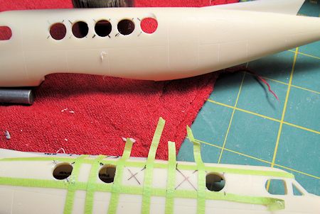
In order to get things perfectly aligned to the scribed windows on the fuselage
sides, I used 1/8th inch masking tape, stretched along the top and
bottom edge of each window opening as scribed, for the entire length of the
fuselage. I
then used smaller sections of tape set 90 degrees (using a small framing square)
to the top and bottom tape line to find the side edges.
Again these lines were set to the scribed ‘opening’ for each window
and required some patience to obtain both square in the corners and true to the
scribed window openings.
Once all these lines were set I used a sharpie and a straight edge to
draw diagonals for each window hole so as to find the exact center of each round
opening. At
this point I made a solid foam/styrene insert for each fuselage half to provide
support during the drilling process.
For these I used inch and a half thick pink insulating styrene and a
sharp #11 blade and carved inserts until they fit reasonably well.
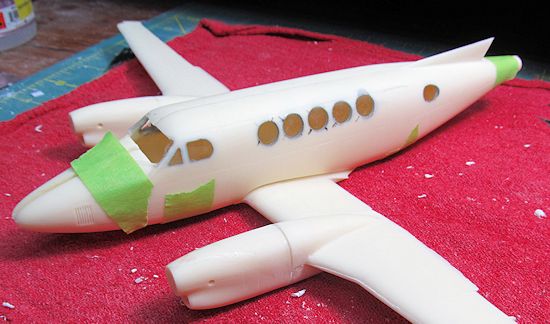
The next step was to actually drill out the window openings.
Using a ½ inch drill bit chucked into my wood shop drill press I
carefully drilled at the slowest rpm setting into the resin, using a soft
pressure on the lowering lever.
The crux of this operation is that the fuselage is rounded in both
fore/aft and circumference planes-a drill press is a must to get accurate
placement and no movement of the drill bit during the drilling process.
Although nerve wracking, this method worked well and I only
experienced chipping/tear out on the very last window that was easily repaired
with automotive bondo filler.
The rear most tear-drop shaped windows required two drill sizes, but
the process was the same for finding the center of each hole that needed to be
drilled. Finally,
these openings required careful trimming with an Exacto knife to remove excess
material between the two holes and achieve the correct shape for the opening.
Once things had dried, I began construction-In this case
marking and drilling the round and oval fuselage windows and painting the entire
inside section of each fuselage half with Model Master Light Gull Grey enamel
(FS 36440.)
In order to get things perfectly aligned to the scribed windows on the fuselage
sides, I used 1/8th inch masking tape, stretched along the top and
bottom edge of each window opening as scribed, for the entire length of the
fuselage. I
then used smaller sections of tape set 90 degrees (using a small framing square)
to the top and bottom tape line to find the side edges.
Again these lines were set to the scribed ‘opening’ for each window
and required some patience to obtain both square in the corners and true to the
scribed window openings.
Once all these lines were set I used a sharpie and a straight edge to
draw diagonals for each window hole so as to find the exact center of each round
opening. At
this point I made a solid foam/styrene insert for each fuselage half to provide
support during the drilling process.
For these I used inch and a half thick pink insulating styrene and a
sharp #11 blade and carved inserts until they fit reasonably well.
The next step was to actually drill out the window openings.
Using a ½ inch drill bit chucked into my wood shop drill press I
carefully drilled at the slowest rpm setting into the resin, using a soft
pressure on the lowering lever.
The crux of this operation is that the fuselage is rounded in both
fore/aft and circumference planes-a drill press is a must to get accurate
placement and no movement of the drill bit during the drilling process.
Although nerve wracking, this method worked well and I only
experienced chipping/tear out on the very last window that was easily repaired
with automotive bondo filler.
The rear most tear-drop shaped windows required two drill sizes, but
the process was the same for finding the center of each hole that needed to be
drilled. Finally,
these openings required careful trimming with an Exacto knife to remove excess
material between the two holes and achieve the correct shape for the opening.
 The next step was to pour clear resin windows; however,
some decisions needed to be made in regards to the forward windscreens.
The kit comes with a beautifully vacuformed forward canopy section;
and it is expected of the modeler to cut the entire top of the cockpit off and
replace it with the clear vacuformed section.
Unfortunately, there are no clear panel lines to follow and no
dimensions or measurements included in the instructions for this procedure.
As such I decided to make all of the windows using resin and forego
the cutting.
The next step was to pour clear resin windows; however,
some decisions needed to be made in regards to the forward windscreens.
The kit comes with a beautifully vacuformed forward canopy section;
and it is expected of the modeler to cut the entire top of the cockpit off and
replace it with the clear vacuformed section.
Unfortunately, there are no clear panel lines to follow and no
dimensions or measurements included in the instructions for this procedure.
As such I decided to make all of the windows using resin and forego
the cutting.
Having
never used clear resin I consulted with a few people about what was the best
product to use and some tips for achieving good results.
In the end I ordered some Castin’ Craft Easy Cast resin from an online
vendor to the sum of $18.00 and read the instructions thoroughly.
The process seems tedious with the warning that not following every
step to the letter could result in a failed pour-oh my, STRESSFUL!
Using 3M clear packaging tape (This particular tape was recommended by
people working within the modeling industry, and worked very well-despite my
concerns that the texture of the adhesive would be transferred to the
windows-which did not happen, as promised.)
I carefully taped the outside of the fuselage so that each window
opening was conformal, and without wrinkles-easier said than done for sure.
Because the resin frames as provided by Red Bear are quiet petite, and
they are at a near ninety degrees to the fuselage sides I chose to do the
forward windscreens as a second pour.
Before setting the tape for the pour, I painted all of the window
opening edges, as these will be under resin, inaccessible and visible when
finished-Note to self, remember this step!
Once things were taped, I made a jig to hold each fuselage half solid
and level and set about mixing the resin.
Not such a problem except, the resin must be between 70 F and 85 F
when you start and throughout the curing process-my model area is in the
basement of our house and runs a consistent 55F-Huh, nothing for it but to take
this up stairs and start warm!
Once things were up to temperature, I began mixing the resin.
It is important that you have the ability to accurately measure the
two parts of the system, as well as have two clean containers and a stirring
utensil that is clean.
A note-use gloves! -I put on some latex gloves for this project, and
did not regret the decision.
Also, put down some newspaper or other cover if you are doing this on
the kitchen counter as I was.
The mixing is an entailed trial of mixing, waiting, mixing and
waiting-and if you did everything just right, when the resin cures in 24 plus
hours it will be clear and bubble free.
I clearly got it right, but it was stressful waiting to find out.
Once the resin was poured I placed the two fuselage halves near our
wood stove and covered them to keep out dust/lint etc. with a large cardboard
box. When I was
brave enough to look, things had cured clear and for the most part bubble free
and I set up and did the whole process again for the front windscreen sections.
Overall, this seems an adequate way to achieve large, multiple window
situations; but, maybe I just got lucky.
A final bit of resin pouring went into the wingtip
navigation lights.
Red Bear has cast a beautiful representation of the light fixtures and
such that the King Air carries.
Unfortunately, they do not include any way to cover this detail; as,
on the real 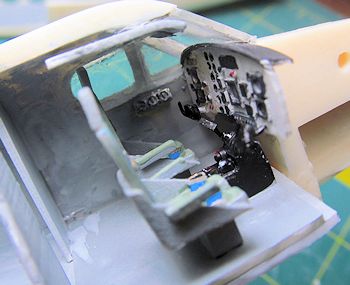 aircraft there is a clear plastic cover present.
To model this I first painted the appropriate details, then taped the
top, most visible section of the ‘cover’ with the 3M tape.
I made sure to tightly follow the contour of the wingtip and built a
small dam with tape around where the cover edges will be on the bottom.
I then went through the whole pouring process again.
This time, when the material was set I carefully shaped the bottom of
the cover with a sharp #11 blade and waited for the material to set hard.
After a couple of days I sanded the cover to final shape stepping down
from 320 grit sand paper to 1000 grit and a final polish with a fine
furniture/wood polish.
This system worked very well, covering the painted detail under a full
‘plastic cover’ like the real aircraft.
aircraft there is a clear plastic cover present.
To model this I first painted the appropriate details, then taped the
top, most visible section of the ‘cover’ with the 3M tape.
I made sure to tightly follow the contour of the wingtip and built a
small dam with tape around where the cover edges will be on the bottom.
I then went through the whole pouring process again.
This time, when the material was set I carefully shaped the bottom of
the cover with a sharp #11 blade and waited for the material to set hard.
After a couple of days I sanded the cover to final shape stepping down
from 320 grit sand paper to 1000 grit and a final polish with a fine
furniture/wood polish.
This system worked very well, covering the painted detail under a full
‘plastic cover’ like the real aircraft.
Now I began to paint and assemble the interior of the
flight deck.
The seats being adequate I simply added some masking tape seat belts painted
bright blue-a complete whim as I have no idea what color the belts used in the
IAC King Airs looked like, but I like the splash of color it provides.
I created an overhead console, detailed and painted as well as a large
center consol.
Both of my kits control wheels were destroyed so using fine copper wire I
made new ones and set them to the instrument panel with 1.5 MM plastic rod.
At this point I also created a new bulkhead between the flight deck
and cabin, floor for the cabin and aft cabin bulkhead.
Once a good fit for the floor/bulkheads was achieved I m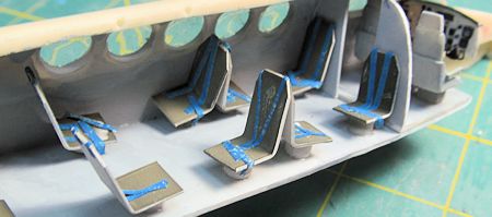 ade simple
plastic cabin seats painted and outfitted with masking tape belts.
These were mounted to short sections of ¼ inch plastic tubing and
inserted in a generous nine passenger cabin seating arrangement-again all
speculation as I was never able to come up with an image of what the IAC birds
looked like inside.
Before I glued the fuselage halves together I smashed several sections
of fishing weights flat to fit under the forward cabin floor sections-insurance
against a tail sitter.
I also tinted the cabin windows with Tamiya Smoke paint at this time
and glued the fuselage halves together with generous amounts of CA glue.
ade simple
plastic cabin seats painted and outfitted with masking tape belts.
These were mounted to short sections of ¼ inch plastic tubing and
inserted in a generous nine passenger cabin seating arrangement-again all
speculation as I was never able to come up with an image of what the IAC birds
looked like inside.
Before I glued the fuselage halves together I smashed several sections
of fishing weights flat to fit under the forward cabin floor sections-insurance
against a tail sitter.
I also tinted the cabin windows with Tamiya Smoke paint at this time
and glued the fuselage halves together with generous amounts of CA glue.
Assembly proceeded quickly at this juncture as I attached
the lower wing section and outer wing panel, engines and the vertical tail.
For the vertical tail and outer wing panels I dilled and inserted wire
to add strength at the joints.
The horizontal tail section was damaged in shipping but ultimately was
repairable; but the alignment of the part onto the vertical tail stub took me
two tries to get properly oriented to the plane of the wings.
This requires some thinking as, this rather fragile part was
thoroughly attached with CA glue, and it was not easy to get it back off again
in one piece.
None of these parts fit very well and despite careful fitting and fussing
there were sizable gaps and steps-oh well, break out the filler.
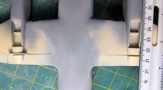
Although I had previously looked at the engines and
determined that they fit the profile of the wing nacelle correctly, I did not
look at them head on-UNTIL-I had solidly glued them on.
Unfortunately, the wing sections were both slightly warped, forcing
the engines to sit at different heights as seen from the front and, one of the
wing mounts was twisted so that the mounted was visibly turned to far from
vertical when viewed from the front.
Grrrrrrrrrr!
At least they were true in relation to the centerline of the fuselage.
Nothing for it but to cut them both off again, and regroup.
Not worrying about gaps, I made sure that all planes were true and
that I did not lose length in either engine overall length from spinner to wing.
In the end, they look okay, but did it ever take a ton of sanding,
filling and rescribing to get there.
 Before primer was applied I attached the ailerons and
flaps. These
did not fit well at all-and although I think it is cool to have the option to
animate the model, these types of options inevitably seem to create more work
than they are worth.
Such was the case here.
To fill the enormous gaps in the flaps at the nacelle hinge line I
inserted small sections of 30 thousands plastic.
The biggest problem with the ailerons was the fact that they were
seriously warped, and the hinge mounting points had been knocked off of the wing
sections. CA
glue and accelerator made these items conform, but I knocked them off at least
twice during construction…
To repair the trailing edge I used two inch masking tape attached to
the top of the wing and mixed up some actual bondo and filled the whole area.
Judicious sanding with 80 grit sand paper got things close and I
finished up with 180 grit sand paper.
Before primer was applied I attached the ailerons and
flaps. These
did not fit well at all-and although I think it is cool to have the option to
animate the model, these types of options inevitably seem to create more work
than they are worth.
Such was the case here.
To fill the enormous gaps in the flaps at the nacelle hinge line I
inserted small sections of 30 thousands plastic.
The biggest problem with the ailerons was the fact that they were
seriously warped, and the hinge mounting points had been knocked off of the wing
sections. CA
glue and accelerator made these items conform, but I knocked them off at least
twice during construction…
To repair the trailing edge I used two inch masking tape attached to
the top of the wing and mixed up some actual bondo and filled the whole area.
Judicious sanding with 80 grit sand paper got things close and I
finished up with 180 grit sand paper.
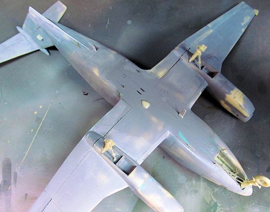
Once all the seams were cleaned up from the gluing process
I began the tedium of priming and sanding.
Ultimately this process took months as I put off working on the kit
and building others around it.
Through sheer perseverance, I realized that I was finally done with
the filling and sanding process, and it time to start rescribing.
After a rather uneventful evening spent rescribing the plane I made
the lower skeg/fin from 5 thousands scape plastic and started looking at the
antenna arrangement on the bottom of the fuselage.
For the ‘towers’ that hold the two wire antenna on the bottom I used
small brass tubing drilled and glued into the fuselage.
The other bumps and fins came from the kit except for the rearmost
antenna that I found in my parts bin.
 Finally, ready to paint I installed the landing gear legs.
The main gear legs required a small amount of cleanup, but overall are
well cast.
The legs set into a small slot at the back edge of the main gear wheel wells.
This placement allows for the proper ‘cant’ to the legs and an
appropriately large gluing area; unfortunately, the gear did not fit.
I enlarged the bay opening which is a small slot across the back of
the opening as well as thinning each mounting point on the gear legs. There are
no provisions for adjusting height on the main gear and the retraction arms do
not have a positive placement provided.
Finally, ready to paint I installed the landing gear legs.
The main gear legs required a small amount of cleanup, but overall are
well cast.
The legs set into a small slot at the back edge of the main gear wheel wells.
This placement allows for the proper ‘cant’ to the legs and an
appropriately large gluing area; unfortunately, the gear did not fit.
I enlarged the bay opening which is a small slot across the back of
the opening as well as thinning each mounting point on the gear legs. There are
no provisions for adjusting height on the main gear and the retraction arms do
not have a positive placement provided.
For
the Nose gear I started by gluing in the detailed side bay panels.
There is no obvious placement for these parts, so I placed them all
the way to the back of the bay.
This leaves an approximately ¼ inch ‘gap’ without detail at the front
of the bay, but after the gear leg and retraction arm are placed it is barely
noticeable.
The nose gear leg is a fantastic casting, and seems very fragile-I spent an
inordinate amount of time and care protecting this item once it was installed,
and it payed off in that I never broke the item once!
Placement in the bay is vague, and the gear leg is handed, so make
sure you have it oriented correctly before you commit to glue.
In an effort to increase the strength of the leg placement, I drilled
a hole the diameter of the top of the gear leg approximately 2MM into the front
center of the wheel bay.
The gear leg was installed with CA glue and accelerator.
The retraction arm placement is again, vague at best and did not meet
with any landmarks in the gear bay.
Make sure that the ‘arms’ of the apperature go forward of the actual
leg where they attach to it.
Finally, time to start thinking about paint…
| COLORS & MARKINGS |
 Best guesses, based on using images and placement on the
actual model led my masking session.
I used multiple types of masking tape from 3M and Tamiya to accomplish
the striping task.
For the tail pattern, I cut a 1.5 MM narrow section of Tamiya Kabuki
tape to stripe the narrowest line.
Once the wings, nacelles, nose, and tail were masked I covered the
rest of the exposed areas with paper and set to spraying.
For the orange I used MM International Orange (FS 12197 and Testors
number TS 2022) enamel reduced 50% with Testors universal thinner.
I sprayed three coats with dry to tack time between each.
Once dry, I removed all of the masking including the black areas and
sprayed the whole plane with Glosscoat.
Best guesses, based on using images and placement on the
actual model led my masking session.
I used multiple types of masking tape from 3M and Tamiya to accomplish
the striping task.
For the tail pattern, I cut a 1.5 MM narrow section of Tamiya Kabuki
tape to stripe the narrowest line.
Once the wings, nacelles, nose, and tail were masked I covered the
rest of the exposed areas with paper and set to spraying.
For the orange I used MM International Orange (FS 12197 and Testors
number TS 2022) enamel reduced 50% with Testors universal thinner.
I sprayed three coats with dry to tack time between each.
Once dry, I removed all of the masking including the black areas and
sprayed the whole plane with Glosscoat.
While the main model was drying I prepped and painted the
propellers.
The Kit propellers were slightly warped and proved to be a never ending source
of annoyance as I could not get them to stay true.
After clean up I sprayed the back sides of the blades Floquil Engine
Black and the front sides MM Light Gull Grey.
The deicer panel, manufacturer logo and tip stripes are decals
provided from my spares box.
The spinner was sanded with 600 grit sand paper and sprayed with MM
Blue Angels blue. Just at the point where I could handle the parts I applied
RubnBuff silver and polished it out with judicious use of SNJ buffing powder.
Decals were applied using a mix of left over roundels and
fin flash from a Max Decals sheet and the lettering from a custom sheet I
contracted from Bob at Sierra Scale Models.
The Beechcraft decal on the upper fillet came from the kit decal
sheet. No
surprises were encountered during decal placement, and when things had dried a
final coat of Glosscoat was applied and the window masking was removed.
The intake anti-ice panel was hand painted with MM chrome
enamel, and the exhaust stacks were first covered with MM Metalizer gunmetal and
then lightly over sprayed with Alclad Burnt Metal.
The interiors were brushed with engine black.
| FINAL CONSTRUCTION |
 Finishing things up took some time.
I carefully masked and sprayed the nose anti-glare panel matt with MM
Dullcoat and made some wipers from scrap etched brass material.
Antennas were reattached and wire strung with .07 diameter fishing
line. A
small collision beacon was created using thick CA glue on the bottom of the
fuselage and tinted with Tamiya red.
The strut sections of the landing gear legs were painted with MM
chrome enamel as well as the steering damper on the nose gear.
Finishing things up took some time.
I carefully masked and sprayed the nose anti-glare panel matt with MM
Dullcoat and made some wipers from scrap etched brass material.
Antennas were reattached and wire strung with .07 diameter fishing
line. A
small collision beacon was created using thick CA glue on the bottom of the
fuselage and tinted with Tamiya red.
The strut sections of the landing gear legs were painted with MM
chrome enamel as well as the steering damper on the nose gear.
Three small 2.0mm MV lenses were set into the kit landing
light ‘holders’ and attached to the nose gear leg.
At this time I attached the four exhaust stacks.
Weathering was kept to a minimum.
I gave the entire airframe a wash using black and burnt umber artists
oils reduced with Turpinoid.
This was the first time using oils, and I am not completely sold.
Honestly, I feel that the artists’ acrylics ‘stick’ better and are
easier to use and thin with just tap water-certainly cheaper.
I created exhaust staining on the wings using various shades of ground
pastels applied with a wide artists brush.
Finally, the wheels were painted with Floquil Engine Black and a spray
at the tread face with Weathered Black and attached with CA glue.
I managed to knock off both outer wheels at least once before the
picture session was completed, so even though it appears sound, the main wheels
are clearly a bit weak for glue area, and it might be worth drilling and pinning
with wire for a long term solution and strength.
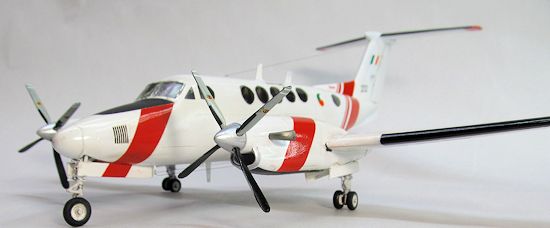
| CONCLUSIONS |
Well, it was a slog!
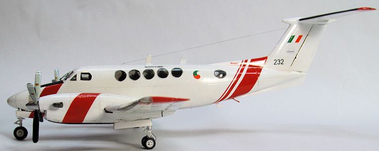
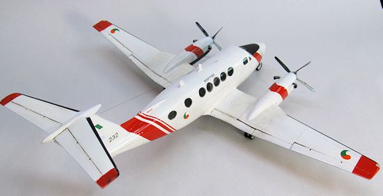
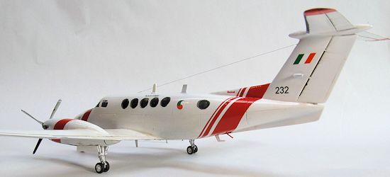
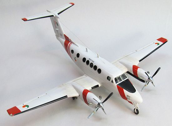
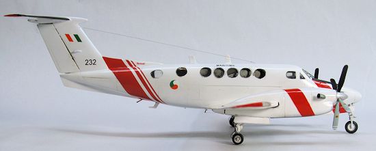
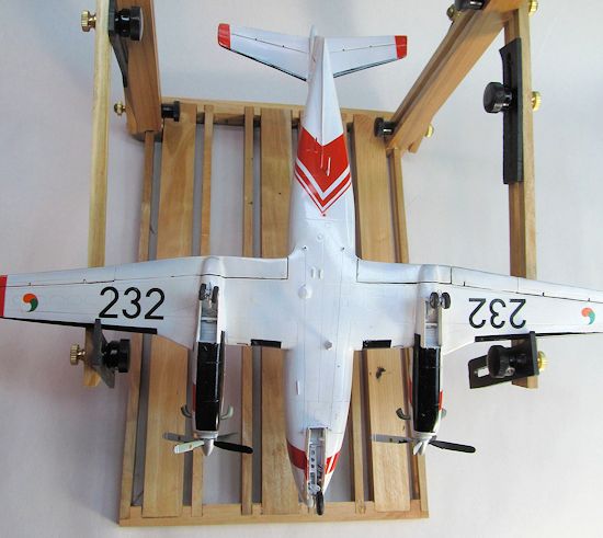
But in the end I persevered and now have a beautiful IAC King Air on
the shelf.
Although the panel lines and detail seem to be top notch, the kit is let down
with fit issues and warpage the likes of which I haven’t seen in a resin kit for
some time.
Emotionally I felt disappointed and I probably won’t be building the RC-12 kit
in my stash because of the magnitude of effort to achieve the end product-and
that says a lot.
Recommended to experienced resin kit builders, modelers with scratch
building experience and those who must have one no matter what.
| REFERENCES |
http://www.pilotfriend.com/aircraft%20performance/Beech/King%20Air.htm
Maxwell, Joe and Patrick Cummins.
The Irish Air Corps: An Illustrated Guide.
Max Decals Publications, Ltd., Ireland.
2009.
February 2013
If you would like your product reviewed fairly and fairly quickly, please contact the editor or see other details in the Note to Contributors.