Special Hobby 1/48 AJ-37 'Viggen'
| KIT #: | 48148 |
| PRICE: | $98.00 SRP |
| DECALS: | Three options |
| REVIEWER: | Andrew Garcia |
| NOTES: | Short run kit with photo etch parts |
| HISTORY |
The Saab 37 Viggen, meaning "Thunderbolt", is a Swedish single-seat, single-engine, short-medium range combat aircraft, manufactured between 1970 and 1990. It was the first canard design produced in quantity. Several distinctive variants were produced to perform the roles of strike fighter (AJ 37), aerial reconnaissance (SF 37), maritime patrol aircraft (SH 37) and a two-seat trainer. In the late 1970s the all-weather fighter-interceptor aircraft JA 37 was added. (Courtesy of Wikipedia) The type was retired from service in 2010.
| THE KIT |
The Special Hobby kit is the result of a collaboration with Tarangus models in Sweden. An initial plan to create a limited run kit with the Czech parent company of Special Hobby (MPM) and Tarangus evolved into an improved tool which captures the rugged lines of the Viggen and most of its unique features quite well. Tarangus released the kit in the JA 37 fighter-interceptor version, which is a later version of the airframe in early 2015. Special Hobby released its version of the same tooling several months later but representing the early AJ 37 Viggen known as the “Attack” version.
The kit plastic is almost identical between the two kits with the same plastic parts and similar assembly instructions. Parts for both versions are found on the plastic sprues so you do need to be careful and really read the instructions to get the correct version with its changed features. The Tarangus JA 37 has an extra sprue with JA 37 specific items such as the fuselage plug, cockpit tub, cockpit instrument display, VHF Antenna and ventral gun - all found on the same sprue that only comes with the Tarangus kit. In the Special Hobby box you will find 140 parts in grey plastic, ten parts in clear and markings for three subjects. The Special Hobby release includes a color etched fret with 31 pieces which are very well done and a big improvement over the Tarangus release. Tarangus did not include the color etched fret but relied on the modeler to supply any after-market for color etch details. They are available at additional cost from Maestro Models in Sweden. The Special Hobby kit etched metal includes parts such as those found on an Eduard zoom, the instrument panel, seat belts, rear view mirrors, etc. which contribute a great deal to the detailing of this kit and speeds up completing the cockpit area.
Although the details and most
of the parts are similar to mainstream manufacturers there are some areas
requiring putty, clamps and clean-up due to sometimes ill-fitting parts.
But, this concern is far less than earlier releases fr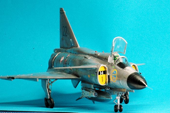 om limited run
manufacturers. I was pleased overall with the assembly of this kit and
really happy with some of the outstanding details. You do need to take your
time and apply some filler and test fitting of parts before committing them
to assembly with glue.
om limited run
manufacturers. I was pleased overall with the assembly of this kit and
really happy with some of the outstanding details. You do need to take your
time and apply some filler and test fitting of parts before committing them
to assembly with glue.
I have several ESCI/Airfix 1/48th scale Viggens in my stash. As much as I liked the Viggen airframe and wanted to attempt to do the splinter camouflage reading about other's experiences with the ESCI/Airfix kit and recommended liberal use of expensive after-market correction resin and etched metal details put the project on hold. The Tarangus/Special Hobby Viggen is a great replacement and definite improvement in accuracy and surface details. This new release has been generally very well received by others who praise it for its high quality surface features, nice interior detail and good decals.
Modelers have a spectrum of personal needs when it comes to modeling. Some have advanced AMS and despite adding many details and building what looks like a very nice model are not pleased with their effort because they can only see glaring errors, problems and disappointments with their labor of love. If you are building for fun and can accommodate just your concerns over which details are must fixes and which do not rise to the occasion of spending any remedy time beyond seam filling and sanding clean-up you will be quite pleased with this kit.
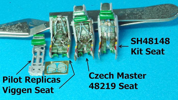
There is a growing after-market for this kit for those who want to build the best VIggen representation available. I tried to add a few components and scratch build a few others to give me the model I wanted. I do recommend at a minimum that you consider replacing the kit plastic ejection seat with a resin component and add new resin wheels and the RAT unit which is always open on the Viggen when it lands and usually after the aircraft is first shut-down. Take a look at parts from Two Mikes Resin, Czech Master Resin, Maestro Models, Master Models brass and Pilot Replicas to add improved or let’s say enhanced detailing to your Viggen.
Initially I was prepared to throw away the Special Hobby kit ejection seat. After cutting it from the sprues and gluing it together I was unimpressed with its details. It has an accurate and acceptable outline in its bare plastic form but sitting next to an unpainted resin seat there is no comparison. I was stunned to see how good it can look once you paint it and add its kit etched parts. Clean up seams and gaps and properly paint, weather and add the excellent SH kit color etched parts and you are good to go.
When I first opened the kit and glued the ejection seat together I immediately ordered a resin replacement. Once I had the resin parts in hand, painted them all and weathered them I photographed them with the SH plastic kit seat. What I saw was you will be happy with all of the ejection seat alternatives which included a well painted kit plastic seat with the color etched parts. This means I strongly suggest you have a resin replacement for the Tarangus Viggen release since it is lacking in the color etched parts unless you add the Maestro Models color etch metal parts to the build. All the resin seats I bought looked great after paint and weathering.
For those addicted to seamless suckers or inlet areas the kit provides complete inlet trunking and a very hard to see turbine engine face. Eliminating this seam can be a concern. I chose to scratch build some FOD covers because many of the color photos I saw featured Viggens with their inlets plugged. This would be a nice resin or etched part that I would hope to see available soon – a FOD cover for the Viggen.
Cockpit detail is good and can be enhanced by the addition of color and brass photo-etched parts. At the time of this review there are no resin cockpit replacements, just resin ejection seats available to detail the cockpit area.
The landing gear are a kit by
themselves. The Viggen has a very complex main landing gear arrangement. It
is extremely well reproduced in the kit plastic. Be very careful when
assembling the pasts in this area and look closely at all three pages, read
it several times unless you were once a Viggen ground crew! The instructions
are very well done but can fail to communicate the exact positioning of
attachment points for some landing gear parts. After building one I saw some
mistakes and the second landing gear is more accurate so I caution you. The
landing gear is unlike most other plastic kits so years of experience does
 not count for an easier build. You will like the end results though because
it is a faithful and accurate reproduction of the landing gear. Some have
expressed concerns about a lack of detail in the landing gear bays. This is
a personal preference area and will probably be addressed by a resin
replacement in the future. I was not overly impressed with the details
inside the bays but comparted to the ESCI/Airfix release of many years ago
it looks better than that offering. I found it adequate and because the
landing gear are so well done it met my personal checklist of moving on and
leaving this area as is. For my taste the glass is half full here mainly
because the main landing gear doors close after the gear are lowered so you
don’t see as much of the detail on the actual aircraft in this area in a
static display.
not count for an easier build. You will like the end results though because
it is a faithful and accurate reproduction of the landing gear. Some have
expressed concerns about a lack of detail in the landing gear bays. This is
a personal preference area and will probably be addressed by a resin
replacement in the future. I was not overly impressed with the details
inside the bays but comparted to the ESCI/Airfix release of many years ago
it looks better than that offering. I found it adequate and because the
landing gear are so well done it met my personal checklist of moving on and
leaving this area as is. For my taste the glass is half full here mainly
because the main landing gear doors close after the gear are lowered so you
don’t see as much of the detail on the actual aircraft in this area in a
static display.
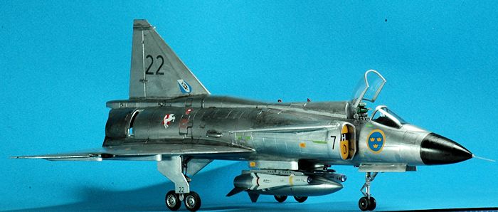
Two versions of drop tanks, accurate in outline are provided. No other ordnance comes with the kit. That turned out to be a blessing since it led me to using some Eduard Brassin resin for my ordnance and that was a beautiful modeling experience – kudos to Eduard on their entire Brassin product line – it is truly world class and an excellent value for the price. I will be using much more of it after this build. I was stunned by the details and complete, including stencil details, perfectly cast Brassin resin AGM-65 Maverick (Rb 75 version) that I used with this build. It was a beautiful modeling nirvana moment to open that package and add it to this build. It matched an ultra-definition (probably taken by a large format Hasselblad camera) color photo of AGM-65B’s (called Rb 75 in Sweden) hanging from a Viggen in a head on in-flight photo.
The kit decals are very well printed and similar to aftermarket in quality and thinness. The decal sheet includes many very nice stencils and small detail decals which add to the realism of your model. My only concern was once they are applied they refuse to move so be aware of this when you apply them. The color instruction booklet is very well done and makes decal application and painting much easier.
How does it compare with the ESCI/Revell/Airfix (all the same moulds) AJ 37 Viggen? I took a look at the ancient ESCI #4018 AJ 37 Viggen kit for comparison. The 1980s saw the only 1/48 scale Viggen kit introduced by ESCI, with two main boxing’s for the AJ and the JA variants.
As expected the Tarangus/Special Hobby kit is superior in all ways. I did notice that the ESCI centerline pylon assembly part 9B did include the strake between the ECS and dorsal fin. It looks like Tarangus/SH left this part off in order to accommodate use of the part for both the AJ 37 and JA 37 kits but forgot to include the "missing link" required in the AJ 37 connecting the ECS to the dorsal fin. The ESCI kit ejection seat has the wrong type of ejection seat firing handles using something that looks like the Martin-Baker F-4 Phantom II seat handles with face curtain – totally wrong. In other respects the rest of the seat is also wrong in shape. There is no cockpit detail - everything is a flat surface with decals providing an illusion of instruments. ESCI missed the increased length of the JA 37 vs AJ 37 requiring an aftermarket fuselage plug but Tarangus has it on their JA 37 parts sprue.
The ESCI kit does however provide for the four intake struts (part 16B) for the upper and lower areas separating the fuselage from the air intakes. The Tarangus/SH kit only provided two intake struts for the upper section. The ESCI kit is missing the three thrust reverser petals. The Tarangus/SH kit has a very accurate, and highly detailed landing gear assembly while the ESCI is so simplified that it approaches a toy with little detail. The ESCI kit has raised panel lines, with very poor details in areas such as the cockpits and undercarriage, and many mistakes all over the airframes.
As ESCI went out of business
in the early 1990s, those kits became a coveted release and until the
 Tarangus/SH release were becoming very difficult and expensive to find. As
with many other ESCI moulds, the Viggen kit was re-boxed under the Airfix
label. As a coincidence, a very nice pair of decal sheets were put on the
market from Two Bobs, following the hard to find decal from Flying Colours
which only covered the double-grey low-viz camouflaged JA-37.
Tarangus/SH release were becoming very difficult and expensive to find. As
with many other ESCI moulds, the Viggen kit was re-boxed under the Airfix
label. As a coincidence, a very nice pair of decal sheets were put on the
market from Two Bobs, following the hard to find decal from Flying Colours
which only covered the double-grey low-viz camouflaged JA-37.
A large selection of aftermarket resin and etched detail sets were issued to address all the deficiencies of the ESCI mould. Disintermediation in the form of the Tarangus/Special Hobby kit release makes using the ESCI/Airfix kit an expensive nostalgic kit build. If you still want to build your ESCI kit think about adding these aftermarket upgrades - Maestro airbrakes, Maestro corrected canopy, Maestro ejection seat, Maestro m/70 rocket pods, Maestro RAT (Ram Air Turbine), Master Models brass Viggen pitot tube & AOA, Two Mikes corrected nose, Two Mikes corrected belly, Two Mikes intakes, and Two Mikes canards. Maybe this is why we have not seen many ESCI Viggens built!
| CONSTRUCTION |
I started my construction by taking a look at a few builds on the web and thoroughly reading two outstanding reference books, The Saab 37 Viggen Walk Around, by Mikhail Putnikov, Squadron Books #25055 released in 2013 and Nordic Airpower #5 Saab 37 Viggen – The Ultimate Portfolio released in 2014. I made some notes on details I noticed in these references versus kit plastic and followed the kit instructions. A fantastic modeler, Pierpaolo Maglio, was very kind in providing helpful advice and sharing his knowledge of the Saab Viggen before I started. That was a huge help to have him share his thoughts. He loves the subject and has superb modeling skills to the point of being the master pattern maker of many of the correction resin parts you see or will see in the future. I really don’t know much about this aircraft so I do not hold myself out to be an “experten”. I know some more now after my kit build but I am still on the learning curve when it comes to the Viggen.
There are a few errors in the instructions caused by using basically the same instruction manual and sequence for both the Tarangus and Special Hobby releases. The AJ 37 is not the same aircraft as the JA 37. While that seems to be a “so what” statement it does mean when a kit manufacturer tries to combine two version in a universal kit by adding the “extra” bits needed for one version versus the other the instructions must be correct. The instructions are otherwise excellent, printed in color on glossy paper and a first class effort. However, with my limited knowledge and desire to build an accurate model I think I found some concerns with a few missing details.
 The build starts with the
cockpit. The ejection seat is elaborate once you take into account the
number of small etched metal details that are required. I layered them on
after first giving a lot of thought to what sequence to use so the end
turned out as planned. The first three steps are just for the ejection seat.
The big benefit of using the kit plastic ejection seat with its color etched
is – it fits! The Czech Master Resin seat that I used for this build looks
very nice and also fit. Some of the other resin seats require removal of
material at the bottom, or surgery to the kit plastic cockpit part 201A tub
because the kit plastic tub has a smaller bottom to the tub that the top
area whereas the resin seats are not as tapered (except for Czech Master’s
which did have a smaller footprint and did fit). After painting with Gunze
Aqueous H308 grey I added the kit etched cockpit placards. It looked very
nice once completed. If you are a good detail painter and weather type you
will get a fine cockpit with the kit plastic parts.
The build starts with the
cockpit. The ejection seat is elaborate once you take into account the
number of small etched metal details that are required. I layered them on
after first giving a lot of thought to what sequence to use so the end
turned out as planned. The first three steps are just for the ejection seat.
The big benefit of using the kit plastic ejection seat with its color etched
is – it fits! The Czech Master Resin seat that I used for this build looks
very nice and also fit. Some of the other resin seats require removal of
material at the bottom, or surgery to the kit plastic cockpit part 201A tub
because the kit plastic tub has a smaller bottom to the tub that the top
area whereas the resin seats are not as tapered (except for Czech Master’s
which did have a smaller footprint and did fit). After painting with Gunze
Aqueous H308 grey I added the kit etched cockpit placards. It looked very
nice once completed. If you are a good detail painter and weather type you
will get a fine cockpit with the kit plastic parts.
In step seven (7) I suggest you add part # 204 after the ejection seat is installed. It is a very tight fit and adding it at the point indicated in the instructions will not allow the ejection seat to fit or cause a very bad gap when you try to close the two fuselage halves because the seat will press against the part #204 glued in the wrong spot on your fuselage sidewall. There is room and it is easy to add after the cockpit tub and fuselage half are put together. It may not be a problem if you use the kit plastic ejection seat but the better side details on a resin ejection seat cause a non-fit issue if you go the after-market route on the ejection seat.
Step eleven (11) is for assembling the afterburner and engine exhaust outlet. Despite an “info 121 - orientation” warning I could not, based on the instruction booklet diagram, determine by looking at the part which way to use it. The issue for me was the “orientation” diagram versus the kit plastic details. It would have been far better for MPM to have designed or engineered a tab for alignment in this area. This is an important area because the thrust reverser has to be properly attached so the forward outlet is properly aligned. I first painted all the parts and let them dry. My approach was to take the kit fuselage parts held together by tape, parts 103 and 104 and place the burner can part 121 with part 122 already glued to #121 inside the fuselage halves. I rotated them until the open area was where it should be and glued them onto part 104. I glued the thrust reversers, parts # 123, which I first painted with Testors metalizer exhaust color, onto the inside of part #107 which is the rear of the exhaust section. There are indentations indicating where they go. The thrust reversers are usually found with the top petal down and the two lower petals flat against the side of the exhaust can. I glued the three parts #123 onto part 107. Then I attached this to the part 121/122 which was already glued to one fuselage half.
Step twelve (12) is the joining of the front fuselage/cockpit section to the rear fuselage sides and exhaust area combination from step 11. This does not work as advertised. The fuselage spine on part 101 is too long. There is a “cut-here” line on the inside but it is not called-out nor part of the instructions. Perhaps there was an intentional stretch to acknowledge that the JA 37 is longer than the AJ 37. In order to accommodate the larger jet engine the fuselage was stretched in front of the wing on the actual aircraft. So maybe to reflect this the incremental length was built in to a JA 37 part which needed to be cut-down to make the AJ 37 correct fuselage spine? Once I cut it all the parts mated and my assembly continued.
| COLORS & MARKINGS |
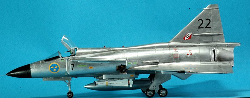
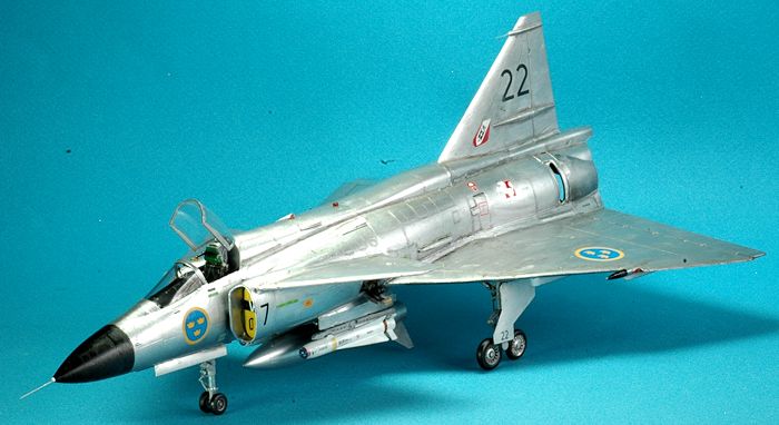
I used AK Interactive metallics for the overall natural metal finish (NMF). No sealing coat was applied over the NMF. I did polish it with SNJ chrome polishing powder and used a burnt umber oil paint wash to highlight panel detail. I first painted the cockpit with Gunze Aqueous H308 Gray FS36375 as well as the landing gear and landing bays. An artist’s oil burnt umber wash was also applied to the CMK Czech Master’s resin seat and Two Mikes #148001 resin wheels.
I used the kit decals
representing AJ 37 #7-22., S/N 37022, call sign Gustav 22, F7 Wing, from
Satenas, Sweden, in 1973. During a visit to Buchel in West Germany, where an
air show took place on September 1973, squ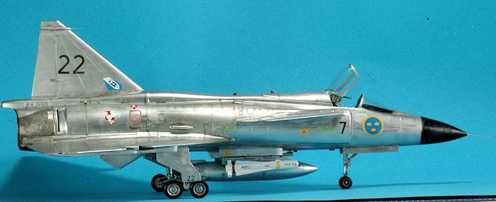 adron badges for Luftwaffe units
JBG 33 and JBG 36 were applied to this airframe. The decals were thin and as
good as most after-market decals going on well but requiring care in
application since they had a tendency to stick and become immovable once
applied. Five excellent reference photos for AJ 37 #7-22, S/N 37022, when it
was with the F7 Wing, in Satenas, Sweden, in September 1973, are in Nordic
Airpower #5 Saab 37 Viggen – The Ultimate Portfolio, on page 28. In early
1974 the Swedish Flygvapnet introduced the splinter camouflage on the Viggen
and the NMF era ended.
adron badges for Luftwaffe units
JBG 33 and JBG 36 were applied to this airframe. The decals were thin and as
good as most after-market decals going on well but requiring care in
application since they had a tendency to stick and become immovable once
applied. Five excellent reference photos for AJ 37 #7-22, S/N 37022, when it
was with the F7 Wing, in Satenas, Sweden, in September 1973, are in Nordic
Airpower #5 Saab 37 Viggen – The Ultimate Portfolio, on page 28. In early
1974 the Swedish Flygvapnet introduced the splinter camouflage on the Viggen
and the NMF era ended.
On the Eduard Brassin AGM-65B Maverick ordnance I painted them with Gunze Aqueous H11 White and used Gunze H93 Clear Blue on the transparent nose. Although the instructions indicate using a Clear Yellow or Orange paint on the nose piece which would be correct for the AGM-65B I chose the blue color to mimic the cover photo on the Nordic Airpower # 5 book which features a head-on picture of the Saab 37 Viggen carrying four Mavericks featuring a very clearly seen blue / grey nose tip. I can’t argue with photo evidence and it could also be an AGM-65E which does have a blue / grey nose tip. The AGM-65 Brassin product also includes a detailed launch rail – fantastic inclusion and required to get this part right on most models including the Tarangus/SH Viggen’s. The Walk Around text has a weapon loading scheme on page 24 to validate your use of any ordnance and its placement on the correct pylon.
I can’t say enough nice things about the Eduard AGM-65 Brassin Maverick. It looked better in my hands than the 3D CAD drawings Eduard used to introduce the product! It is a lovely little model by itself and added a great deal to my model. I only wish they had cast the fuselage and rear section in one instead of two parts. Maybe it was #D printed which would cause the need for two parts. The two part approach requires great care in sanding to permit an accurate alignment of the two sections and a gap between the two joins as well requiring some filler. I used AVES Apoxie Sculpt to fill in the slight gap on parts of the join because it permitted me to use water and a metal sculpting tool to smooth the gap area eliminating any very difficult sanding task. I also used AVES Apoxie Sculpt on any gaps on the entire model using the same water and tool technique to smooth areas rather than sanding down the hardened material with its subsequent loss of details. Easier, faster, better! To be 100% correct you might want to add custom stencils for the Swedish version of the Maverick such as “RB 75” which was their term for this ordnance in Swedish use.
I noticed a brownish discoloration on the rear tail section around the exhaust area probably caused by engine heat similar to that found on the F-100 Super Sabre tails. I used some Testors metalizer and burnt umber oil parts on this area. Also, you might want to paint the underside speed brakes a reddish-brown color to simulate the composite “Textolite” material which were left unpainted. This was replaced by a silver colored glass composite which had a better stress cracking resistance so I left mine painted in NMF silver.
| FINAL CONSTRUCTION |
A few other problems came to light during construction. Some I dealt with; others were intentionally neglected. There may be many more for all I know because my knowledge of the Viggen is quite limited, but this is what I suggest you consider when building this kit. I used a number of after-market parts and some scratch building additions for this build in addition to some parts fixes.
 After hearing from
knowledgeable Viggen types and getting sage advice from those who know much
more than I about the Viggen, I added a resin ejection seat from CMK Czech
Masters #48219, Two Mikes #148001 resin wheels, a Pilot Replicas RAT (Ram
Air Turbine) unit and Master Model brass pitot, Angle of Attack (AOA) sensor
probe AM-48-074. The AOA sensor probe was totally missed on this kit. Clear
photos of the AOA can be seen on pages 1, 15 and 34. Sometimes you will see
the AOA probe covered by a black box with a bright yellow cross to ensure it
gets removed before flight.
After hearing from
knowledgeable Viggen types and getting sage advice from those who know much
more than I about the Viggen, I added a resin ejection seat from CMK Czech
Masters #48219, Two Mikes #148001 resin wheels, a Pilot Replicas RAT (Ram
Air Turbine) unit and Master Model brass pitot, Angle of Attack (AOA) sensor
probe AM-48-074. The AOA sensor probe was totally missed on this kit. Clear
photos of the AOA can be seen on pages 1, 15 and 34. Sometimes you will see
the AOA probe covered by a black box with a bright yellow cross to ensure it
gets removed before flight.
There is a missing extension to the center pylon strake (part 170) where the droppable fuel tank is attached. The center strake should extend back and be connected to the dorsal fin (part 125). A replacement center strake will be available from Maestro. This oversight occurred because Tarangus engineered the JA 37 underbelly gun to attach to the ECS and form a correct segment in front of the dorsal fin. It looks like they "forgot" to provide the part required for the AJ 37 when there is no 30mm Oerlikon KCA m/75 belly gun which is only on the JA 37.
The Environmental Conditioning System (ECS) portrayed by parts 161+162 in step 24, that provides air for heating, cooling, pressurization of the cockpit, and the avionics bay has a center splitter plate. This divider is missing. I added some plastic strip as a divider. A very clear picture of this can be seen on page 20 of the Walk Around text. Pierpaolo Maglio suggested this fix: “the ECS intake is upside down for the AJ 37, it is correct for the JA 37, but for modeling the AJ you must cut the front part by 2.3 mm and glue it upside down, then add putty and sand flush, then you can add the center splitter plate.”
Step 3 in the instructions has you placing all the etched straps and buckles on the plastic kit seat. The two part PE13’s are the wrong color. They should be blue/gray and not olive drab in order to match etched part PE4/PE5 colors.
Step 11 has you placing the thrust reverser petals into the after burner area (i.e. “reheat”). You have a choice here of using after-market resin petals from CMK as I did or using the kit parts # 123 instead. I drilled out the holes in the kit plastic for a comparison and the CMK part (#48-222) is slightly better and fits very well. Note, the top center petal droops down and stays in that position when the engine shuts down and hydraulic pressure drops to zero. The other two petals remain retracted at engine shutdown. See color photos of the petals on page 22 and 37 in the Walk Around book. The kit plastic looks fine and as a friend commented no one is looking up the dark exhaust area so maybe it’s not needed. Hmm, I have seen a number of flashlight wielding bandits who do enjoy doing a plastic kit rectal examination so the choice is up to you. This one is a toss-up. Keep in mind the thrust reverser petals on ground could stay in 2 ways: all 3 fully closed or just the top one closed, i.e. pointing down, and the two lower ones fully opened. This is due to the lack of engine hydraulic pressure when the engine is shut down.
There are four support bars bridging the gap between the fuselage and air inlets, parts 141 + 142. The kit only provides two for the top area. The actual aircraft has four of these so the two needed on the bottom should be added. This looks like a scratch build option for you.
Initially I thought the nose probe was “OK” but after seeing a comparison photo by Pierpaolo Maglio the Master Models brass parts are an order of magnitude better, stronger and includes the AOA probe and vertical tail fin probe as well replacing the oversized probe on the tail. It is a must add!! My best Viggen expert, Pierpaolo Maglio felt: ”The kit nose probe is a SHAME! WAY too BIG! Probably the worst part of the kit.” So be forewarned. I used the Master brass replacement – you should too!
Many photos of the Viggen on the ground show FOD plugs on the intakes. They are painted a variety of colors and usually in an all yellow or black and yellow striped color as an ease of visibility “remove before flight” reminder. I scratch built mine and found an easy way to do them was to tape a piece of thick Evergreen styrene plastic to the bottom of the air inlet parts 141 + 142 and hand paint a small amount of acrylic inside on the taped Evergreen part. Once dry I removed the plastic and cut around the unpainted area with some plastic sprue snippers. You must leave some room because the inlets taper and in order for the FOD plug to fit it needs to be larger than the bottom of the inlets. I guess you can reverse my process and use the forward area of the inlet but I did not want to have any hard to remove paint on a NMF inlet tip. The bottom part is easier to clean up. I used a metal file to work down the edges, constantly dry fitting to get it just right. It worked well for me and I prefer this than fixing the seams in the trunk area. I also prefer the look. You will see a number of FOD covers on the inlets on the airframes seen in the two recommended reference texts I used.
Clear parts # 909 are
worthy of further research. The instructions have you paint them
red/green depending on the side. These are very tiny clear plastic
parts. The parts were changed on the later Viggen, the JA 37 but this is
not reflected on the Tarangus instructions. See page 63 in the Walk
Around book for a close up of this part and page 157 of Nordic Airpower
as well. The rear section of the light has a clear lens on the JA 37. I
think the rear light is only facing backwards and has a white bulb in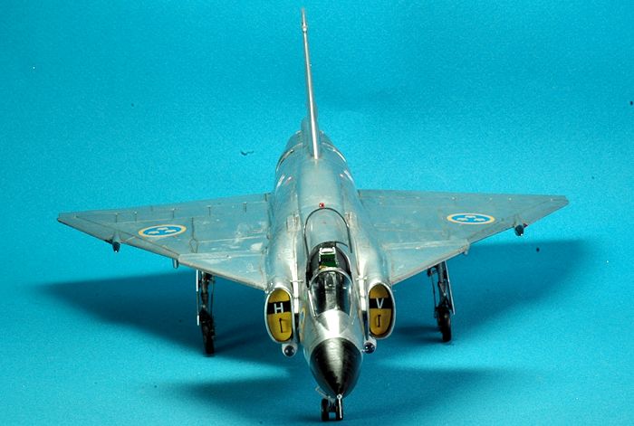 the AJ 37.
Color Ejection Seats on pages 18-19 and color cockpits on pages 16, 32, 33, 55, 66, 67 for both the AJ 37 and JA 37 are found in the Walk Around – as I said this is a must have reference.
Steps 19a & 19B show the landing light part # 906 placement. The instructions would have you place two of them, side by side inside the front landing gear wheel bay. This is correct but one other light is missing. There is a landing light on the landing gear strut just above the scissor link which is missing in the instructions and from the clear parts tree. I took one of the part # 906 lights and placed it just above the link and on the strut. I found a perfect reference photo for this question at the IPMS Sweden web site: ipmsstockholm.se in a reference story by Martin Waligorski with color photos also by Martin Waligorski titled "My Viggen story". Yes, there are three landing lights in the front wheel bay area. I thought I saw this in one photo of a Viggen on its landing approach it did look this way and there are three lights.
Step 23 appears to be left over from the Tarangus JA 37 instructions. On the underside of the wing the later JA 37 has a fourth strake, parts 111 + 112 added. The AJ 37 did not have these extra strakes so do not add them as the instructions recommend.
Step 31 has a “use a part from step 30 here”. I think it is wrong and you should use parts 154 + 156 from step 29. Step 33 has a “use a part from step 29 here”. I think it is wrong and you should use parts 154 + 156 from step 30. My basis for this is they are two different sizes and the kit plastic fuselage has an indentation corresponding to the size differences. So before you glue them in place, match them to the appropriately sized indentations. The parts look alike but are in fact two different sizes and you can see this in Nordic Airpower # 5, page 157.
You can glue or attach the two main gear doors 137 + 138 hanging down. I did not because they do not droop or appear opened up when the aircraft is on the ground unless this area is exposed for maintenance work. So I removed the four tabs and glued this shut. As Pierpaolo Maglio stated “Only in museums are these left opened for security reasons”.
If you want to get one of those small detail items right see the PN-865/A transponder, part 147 and the clear beacon part 911 in a clear close-up area photo on page 31 of the Walk Around text. The instructions would have you glue these on before painting the airframe. I left them off and added them in the final steps, after the airframe was painted.
Step 33 would have you attach part # 124, a VHF antenna. This is wrong for the AJ 37. It is only used in the JA 37 (i.e. the Tarangus kit).
Some would wish to detail the glass HUD by adding a more realistic frame. You can scratch build this out of plastic strips. I think it should have been on the etched metal fret.
If you choose to model using the splinter green camouflage which was the prevalent color scheme for most Viggens I highly recommend using the Maestro Viggen paint masks. Pierpaolo Maglio noted “Yes, it is well made but studied to fit the longer fuselage JA 37 so some adjustments are needed for the AJ 37.”
One thought on the “size difference” between the AJ 37 and JA 37. The AJ 37 is 16.30 meters (53.477 feet) according to page 12 of the Walk Around text. The JA 37 is 16.40 meters (53.805 feet) according to page 68 of the Walk Around text. Thus the .1 meter or 0.328084 feet or 3.937 inches in increased length would be 0.082 inches in 1/48th scale. That’s too small of an increment for me to be concerned with any size difference expectations in the kit plastic.
The three etched metal mirrors were enhanced by using some plastic film aluminized interior surface food wrapping material. This is found on the inside surface on potato chip or Keebler Vienna Fingers cookies wrapping (it is a vanilla flavored cookie). I glued the shiny inside part of the wrapper to the three etched metal mirrors surfaces fading the ejection seats. I like how this looks. The kit instructions failed to properly identify and help with the addition of these parts and a few other etched metal parts. The mirrors are attached to part 904, the front fuselage windscreen and not to the main canopy as in some jets.
I added a Radar Warning Receiver (RWR) to the area below the tail at the end of the fuselage extension to the tail fin fairing. See page 37 Walk Around text. This is missing from both the Tarangus and Special Hobby kits or what is there is a very small for all version raised line box shaped. The AJ 37 has a light gray colored triangular shaped box. The JA 37 has an updated RWR which is a round or ball shaped RWR with two 45 degree protruding sensor stubs – see photo on page 72 of the Walk Around book. It is an easy fix by shaping some sprue.
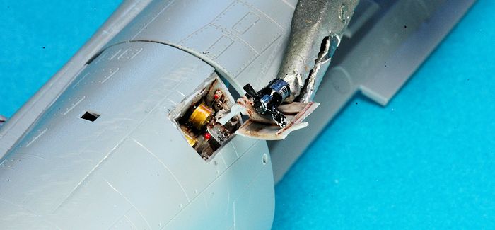
Do you need a RAT? The kit does not provide any
Ram Air Turbine (RAT). Hasegawa’s Draken for example does have a RAT in
recognition this is a very visible component of modern Swedish aircraft.
I highly recommend you add the Pilot Replicas Viggen RAT resin
enhancement product. It is extremely accurate and well done. I added
Mike Grant decals, CKP048 dials to the panel inside the RAT unit. You
can easily also use the 1/72nd scale sheet, # CK072 since
these dials are small. The RAT generator has a silver product
information plate with black lettering you should apply from the Mike
Grant sheet as well. I painted the two round devices with Tamiya Acrylic
Paint Titanium Silver (X-32) and when it was dry used a thinned coat of
Gunze Clear Yellow to get the metallic yellow finish found on those
drums. The RAT can be seen extended when the aircraft is landing as wel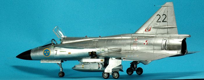 l
as when it is on the ground. See Nordic Airpower 5, on pages 24, 25 and
26. A very clear photo of the RAT unit close up are found in the Walk
Around on page 41.
l
as when it is on the ground. See Nordic Airpower 5, on pages 24, 25 and
26. A very clear photo of the RAT unit close up are found in the Walk
Around on page 41.
The Viggen landing gear is quite complicated and very faithfully reproduced in the Tarangus/Special Hobby kit plastic. I highly recommend you look at the Walk Around book, pages 42 through 45 for an understanding of what the components look like, their colors and placement before you use the kit instructions and start assembly of this area. Some of the instruction diagrams may be misleading regarding where parts actually go. You almost need a 3D CAD rotating view of the part to appreciate how it goes together and how good the kit parts are. If you have any mistakes I would not blame the kit! The Viggen main gears are so complicated your normal approach of cutting and gluing landing gear parts may not work.
Some additional fixes suggested by Pierpaolo Maglio are found on his Facebook page. In summary they are: Fill in the square depression seen on the fuselage after the exhaust exit from the thrust reversers with plastic card. He scribed a new inspection panel further to the rear. IFF antennas must be scratch-built and added to the underside of the fuselage just after the main dorsal fin.
| CONCLUSIONS |
I like the Tarangus/Special Hobby Viggen. Yes, it is a bit pricey but I thought it worth getting and am glad I have it, built it, and it’s on the display shelf unlike the ESCI/Airfix releases that still sit in my stash. If you look at prior Viggen offerings and the cost of resin correction sets the price is not too bad. If you build the Tarangus release I recommend you get the Maestro color etched parts. The Tarangus release instructions do call out the parts unique to the JA 37 versus this kit I built, the AJ 37 sold by Special Hobby. There is a difference in the airframes and you will enjoy building both as I have.
The kit in its plain OOB mode or with lots of aftermarket is sure to please most of us. I hope the list of fixes and changes and recommendations don’t intimidate you from building this kit. Overall it was not a hard build. Just take your time, file off any sprue stubs for a clean fit because it is a precision molded plastic kit and not the crude limited-run moldings of yesteryear. The decals were superb and with several choices in markings there is no reason not to build several of these.
| REFERENCES |
SAAB 37 Viggen" by Paul Jackson, WORLD AIR POWER JOURNAL, Volume 13 / Summer 1993, 46:89
SAAB's Classic Canard" by Malcolm English, AIR INTERNATIONAL, February 1999, 91:102
"SAAB Sk 37E Stoer-Viggen" by Jan Joergensen, WORLD AIR POWER JOURNAL, Volume 42 / Fall 2000, 24:26.
"SAAB 37 Viggen" by David Donald, INTERNATIONAL AIR POWER REVIEW, Volume 14 / 2004, 44:75.
Saab 37 Viggen Walk Around by Mikhail Putnikov Squadron Books #25055 2013
Nordic Airpower #5 Saab 37 Viggen – The Ultimate Portfolio 2014
Andrew
Garcia November 2015 Copyright ModelingMadness.com
If you would like your product reviewed fairly and fairly quickly, please contact the editor or see other details in the Note to Contributors.