|
KIT: |
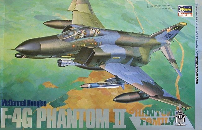
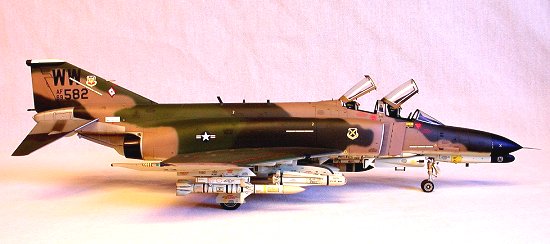
Hasegawa 1/48 F-4G Phantom II |
|
KIT # |
P 4 |
|
PRICE: |
$24.00 (in 1984) |
|
DECALS: |
One aircraft |
|
REVIEW & |
|
|
NOTES: |
|
|
HISTORY |
Anyone with more that a passing interest in military aviation would have to have been freeze-dried for the last forty years not to have a modicum of knowledge regarding McDonnell-Douglas's ubiquitous F-4 Phantom II. Therefore, a full in-depth historical treatise is not warranted here. The Wild Weasel variant, however, was a special version specifically tailored for the air defense suppression role. Thus, some background is in order.
During the early stages of the air offensive against targets in North Vietnam, USAF combat aircraft found themselves face to face with the threat of radar-guided surface-to-air missiles (SAM's), eagerly provided by the Soviet Union. It was not totally unexpected as US forces had confronted the SAM threat before (witness the May Day, 1960 shootdown of Francis Powers' U-2 and several incidents during the Cuban missile crisis).
 USAF tactical planners scrambled to field a missile suppression
platform which, suitably modified, could escort strike aircraft into the more dangerous route packages north of Vietnam's nebulous DMZ. The
aircraft selected was North American Aviation's two-seat F-100F. Though modestly successful, this aircraft had several shortcomings. Limited
USAF tactical planners scrambled to field a missile suppression
platform which, suitably modified, could escort strike aircraft into the more dangerous route packages north of Vietnam's nebulous DMZ. The
aircraft selected was North American Aviation's two-seat F-100F. Though modestly successful, this aircraft had several shortcomings. Limited
interior volume restricted the growth potential of the airframe (vis-à-vis avionics countermeasures upgrades), ordnance capability was
limited, and most damning of all, the plane simply could not keep up with the strike aircraft (most of which by this time were F-105 Thunderchiefs)
once they had dropped their bombs.
The remedy was fairly obvious. The Air Force had some two hundred F-105F two-seaters on strength for use as combat crew trainers. These were modified with advanced combat capabilities under Phase II of the Wild Weasel program. Phase III was an extensive enhancement of the existing F-105F airframes resulting in a new designation--the F-105G. These aircraft performed admirably through the end of the Vietnam War and beyond.
Prior to the war's end, Air Force planners became concerned about the
viability of the Wild Weasel force. Combat attrition levels for all F-105 units had been high (over 400 aircraft lost) and most surviving
Thunderchiefs would eventually be transferred to Reserve and Air National Guard units. Meanwhile, Tactical Air Command (TAC), eager to streamline
and standardize its force both tactically and logistically, selected the F-4 as its new Wild Weasel aircraft.
Under Phase IV, F-4C's were modified for the mission with the first
aircraft delivered in the summer of 1969. Teething problems plagued the program and the first F-4C Wild Weasel combat sorties did not occur until
October of that year. Visually, the aircraft were distinguishable by a number of additional antennas and fairings on the nose and tail, pylon
adapters on wing stations 2 and 8 to allow carriage and launch of the AGM-45 Shrike missile and deletion of the AIM-7 Sparrow missile
capability. Thirty-six were built.
The Air Force, with an eye on growth potential, wisely decided that
the ultimate Weasel could only be achieved by starting with a gutted F-4E airframe. This offered the advantages of increased interior volume (with
the M-61cannon removed), increased range (due to the F-4E's extra fuselage fuel cell), ease of maintenance (F-4E's had mostly solid-state
avionics), and the tactical advantage of up-rated GE J-79 engines (smokeless) and the slatted wing (a must-have for in-the-weeds yanking
and banking). This new Weasel was designated as the F-4G.
 Unlike the earlier F-4C Wild Weasel, the new Phase V aircraft
retained full Sparrow capability while adding the AGM-78 (Standard ARM), AGM-88 (HARM), and AGM-65 (Maverick) to its roster of certified missile
ordnance. AGM-45 Shrikes could also be carried though dwindling stocks of this 35 year-old missile make this event a rarity. Visually, the F-4G resembled the F-4E in most respects. The most
noticeable differences were the forward APR-38 receiver fairing which replaced the muzzle brake for the removed Gatling gun, and the rear
APR-38 receiver fairing on top of the vertical fin. Several smaller
Unlike the earlier F-4C Wild Weasel, the new Phase V aircraft
retained full Sparrow capability while adding the AGM-78 (Standard ARM), AGM-88 (HARM), and AGM-65 (Maverick) to its roster of certified missile
ordnance. AGM-45 Shrikes could also be carried though dwindling stocks of this 35 year-old missile make this event a rarity. Visually, the F-4G resembled the F-4E in most respects. The most
noticeable differences were the forward APR-38 receiver fairing which replaced the muzzle brake for the removed Gatling gun, and the rear
APR-38 receiver fairing on top of the vertical fin. Several smaller
antennas were located ventrally foward of the nose gear fairing, on the fuselage near the windscreen and on the spine, on the vertical fin, and
on the drag chute door.
F-4G's served with distinction from 1978 through the end of the Gulf War, when they were subsequently retired from service with the draw-down of US forces following the end of the Cold War. All surviving airframes were sent to Davis-Monthan AFB to await the breaker's torch. 116 were built.
(Editor's note: As of 5 October, 2000, there were 11 F-4G airframes at AMARC. Most of the rest have been converted to QF-4Gs with a few others being sent to museums or used as gate guards.)
|
THE KIT |
Hasegawa's F-4G kit consists of 124 light grey parts molded on eight sprues, 11 clear parts on a single sprue, a large comprehensive decal sheet, an eight-step instruction pamphlet, and a color photo plate featuring a built-up model with additional painting notes. Specified colors are geared to Gunze Sangyo paints but FS numbers are identified for conversion to other manufacturers.
All parts are relatively flash-free with minimal tooling marks and sink holes in evidence. Clear parts are prototypically Hasegawa--that is, thin and distortion-free. Surface detail is, for the most part, recessed with raised details in proper relief where appropriate. As this kit shares several common sprue trees with other Hasegawa F-4 releases, many parts will not be used for the Wild Weasel.
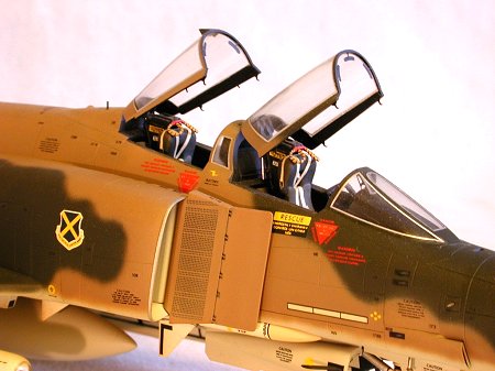
The cockpit consists of two 5-part seats and an 8-part cockpit tub. Two seated pilot figures are included. Instrument panels and side
consoles feature raised relief details with throttles conspicuously
absent from both crew stations. A skillful paint job and a few
aftermarket goodies will go a long way toward animating this otherwise
spartan assembly.
The landing gear is well-depicted with separate retraction jacks on
all struts and casting detail on the inner faces of all doors. Wheel hub
and brake rotor detail, while not totally correct, is acceptable.
Separate speed brakes allow the option of posing them in the deployed
position. The arresting hook is separate as well, allowing for the same
option.
 The wing features separate leading edge slats and partially-open
auxillary intake doors on the ventral side adjacent to the engines, while
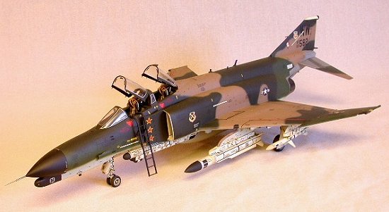
the stabilator is of the proper slotted type. An 11-part boarding ladder
is included for those inclined to dioramas.
The intakes are molded in six pieces (three per side) with the
variable ramp assembly (parts D27 and D28) separate from the inner face
of the duct. This allows for installation of the ramp after painting the
fuselage adjacent to the intake duct. A caveat is in order here--parts
D32 and D33 are molded hollow on the inside face. This concave area
should be filled prior to attachment to the fuselage. The area is quite
visible when assembled and painted, and the hollow molding will destroyany illusion of realism if left uncorrected.
The wing features separate leading edge slats and partially-open
auxillary intake doors on the ventral side adjacent to the engines, while
the stabilator is of the proper slotted type. An 11-part boarding ladder
is included for those inclined to dioramas.
The intakes are molded in six pieces (three per side) with the
variable ramp assembly (parts D27 and D28) separate from the inner face
of the duct. This allows for installation of the ramp after painting the
fuselage adjacent to the intake duct. A caveat is in order here--parts
D32 and D33 are molded hollow on the inside face. This concave area
should be filled prior to attachment to the fuselage. The area is quite
visible when assembled and painted, and the hollow molding will destroyany illusion of realism if left uncorrected.
Underwing stores and ordnance consist of two 370 gallon wing tanks, a 600 gallon centerline tank, an ALQ-119(V) ECM pod, AGM-45 and -78 missiles (one of each) with pylon adapters, four AIM-9J/P Sidewinder missiles with launch rails, and four AIM-7E/F Sparrow missiles. Some of these components need reworking to make them usable. For example, the 370 gallon wing tanks are too pointed at both ends while details on all missiles are rather soft and murky.
Decals are the standard-issue Hasegawa variety--that is, thick-appearing on the backing sheet, well-printed and on-register, and
slightly translucent. The specific aircraft featured are 69-208, "City
of Victorville--Sweet Sixteen" of the 35th TFW in standard SEA
camouflage, and 69-274 from the 561st TFS, 35th TFW sporting the
wraparound Euro 1 scheme.
|
CONSTRUCTION |
Construction of this model began with the wing. After some minor tweaks to the locating pins, I tacked the upper wings to the lower wing with small drops of Crazy Glue. After checking the assembly for any unwanted camber or dihedral problems (virtually uncorrectable once seams are fully glued with CA-type adhesives), I hard-glued all mating surfaces with Gap Filling Hot Stuff. When this adhesive had fully cured, I cleaned and dressed the seams then rescribed any surface detail lost during sanding.
 I like to install wing pylons, drop tanks, and anything else
that hangs with brass wire pegs and sockets fabricated from K & S aluminum
tubing, obviating the need for glue. Accordingly, I drilled all the mounting
holes out on the underside of the wing and glued short lengths of 1/16"
aluminum tubing in each hole with Crazy Glue. When dry, the excess tubing was
sanded off flush with the wing.
I like to install wing pylons, drop tanks, and anything else
that hangs with brass wire pegs and sockets fabricated from K & S aluminum
tubing, obviating the need for glue. Accordingly, I drilled all the mounting
holes out on the underside of the wing and glued short lengths of 1/16"
aluminum tubing in each hole with Crazy Glue. When dry, the excess tubing was
sanded off flush with the wing.
All pylons were cleaned up, rescribed where necessary, then had their plastic mounting pegs removed via razor saw. Using a pair of engineer’s dividers, I carefully measured the center-to-center distance of each pair of wing sockets and transferred these dimensions to each respective pylon, using the removed forward peg’s location on each pylon as a datum point. With the locations properly marked, I drilled the two holes in each pylon and installed short lengths of .035" brass wire, de-burred at both ends and anchored into the pylons with Crazy Glue.
After drying, I test-fitted each pylon to its respective location on the wing. If each pair of sockets is parallel to its intended pair of pegs, whatever is installed there will simply self-jettison with predictably disastrous results (gravity being the operative factor). To avoid this, I bent each front peg slightly forward and each rear peg slightly aft, resulting in miniscule but significantly divergent angles relative to the mounting sockets. The objective here is to produce enough friction between the pegs and sockets to overcome the 1G effect of gravity. When I was satisfied with the pylon-to-wing fit, I turned my attention to the centerline fuel tank.
Sometime in the early 1980’s, the geniuses at McDonnell-Douglas discovered that the 600-gallon fuel tank used on the F-15 was more aerodynamically efficient when installed on an F-4 than the original purpose-designed teardrop-shaped gasbag. Accordingly, the kit-supplied 600-gallon unit was DXed in favor of an F-15 tank light-fingered from a spare Monogram kit. Pegs were installed on the tank a la the wing pylons while the rear anti-sway brace/bumper was fabricated from scrap plastic. A cast brass RR eyebolt was used for the shackle at the rear of the bumper.
 I was not altogether satisfied with the shape of the
wingtip-mounted RHAW antennas so I sanded them flat, notched each location with
a jeweler’s file, then installed new ones fabricated from preshaped sprue.
After sanding and fairing the new RHAW antennas to the adjacent areas, I notched
the front and rear of each wingtip and installed navigation lights made of red
and blue-green Lexan. After rough shaping with file and Flex-I-Grit I polished
them with a buffing wheel chucked into my Mototool, starting with Brasso and low
speed, then finishing with Bare Metal compound and Mach 1 on the Dremel.
I was not altogether satisfied with the shape of the
wingtip-mounted RHAW antennas so I sanded them flat, notched each location with
a jeweler’s file, then installed new ones fabricated from preshaped sprue.
After sanding and fairing the new RHAW antennas to the adjacent areas, I notched
the front and rear of each wingtip and installed navigation lights made of red
and blue-green Lexan. After rough shaping with file and Flex-I-Grit I polished
them with a buffing wheel chucked into my Mototool, starting with Brasso and low
speed, then finishing with Bare Metal compound and Mach 1 on the Dremel.
The outboard maneuvering slats were removed from the sprue, cleaned up and installed with Testor’s liquid cement. The relatively slow drying speed of this adhesive allowed ample fiddle time to insure proper symmetrical positioning and alignment.
I decided to install the speed brakes in the closed position and, after a quick clean up, I glued them into the wells with a small drop of gap-filling Hot Stuff. The slow set-up time allowed me to slide each part around in its well until a uniform amount of reveal around each door was achieved. With the wing complete, I turned my attention to the intakes.
As per the review comments, the reverse sides of parts D32 and D33 were filled with Evergreen .020" sheet stock attached with gap-filling Hot Stuff and sanded flush. The inside faces of the ducts (parts J2 and J3) had several ejector pin marks which were filled and sanded smooth, along with some nasty tooling marks. After sanding with progressively finer grits, I polished the inside of the ducts with Bare Metal compound. When done, I taped each duct to its respective ramp and drew a pattern for a baffle on thin card stock. I used black polystyrene sheet stock cut to the pattern’s shape for each baffle.
After numerous test-fits, I removed the baffles and sanded the fronts with 1000 grit 3M automotive film, then polished them with Turtle Wax and a buffing wheel. When they shone like black onyx, I set them aside and returned to the ducts.
I painted the ramps and inner duct faces with Testor’s gloss white, thinned 50% and low (20 PSI) pressure. Thus applied, orange peel was held to a minimum. After a week of drying time, I carefully scraped the paint off of all mating surfaces and glued each duct to its ramp with gap-filling CA. After curing, I sanded the seams out and rescribed any lost surface detail. The polished black baffles were then inserted into the completed ducts from the rear.
Though a snug fit, I wanted to ensure no light would be visible when viewing the model from the front. I carefully ran a bead of gap-filler around each baffle from the rear, while blowing gently to ventilate any fumes which might cause chlorosis to appear on the polished front sides of the baffles.
 The smooth white enamel of the ducts, in conjunction with the
reflective effect of the polished black baffles provide a convincing illusion of
depth without resorting to cast-resin ductwork (not available when this model
was built).
The smooth white enamel of the ducts, in conjunction with the
reflective effect of the polished black baffles provide a convincing illusion of
depth without resorting to cast-resin ductwork (not available when this model
was built).
I next turned my attention to the interior. The basic as-issued parts, though usable, are just that—basic. I added throttles to both cockpits and the EWO’s radar antenna control handle in the rear office. Various doodads were added to each seat with Model Technology providing the photo-etched buckle sets for the seat belts. Waldron Products rubber oxygen hoses completed the add-on portion of the operation. The cockpit components and seats were painted as per photographic references then assembled with Testor’s liquid cement. The grab ring assemblies (parts D7) are particularly fragile and were left off for later installation.
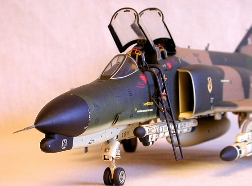
At this point, I taped the fuselage together along with the nose halves and inventoried the details, which needed refinement or structural beef-up. I fabricated a bullet-proof pitot tube from a slightly blunted chrome-plated sewing needle inserted into a short length of #20 transfusion needle. The nose pieces were assembled with Crazy Glue then sanded and rescribed to restore the panel lines. I drilled out the end of the radome, inserted a piece of 1/16" K & S aluminum tubing to serve as a receptacle for the pitot, glued it solidly with CA, then filed and sanded it to maintain the parabolic contours of the radome. The pitot tube itself would be installed later to facilitate ease of handling during the remainder of the assembly phase.
Two small vents at the lower rear of the fuselage which flank the claw portion of the arresting hook were drilled out to give them additional depth. The hook itself is somewhat soft in detail so I removed and replaced it with Monogram’s equivalent unit, razor-sawed from a spare F-4C fuselage. The up-lock assembly was detailed with pinheads, suitable reshaped and recontoured for their new mission.
On the right rear of the fuselage above the tailpipe is a small access door with a clear window. Inside the door is a pressure gauge for the hydraulic reservoir accumulator, which operates the arresting hook. I drilled out the window, squared the hole with a jeweler’s file, then filled the hole with a piece of clear sprue anchored with CA. After sanding and polishing both sides of the window, I applied a decal gauge on the inside surface, thus replicating this often overlooked detail.
At this point the cockpit and nose gear well were attached to the right fuselage and both halves mated together with gap-filling CA. After sanding and rescribing, the nose was added while I pondered the remainder of the mods and add-ons necessary. I drilled a small hole near the starboard A/C duct and installed a straight pin, point side out and slightly blunted, to serve as an AOA transducer. Below that, near the landing gear fairing I mounted a modified pinhead to serve as the outside air temperature probe.
 At the rear of the fuselage, I razor-sawed the fuel dump mast
off and installed a new one constructed of K & S aluminum tubing. 1/16"
was used for the trunk while a short piece of 3/32" was squashed into an
oval, beveled at both ends, and attached with gap-filling Hot Stuff to serve as
the diffuser.
At the rear of the fuselage, I razor-sawed the fuel dump mast
off and installed a new one constructed of K & S aluminum tubing. 1/16"
was used for the trunk while a short piece of 3/32" was squashed into an
oval, beveled at both ends, and attached with gap-filling Hot Stuff to serve as
the diffuser.
The drag chute door received two hemispheric RHAW antennas (which in actuality were dummies) fabricated from straight pins with domed heads. I also drilled out and cleaned up the D-shaped vent on the rear of the door. I notched the fin and installed the upper anti-collision beacon fabricated from red Lexan. The probe for the stability augmentation system was made from a ½" length of #20 transfusion needle set into a 1/16" aluminum socket installed in the leading edge of the fin.
Model Technology’s photo-etched F-4 canopy detail set fleshed out the cockpit along with some PE mirrors for the canopies themselves. New canopy actuators were scratch-built to replace the anemic kit-supplied parts. A faired exterior mirror from Monogram’s F-4C was installed on the wizzo’s canopy with white glue.
The final area of the fuselage to be addressed was the lame (and incorrectly located) attachment points for the stabilators. As engineered, Hasegawa provides short round pegs at the inboard chord of the stabs, which are inserted into holes at the rear of the fuselage. This method is not only structurally weak but will result in the stabilators being located too far aft by approximately 1.25 mm. I re-engineered the installation by mounting rectangular tabs (with the proper amount of anhedral) on both stabilators, cutting a properly located oversized slot in each side of the fuselage, then boxing in both slots with single strips of .010 Evergreen sheet stock passed completely through the fuselage. This resulted in a more structurally durable arrangement not unlike the method Testors/Italieri uses with their kit. The fit was, in fact, so tight that adhesive would not be required to attach the stabilators. This completed, it was time to start integrating the various sub-components into an airframe.
I attached the completed intake ducts with gap-filling CA. When dry the seams were sanded flush and panel lines rescribed. The Monogram arresting hook was notched at the hinge end to accept a .030" sheet stock tab, radiused at the pivot end. I drilled a 1/16" hole laterally through the rear fuselage (between the afterburner cans), and cut a .030 notch vertically through the keel. After inserting the hook’s tab into the keel’s slot, I stuck a small center punch into each of the holes and marked the locations on the tab. The hook was removed and a 1/16" hole drilled through the tab at the appropriate location. I re-inserted the hook’s tab into the slot and ran a short length of 1/16" K & S aluminum tubing through both keel holes and the hook, thus providing a workable hinge. Excess aluminum was sanded flush.
The wing was mated to the fuselage with Crazy Glue. The fit was not exceptionally good as small gaps were noted at the lower front of the fuselage immediately aft of the nose gear well. I shimmed these gaps with .010" Evergreen. After all seams were sanded, I restored any lost surface detail with an X-acto knife and a near-new #11 blade.
 I cut a small notch forward of the windscreen to replicate the
rain-removal nozzle. MV lenses were installed in shallow dimples drilled into
the ventral surfaces of both intakes and the fuselage spine behind the canopy to
serve as fuselage lights. Hasegawa omitted an APR-38 antenna element on each
side of the fin—this was added via small triangles of .010" Evergreen
sheet. Strike cameras are carried by some F-4G’s, located under each intake at
the wing root. I scratch-built a pair and installed them, starboard side facing
forward and port side facing aft.
I cut a small notch forward of the windscreen to replicate the
rain-removal nozzle. MV lenses were installed in shallow dimples drilled into
the ventral surfaces of both intakes and the fuselage spine behind the canopy to
serve as fuselage lights. Hasegawa omitted an APR-38 antenna element on each
side of the fin—this was added via small triangles of .010" Evergreen
sheet. Strike cameras are carried by some F-4G’s, located under each intake at
the wing root. I scratch-built a pair and installed them, starboard side facing
forward and port side facing aft.
Hasegawa’s clear gunsight glass (part F6) was discarded in favor of the PE unit that came with the Model Technology canopy detail set. After folding the piece and attaching it to the windscreen combing with a small drop of Crazy Glue, I cut a small rectangle of .005" clear acetate and gently slid it between the bracket arms and affixed it with white glue.
The canopy bridge section (part F3) was tacked in place with Testor’s liquid cement. When dry, I filled the seam with CA, sanded it flush, and polished the window portions with Bare Metal compound. The remaining PE bits were installed with white glue, along with the windscreen.
The air conditioning ducts (parts J14 and J15) needed some thinning of the lip area to achieve a more realistic, scale appearance. This accomplished, I installed them with gap-filling CA. When dry, I sanded the seams to blend the ducts to the fairings.
The tailpipes were dry-fitted to check for problems. Fit was acceptable so I removed them for later installation after painting.
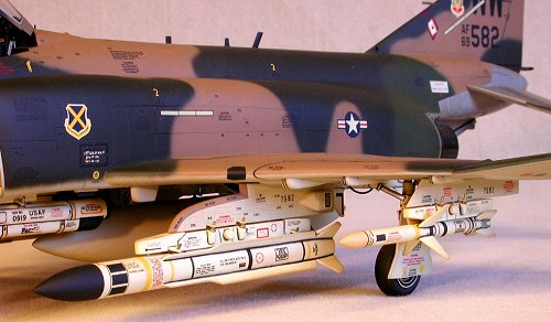
At this point, I returned to the wing to finalize the ordnance fit. I substituted all kit-supplied items in favor of the equivalent (though much more accurately molded) pieces from Hasegawa’s various aircraft weapon sets. All were attached via the brass peg method described earlier. Additional details were added to the missiles and pylon adapters. I used various bits of steel, brass and aluminum tubing to build miniature rocket motors, while strips of suitably shaped aluminum sheet were fashioned, into sway braces. Short sections of straight pins with the heads filed flat replicated the casing nuts.
The ALQ-119 (V) ECM pod at station 3 was drilled to accept pegs made from short lengths of paper clip. I drilled two holes through the adapter at the appropriate locations to allow it to slide easily into position on top of the pod. After drilling two corresponding holes into the #3 missile well, I bent the pod/adapter’s pegs slightly divergent to permit a snug, but removable friction fit. The remaining Sparrow missiles were installed in similar fashion at stations 4, 6, and 7.
I plugged in all missiles, pylons, the fuel tank, and ECM pod and test-flew the airframe around in my studio. +9Gs and –5.5Gs (well beyond the design limits of the real Phantom II!) were achieved without incident, doubtlessly disappointing the "Gotcha" gremlins, which inhabit all modelers’ workshops. I had, however, taken the precaution of spreading a thick, down-filled comforter on the floor.
By now, many will be scratching their heads and asking, "What’s with this jerk? Is he trying to make Alcoa Aluminum and Bethlehem Steel rich or is he a masochist?". Well mateys, it’s simple. All modelers who are in the military generally dread the call from personnel notifying them of a PCS move (a transfer to a new duty station for those of you not in the loop). Faced with the unerring certainty of movers, earning the minimum wage, packing and transporting all their worldly possessions (including museum-grade build-ups) the modeler’s dilemma is simple—give the models away, throw the models away, or pack them yourself and pray.
 A sturdily constructed, well-packed model can survive even
modestly rough handling with minimal ill effect. I spend more time building a
solidly made mil-spec model so I spend less time repairing it. As a bonus, I
have never had to make emergency repairs at a contest or show while the unwashed
ambled about, pooh-poohing shoddy assembly techniques.
A sturdily constructed, well-packed model can survive even
modestly rough handling with minimal ill effect. I spend more time building a
solidly made mil-spec model so I spend less time repairing it. As a bonus, I
have never had to make emergency repairs at a contest or show while the unwashed
ambled about, pooh-poohing shoddy assembly techniques.
Returning to the model, I removed all the landing gear components from the sprues and cleaned them up. There were some ejector pin marks on the main struts, which required filling and sanding. Along the way I cut off the tie-down rings and replaced them with the separately molded Testor’s/Italieri parts. A word of caution: The main gear strut, with the door installed, should be positioned in such a way that the bottom edge of the door is parallel to the ground. The Hasegawa struts must be installed with a slight amount of forward angle to accomplish this. Be sure to test-fit the wheel/strut/door combo before permanent attachment. I used Testor’s liquid cement to tack the struts in place while I fiddled with the angle. When I was satisfied, I hard glued them in place with CA.
Detail Associates’ model car ignition wire was added to the retraction jacks to simulate hydraulic lines. The nose strut’s hydraulic cylinder was poorly defined so I removed and replaced it with a scratch-built one made from sprue. Ignition wire was used for its hoses. The landing/taxi light assembly was detailed with bits and pieces, while MV lenses replicated the bulbs. I flattened the tires slightly with a file and sandpaper, test-fitted them to the struts, then removed them to facilitate painting.
At this point, I examined all the various blade antennas that had yet to be installed. All appeared slightly underscale and/or poorly defined. I fabricated new ones from Evergreen sheet and installed them into rectangular slots cut into the fuselage at the correct locations. A ventral hemispheric antenna forward of the nose landing gear was replicated with a dome-headed straight pin. After a final inspection for constructional flaws, it was off to the paint shop.
|
PAINT & DECALS |
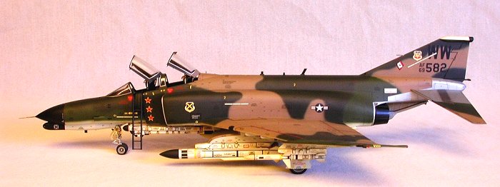
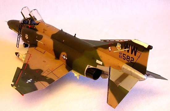
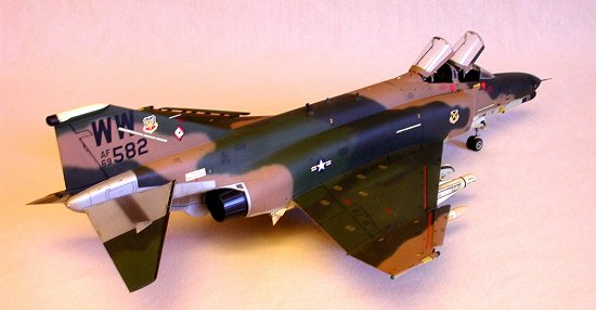
All wheels, struts, gearwells, and inner door surfaces were painted Testor’s gloss white (FS 17875). When dry I washed all recesses with Liquitex non-acrylic black watercolor, suitably thinned. I sealed the wash with a heavy coat of Testor’s Dullcote Lacquer. After masking the struts and wells, the exterior colors were sprayed on freehand using Hasegawa’s color plate as a guide. The Euro I scheme illustrated carries the same pattern as the SEA camouflage—only the colors are different. Testor’s paints from the Modelmaster line were used exclusively.
I began with the light gray underside (FS 36622). This was followed by the tan areas on the upper surfaces (FS 30219). This color has always appeared too dark to me on a model so I cut it 20% with flat white. Next, I painted the medium green (FS 34102).
Testor’s dark green (FS 34079) has almost the same specular intensity as their medium green. Most photos of actual aircraft show a marked differential between the greens, even in monochromatic (B&W) format. After examining the color chips in my FS595a outdoors in bright sunlight, I darkened the 34079 green with approximately 10% flat black. This produced a satisfactory amount of contrast.
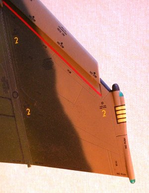
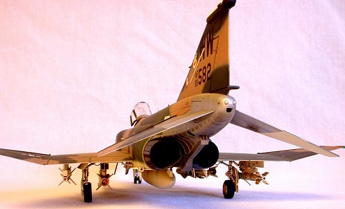
 The bare metal areas of the stabilators and aft fuselage were
painted with buffing-type Spray ‘n’ Plate (now in the Testor’s line).
Powdered graphite was used to tint various panels of the stabs as well as
provide some exhaust staining around the afterburner cans and arresting hook.
The tailpipes themselves were sprayed flat black. Graphite was dusted on the
inside with a wide sable-hair brush to create a grungy look, while the exteriors
were burnished to a modest sheen with the graphite applied by Q-tip. I finished
by buffing the exteriors lightly with (don’t laugh, buckos) a cotton diaper.
The bare metal areas of the stabilators and aft fuselage were
painted with buffing-type Spray ‘n’ Plate (now in the Testor’s line).
Powdered graphite was used to tint various panels of the stabs as well as
provide some exhaust staining around the afterburner cans and arresting hook.
The tailpipes themselves were sprayed flat black. Graphite was dusted on the
inside with a wide sable-hair brush to create a grungy look, while the exteriors
were burnished to a modest sheen with the graphite applied by Q-tip. I finished
by buffing the exteriors lightly with (don’t laugh, buckos) a cotton diaper.
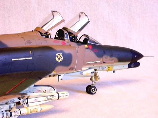
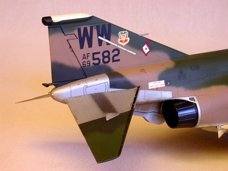
The canopy frames were undercoated with black, then neutral gray (FS 36270), followed by the appropriate exterior color. The fin tip fairing was masked and sprayed insignia white. When dry, the rear of the fairing was masked and sprayed black along with the radome and chin fairing.
At this point, I painted the tires and installed them so the model could sit and dry without props or supports, which might mar the paint. I gave the model several coats of decal primer (Testor’s Glosscote Lacquer) to level the colors in preparation for decaling.
While the Glosscote dried, I painted the remaining parts in the appropriate colors. An added benefit of installing brass pegs on all the ordnance was having a convenient (and concealed) spot for holding the items with a pair of Kelly clamps (hemostats) while painting them. Having decided on a scheme, it was time for decals.
I have a couple of rules when it comes to decals:
1.) I never use kit decals unless I have to, and
2.) I never have to
This is not to say I’m on a jihad against kit decals. Some of the Scalemaster and Propagteam sheets provided in many kits look pretty good. However, a lot of the OEM decals furnished with stock kits, quite plainly, suck. They’re thick, or they’re printed off-register, or they’re incorrectly colored, or they don’t adhere, or they…well you get the idea (are you listening, Monogram? Hasegawa? Tamiya?) More importantly, I don’t want to visit another modeler and find the same model I built sitting in his or her display case.
After finding several photos in different references, I decided on 69-7582, a Wild Weasel assigned to the 563rd TFS, 37th TFW and based at George AFB, near Victorville, California in the mid 1980’s. Microscale, in a rare moment of lucidity, issued several sheets some years back, which were solely dedicated to squadron, wing, and major air command insignia of the Air Force. In an even rarer moment of lucidity, I squirreled away several of these sheets. I found the necessary squadron and wing badges here. The remaining decals are also Microscale (or Superscale) from various F-4 sheets with the notable exception of the low-level tape lights, which are Scalemaster. The MiG kills depicted on the portside intake ramp are enigmatic. I researched every F-4E MiG kill claimed during the Vietnam War through multiple references and found no corroboration. I am dubious that 69-7582 ever served in SouthEast Asia during hostilities. However, the red stars appear in several photos from different sources. Perhaps they belong to the squadron or wing.
 I followed the Microscale system religiously while decaling.
Micro-Set and -Sol sufficed for most items, with Solvaset held in reserve for
the more aggravating pieces. Colored bands were cut from solid decal film to
stripe the ECM pod and missiles (yellow for live warhead, brown for live rocket
motor). A 1/72 German armor sheet provided small-font numbers to serialize the
pylons to the aircraft, while a Scalemaster accessory sheet was used to stencil
the missiles.
I followed the Microscale system religiously while decaling.
Micro-Set and -Sol sufficed for most items, with Solvaset held in reserve for
the more aggravating pieces. Colored bands were cut from solid decal film to
stripe the ECM pod and missiles (yellow for live warhead, brown for live rocket
motor). A 1/72 German armor sheet provided small-font numbers to serialize the
pylons to the aircraft, while a Scalemaster accessory sheet was used to stencil
the missiles.
When I was satisfied with the overall effect, I sprayed on several heavy coats of Testor’s Dullcote Lacquer after masking the bare metal areas with 3M Post-It note paper. When dry, I used the Liquitex watercolor again to highlight the moveable control surfaces and any other recessed details. A light misting of Dullcote sealed this wash. Thin strips of silver decal were used to simulate the window seal on the canopies and windscreen. I attached the landing gear doors and landing/taxi light assembly with Testor’s liquid cement.
To prevent hours of modeling pleasure, I painted the face curtain grab handles on part D7 (x2) yellow, then used thin strips of black decal for striping. These were then attached to the seats with Microscale Liquitape. After plugging all the ordnance into the proper underwing locations, I flipped the model rightside up and installed the canopies and pitot tube with white glue.
|
CONCLUSIONS |
Hasegawa’s F-4G, while not an exceptional kit, assembles into a more-than-passable replica of a Wild Weasel, even when built SOB (Straight Out of the Box) by a three-level (Air Force-speak for a ‘gomer’, Marine-speak for a…never mind). Detailing is adequate, fit is acceptable, and vices (with the problematical exceptions of the intakes and stabilators) are few. The assembled model scales out well when compared to published specifications and dimensions. Intermediate and advanced modelers will doubtless avail themselves of the plethora of cottage-industry aftermarket upgrades and goodies, which were but a pipedream when I built this model in 1990. Perhaps the most significant criticism I can offer surrounds the poor quality of the decal sheet. If we could just get Mr. Aeromaster to talk to Mr. Hasegawa…
|
REFERENCES |
1. Koku-Fan: Famous Airplanes of the World, No. 118, F-4E/F/G Phantom II
2. Koku-Fan: Illustrated—F-4 Phantom II
3. Wild Weasel: The SAM Suppression Story – Larry Davis, Squadron/Signal Publications
4. Phantom II: A Pictorial History – Lou Drendel, Squadron/Signal Publications
5. USAF Phantoms: In Combat – Lou Drendel, Squadron/Signal Publications
6. F-4 Phantom II: In Action – Larry Davis, Squadron/Signal Publications
7. F-4 Phantom II: In Detail And Scale – Bert Kinzey, Kalmbach Publications
8. MiG Kill Markings From The Vietnam War – Bert Kinzey & Ray Leader, Kalmbach Publications
9. McDonnell-Douglas F-4E Phantom II: Aerofax Minigraph 20 – Tim McGovern
10. F-4 Phantom: Warbirds Illustrated No. 27 – Robert C. Stern, Osprey Publishing
11. USAF Phantoms: Tactics, Training and Weapons – Anthony M. Thornborough
12. T.O. 1F-4E –1: USAF Technical Order – Government Printing Office, 1979
On a personal note I would like to extend my gratitude to Frank Macsorley and Craig Baumer, NCOs with the District of Columbia and Maryland Air National Guards (respectively) whose assistance in helping me sort through the various systems of the actual aircraft made this project possible.
ã
2000 Roger M. JacksonDecember 2000
If you would like your product reviewed fairly and quickly by a site that has over 1,700 visits a day, please contact me or see other details in the Note to Contributors.