Airmodel 1/72 Fokker-VFW 614
| KIT #: | 0 |
| PRICE: | €28 for kit and resin set |
| DECALS: | None provided |
| REVIEWER: | Carmel J. Attard |
| NOTES: | Vacuform with resin parts |
| HISTORY |
 One of
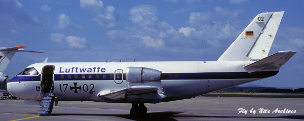
the jet transport aircraft that saw service with the Luftwaffe between the years
1976 and 1999 mainly as a VIP and other transport duties was the Fokker VFW 614.
This aircraft was of a unique design because unlike other twin jet engine
aircraft the VFW614 had the engines mounted on pylons fitted over the main
planes at an area close to the wing roots. Originally it was planned to be a
short haul commercial transport.
One of
the jet transport aircraft that saw service with the Luftwaffe between the years
1976 and 1999 mainly as a VIP and other transport duties was the Fokker VFW 614.
This aircraft was of a unique design because unlike other twin jet engine
aircraft the VFW614 had the engines mounted on pylons fitted over the main
planes at an area close to the wing roots. Originally it was planned to be a
short haul commercial transport.
The
VFW 614 programme was a collaborative production programme under the leadership
of VFW-Fokker; participants included the Dutch Fokker-VFW and Belgian SABCA and
Fairey concerns. The aircraft history goes back to July 1971 when first of the
three prototypes commenced the test programme. The first production aircraft
flew on April 28th 1975. This was delivered to Cimber Air in August
of the same year. Production of 30 authorized with orders for 16 aircraft. This
included two for Cimber Air, eight for
 Touraine Air Transport, three for Air
Alsace and three for the Federal German government. There was planning for a
stretched version with accommodation for up to 50 passengers and was proceeding
at the beginning of 1977 but this did not seem to have progressed beyond the
experimental consideration stage. The only few occasions that I was able to spot
a VFW 614 was way back in 1979 and in early 1980 when the type came to land at Luqa airfield in Malta as a VIP transport and in each case had on board a German
high ministerial delegation that had meetings with the local government. The
meetings were held at the prime minister office at the Oberge De Castille in
Valletta.
Touraine Air Transport, three for Air
Alsace and three for the Federal German government. There was planning for a
stretched version with accommodation for up to 50 passengers and was proceeding
at the beginning of 1977 but this did not seem to have progressed beyond the
experimental consideration stage. The only few occasions that I was able to spot
a VFW 614 was way back in 1979 and in early 1980 when the type came to land at Luqa airfield in Malta as a VIP transport and in each case had on board a German
high ministerial delegation that had meetings with the local government. The
meetings were held at the prime minister office at the Oberge De Castille in
Valletta.
The VFW 614 was powered by two 7,280 lb RR/Snecma M45H Mk 501 turbofans that gave it a maximum speed of 457 mph at 21,000ft and a maximum cruise of 449 mph at 25,000ft. It had a maximum take off weight of 44,000lbs. It carried a basic flight crew of 2 and standard layout for 40 passengers in rows of 4. The VFW 614 had a span of 70ft 6.5 in, length of 67ft 7in and a wing area of 688.89 sq ft.
| THE KIT |
Airmodel of Germany is the only kit producer to have the VFW614 in their range
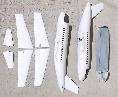
of kits to the popular scale of 1/72. The VFW 614 comes as a vacform kit in
white plastic. There are 44 parts blistered on two sheets all enclosed in a
polytene bag complete with a good instruction sheet. The kit parts include
fuselage halves, mainplanes, tailplanes, wheels engines, aileron guides, wheel
well doors. There is also a clear vacform cockpit canopy in acetate. Apparently
the Airmodel Products has started to issue the kit with resin parts as a few
days after I got the kit by post I also received a detail resin set to go with
the same model. These were in fact replacement parts for the kit smaller vacform
items, which are also contained in the original vacform kit, and they certainly
save a 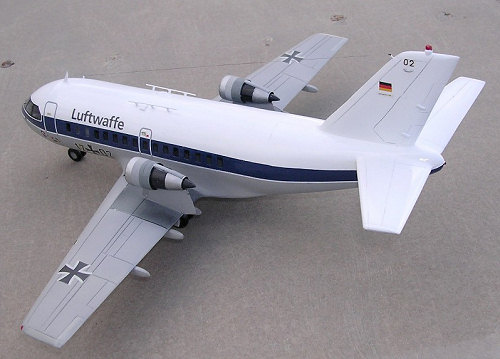 lot of time since much of the detail work comes on this set cast in
medium grey resin. These consist of a detailed instrument panel, cockpit floor
complete with nose wheel well, radio compartment, crew seats, control columns,
cockpit bulkhead, parts to produce the two turbofan engines complete with the
first stage rotor blades, six trailing edge spoilers, and a complete set of
wheels, six in number and rudder pedals.
lot of time since much of the detail work comes on this set cast in
medium grey resin. These consist of a detailed instrument panel, cockpit floor
complete with nose wheel well, radio compartment, crew seats, control columns,
cockpit bulkhead, parts to produce the two turbofan engines complete with the
first stage rotor blades, six trailing edge spoilers, and a complete set of
wheels, six in number and rudder pedals.
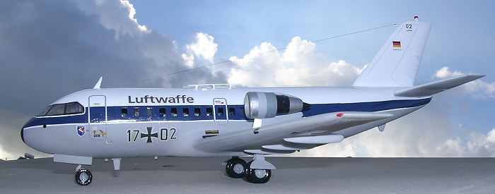
A spread A4 size instruction sheet contains a good scale plan of sufficient detail and accuracy to a scale of 1/72 and a side view depicted in Luftwaffe markings which is exactly the type of finish I always had in mind to build as it was in the same colours that I saw the type at Luqa airfield. The three machines that were in service with the Luftwaffe were carrying designations 17-01, 17-02, and 17-03. On the other side of the instruction sheet there is an exploded view of the kit parts. Also given are detail drawings of the bulkheads, which have to be made from the ample supply of backing plastic card contained with the kit parts. A plan drawing is also provided to enable you to cut the passenger floor area. Detail for sets of seats to passenger area are also given but I left these out as little could be seen through the cut side windows. A galley/toilet arrangement can also be added to the rear starboard side of the cabin but again little could be appreciated or visible through the 12 side windows on each side.
| CONSTRUCTION |
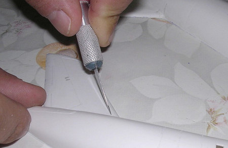
I have
started building the model using the standard method for vacform kits. i.e.:
marking the blistered parts outline with a dark felt pen, followed by cutting
with an exacto blade along the marking, then bend the part to and fro until it
detaches from the backing plastic. Each of the parts is sanded on medium coarse
sanding paper until the desired uniform edges are obtained. In the
 case of the
wing halves these needed scraping down the trailing edges as the vacform items
are often on the thick side. This also applies to the rudder area. The windows
were then drilled and shaped with a smooth file as per drawing given.
case of the
wing halves these needed scraping down the trailing edges as the vacform items
are often on the thick side. This also applies to the rudder area. The windows
were then drilled and shaped with a smooth file as per drawing given.
 The
fuselage sections were reinforced internally especially around the wing joining
area which tended to be of rather thin plastic section. This was made stronger
by adding on the inside a couple of laminated strips to make it thicker and
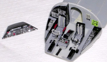
stronger. The resin cockpit office was then assembled with seats, rudder pedals, coaming, instruments, control columns and other interior detail. Cockpit was
painted medium grey with seat cushions in bright blue and straps cut from
masking tape to suite. A good source of reference to pick good photos of the
interior of the 614 will be to visit the web site
www.airliners.net.
The
fuselage sections were reinforced internally especially around the wing joining
area which tended to be of rather thin plastic section. This was made stronger
by adding on the inside a couple of laminated strips to make it thicker and
stronger. The resin cockpit office was then assembled with seats, rudder pedals, coaming, instruments, control columns and other interior detail. Cockpit was
painted medium grey with seat cushions in bright blue and straps cut from
masking tape to suite. A good source of reference to pick good photos of the
interior of the 614 will be to visit the web site
www.airliners.net.
The
assembled resin office was then inserted in front half of fuselage section. This
already had the area cut where the clear Perspex was to be fixed. After fixing
the layout with super glue, I then made a partition under the crew and passenger
deck that will encase the metal weight to avoid a tail sitter. Metal pieces were
wrapped in tissue paper then inserted inside. The tissue paper will prevent the
metal pieces from running loose in their encasement. The fitting of the resin
sub assembly was not as good as I have expected but left a small gap which could
be filled with segmented plastic bits around the circumference of the fuselage
inside area. To the rear of the cockpit bulkhead there is an open door through
which dark grey cockpit floor could be viewed. Cross channels and other detail
to main wheels and nose wheel wells compartment were added. These remain visible
through the open bays. Plastic tabs were fixed to the two sides of the fuselage
joining faces. These alternated with opposing ones. Two bulkheads cut from
plastic card were then added to rear of cabin. These added further
 strength to a
medium size fuselage. The main wheel wells that lie under the fuselage and
partly under the wing roots were then cut and shaped to conform to scale plans.
I then devised the exact location of the three undercarriage legs/oleo. Scratch
built oleos were then constructed from scrap plastic sprue of correct diameters.
At this stage the fuselage halves were fixed together, using Britfix cement and
after allowing these to set for 24 hours, I moved to the next step.
strength to a
medium size fuselage. The main wheel wells that lie under the fuselage and
partly under the wing roots were then cut and shaped to conform to scale plans.
I then devised the exact location of the three undercarriage legs/oleo. Scratch
built oleos were then constructed from scrap plastic sprue of correct diameters.
At this stage the fuselage halves were fixed together, using Britfix cement and
after allowing these to set for 24 hours, I moved to the next step.
It was now the turn for the wings to join the fuselage. I have predrilled two holes, 3/16 inches at the wing joining face area on the fuselage and inserted two long sprues. These were to act as wing spars as well as guide lugs for the wings. The wings, which at this stage were two complete sub assemblies, also had two holes drilled in line with those on fuselage root section. A jig was constructed out of thick cardboard using the front elevation drawing given on scale plans. This was to support the wings as they set to dry once fixed to the fuselage and also gave the wings the precise dihedral for the wings. This operation may have taken a good hour by itself but it was the turning point of the whole assembly sequence. Once more time was allowed to set (24 hours) and the fuselage with wings could be handed at liberty. Putty was added to wing roots on both sides. This was applied in layers intermittently in order to avoid sink or shrinkage from developing. After two days the putty was sanded down to desired blend at fuselage to wing roots. Tail planes were also fixed using dowels to ensure their correct fixing position and checking these from every angle. A slight amount of putty was needed at the joining faces.
The cockpit Perspex was of rather thick acetate and was not the type to cut with a pair of scissors. I used an exacto saw to cut along the mark where the part was to join the roof area. The width of the canopy was slightly wider than the fuselage space. So I bent it gently until the correct width conformed to that of the fuselage. This was first fixed with white glue, followed by tiny drop of super glue. Application of a small amount of putty blended the cockpit canopy with the fuselage to good effect.
 Before
setting to add the tiny aerials, antennae etc to the exterior of the aircraft,
all the surface details in form of panel lines were refreshed by scribing the
lines using the blunt back of a modeling knife. Surfaces were then smoothened
with wet and dry fine sanding. Small imperfections and blemishes at the rear of
the wing roots were attended to with a small amount of putty followed by further
smooth sanding. It was time to add detail to fuselage and wings. This consisted
of: Outer flap guide fairings, rudder trim tab drive, rudder servo tabs, VOR
aerials on tail fin, tail bumper, and repositioned passenger entrance lobby on
starboard side. The entrance door forward of fuselage on starboard side was
blanked. Also added VHF blade aerial, anti collision light on roof and at tail
fin tip, navigation light to under fuselage and landing light to leading edges.
Cabin roof fairings and horizontal antennae were also added as final items since
these could break easily. The model was checked for the correct sit on the
undercarriage before the final paintwork is commenced when no further minor
alterations were required.
Before
setting to add the tiny aerials, antennae etc to the exterior of the aircraft,
all the surface details in form of panel lines were refreshed by scribing the
lines using the blunt back of a modeling knife. Surfaces were then smoothened
with wet and dry fine sanding. Small imperfections and blemishes at the rear of
the wing roots were attended to with a small amount of putty followed by further
smooth sanding. It was time to add detail to fuselage and wings. This consisted
of: Outer flap guide fairings, rudder trim tab drive, rudder servo tabs, VOR
aerials on tail fin, tail bumper, and repositioned passenger entrance lobby on
starboard side. The entrance door forward of fuselage on starboard side was
blanked. Also added VHF blade aerial, anti collision light on roof and at tail
fin tip, navigation light to under fuselage and landing light to leading edges.
Cabin roof fairings and horizontal antennae were also added as final items since
these could break easily. The model was checked for the correct sit on the
undercarriage before the final paintwork is commenced when no further minor
alterations were required.
| COLORS & MARKINGS |
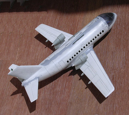
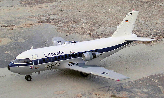
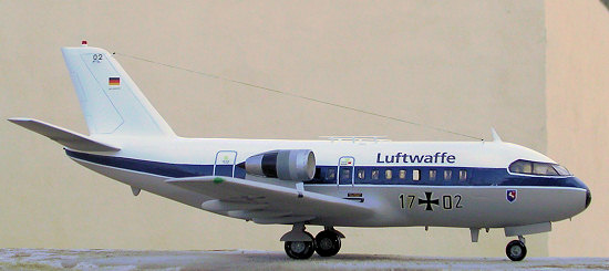 The
assembled kit was given an overall coat of semi matt white followed by light
aircraft grey to all the lower surfaces. The surfaces were once more checked for
imperfections and were given another coat of light aircraft grey. The grey lower
surfaces were masked and the upper surfaces were airbrushed in white. The white
was again masked and a blue trim was painted on. During the time allowed for the
paint to dry, I went to the decal box where I forked out the appropriate size of
markings for the VFW 614. I am thankful to Gordon Zammit, another keen modeler,
who offered to scan and print the legend Luftwaffe that appears on the fuselage
sides to the dimensions I have given him. An HF long wire antenna was added which joined the
tip of tail fin to a point positioned on the forward roof area and offset to
starboard. The completed model was finally given an overall coat of semi gloss
varnish using Revell brand.
The
assembled kit was given an overall coat of semi matt white followed by light
aircraft grey to all the lower surfaces. The surfaces were once more checked for
imperfections and were given another coat of light aircraft grey. The grey lower
surfaces were masked and the upper surfaces were airbrushed in white. The white
was again masked and a blue trim was painted on. During the time allowed for the
paint to dry, I went to the decal box where I forked out the appropriate size of
markings for the VFW 614. I am thankful to Gordon Zammit, another keen modeler,
who offered to scan and print the legend Luftwaffe that appears on the fuselage
sides to the dimensions I have given him. An HF long wire antenna was added which joined the
tip of tail fin to a point positioned on the forward roof area and offset to
starboard. The completed model was finally given an overall coat of semi gloss
varnish using Revell brand.
| CONCLUSIONS |
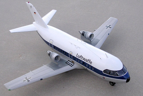
 This kit is highly recommended to those modelers
who are keen on post Luftwaffe aircraft as it builds into a pleasing model of a
moderate size. Experience with vacuum-form building will be an asset and thanks
to Airmodel who are now having a good set of resin parts available, custom made
for this model.
This kit is highly recommended to those modelers
who are keen on post Luftwaffe aircraft as it builds into a pleasing model of a
moderate size. Experience with vacuum-form building will be an asset and thanks
to Airmodel who are now having a good set of resin parts available, custom made
for this model.
December 2006
Copyright ModelingMadness.com. All rights reserved. No reproduction in any form without express permission from the editor.
If you would like your product reviewed fairly and fairly quickly, please contact the editor or see other details in the Note to Contributors.