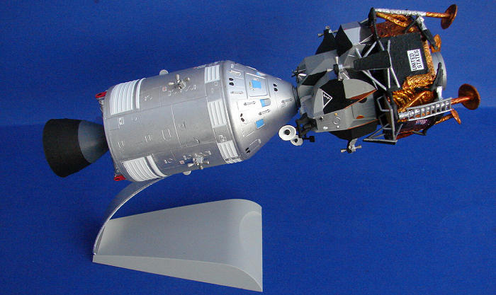
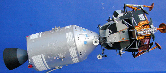
Dragon 1/72 Apollo 11 "Lunar Approach"
| KIT #: | 11001 |
| PRICE: | $44.00 MSRP |
| DECALS: | One option |
| REVIEWER: | Mark Hiott |
| NOTES: |
Contains both CSM and
LM. Complete decal sheet and p/e parts. |
| HISTORY |
"I believe
that this nation should commit itself to achieving the goal, before this decade
is out, of landing a man on the Moon and returning him safely to the Earth."
President John F. Kennedy, May 25, 1961.
 Apollo 11 was
the spacefilght which landed the first humans, Neil Armstrong and Edwin "Buzz"
Alrin, Jr on the Moon on July 20, 1969, at 20:17:39.
Apollo 11 was
the spacefilght which landed the first humans, Neil Armstrong and Edwin "Buzz"
Alrin, Jr on the Moon on July 20, 1969, at 20:17:39.
Launched from
the Kennedy Space Center on July 16, Apollo 11 was the fifth manned mission, and
the third lunar mission, of NASA's Apollo program. The crew consisted of
Armstrong as Commander and Aldrin as Lunar Module Pilot, with Command Module
Pilot Michael Collins. Armstrong and Aldrin became the first humans to walk on
the Moon on July 21. Their Lunar Module "Eagle" spent 21 hours 31 minutes on the
lunar surface, while Collins remained in orbit in the Command/Service Module
"Columbia". The three astronauts returned to Earth on July 24. They brought back
47.5 pounds (21.5 kg) of lunar rocks.
Five additional Apollo missions landed on the Moon between 1969 and 1972. Apollo 17, launched December 7, 1972, was the last Apollo mission to the Moon. Mission commander Eugene Cernan was the last person to leave the Moon's surface.
| THE KIT |
 Molded in gray plastic, the various sprues are sealed in separate bags. The part
count is quite high for the size of the model and detail looks good. The CM body
is molded as one part with a separate heat shield. The SM, however, is molded in
several parts which may make seams a problem. The LM decent stage has the
wrinkle of the foil covering molded on which makes for nice detail. One con, to
me, is the fact that the windows for the CM and LM are solid. Decals are
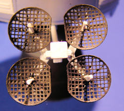
provided for the LM windows however. A small p/e fret contains the dishes for
the SM's High Gain Antenna.
Molded in gray plastic, the various sprues are sealed in separate bags. The part
count is quite high for the size of the model and detail looks good. The CM body
is molded as one part with a separate heat shield. The SM, however, is molded in
several parts which may make seams a problem. The LM decent stage has the
wrinkle of the foil covering molded on which makes for nice detail. One con, to
me, is the fact that the windows for the CM and LM are solid. Decals are
provided for the LM windows however. A small p/e fret contains the dishes for
the SM's High Gain Antenna.
This
kit appears to be exactly like the "Lunar Landing" kit with the exception of not
having the moon base and astronauts. It does, however, include the legs for the
LM in the open/landing configuration.
The
instructions are simple, being 8 steps. They are a bit unclear on a couple of
the steps and care must be taken to assure that the parts are assembled
correctly. A parts layout is also included, which will come in very handy later
in the build. Color callouts are for Gunze and MM paints. The painting and decal
layout is on the bottom of the box, which I'm not too fond of.
Decals are nicely printed and contain a
| CONSTRUCTION |
 First thing I want to touch on are the instructions. While they are more then
enough to build the kit, they contain several glaring errors. First off; the
sprue letters called out in the instructions don't match the letters stamped on
the sprues! Example: there are 2 separate B sprues called out in the
instructions, while 1 of them is stamped B, the other is stamped C. The 2 C
sprues are stamped D. While it's easy to identify the parts, it's something that
builders should be aware of. Second; in step 4, you assemble the high gain
antenna. Now, I don't know what parts Dragon was using, but they weren't in my
kit! While the numbers correspond to the parts, the parts look nothing like
what's shown in the instructions. Third; in step 6, the instructions don't show
the ladder on the front leg of the LM. Use part #C32 for the front leg. Fourth;
in step 7, the instructions don't mention part #B23. You have install this part
to the top of the decent stage or else you won't be able to mount the ascent
stage.
First thing I want to touch on are the instructions. While they are more then
enough to build the kit, they contain several glaring errors. First off; the
sprue letters called out in the instructions don't match the letters stamped on
the sprues! Example: there are 2 separate B sprues called out in the
instructions, while 1 of them is stamped B, the other is stamped C. The 2 C
sprues are stamped D. While it's easy to identify the parts, it's something that
builders should be aware of. Second; in step 4, you assemble the high gain
antenna. Now, I don't know what parts Dragon was using, but they weren't in my
kit! While the numbers correspond to the parts, the parts look nothing like
what's shown in the instructions. Third; in step 6, the instructions don't show
the ladder on the front leg of the LM. Use part #C32 for the front leg. Fourth;
in step 7, the instructions don't mention part #B23. You have install this part
to the top of the decent stage or else you won't be able to mount the ascent
stage.
I'm
gonna change the way I normally write a review and go through each step of the
build. There are several things which I can point out to make the build easier
for the next person.
Step
1: If you want to display the CSM and LM attached, use part #C4. If you want to
display the CSM by itself, install the docking probe parts. Part C12 is used in
both situations. A nose cone is also included to cover the probe if so desired.
Step
2: When assembling the SM, start with part #E2, it contains the locating tabs
for parts E4 and E8. You can then assemble the remaining panels. Part E5 is
located on the side of the SM just above the mount for the high gain antenna.
Test fit part C10 to help get it right. (A sharp observer will notice I got this
wrong) Mount the RCS bodies, parts D1 and D5, but leave the nozzles off until
after painting. If you want to use the kit stand, drill the hole out in part E6.
Careful assembly here will help close up the gaps.
Step
3: If you want to display the CSM and LM attached, turn over part C5 so the pin
faces upward and don't install parts B11. Leave off parts C8 and the SM engine
bell until after painting.
Step
4: Again, leave off the high gain antenna until later, it will just be in the
way while painting. Pay close attention mounting the CM to the SM. Part C2 is
located at the +z point of the CM, opposite the main hatch. Note the 3 small
panels shown in the instructions. The fit of part C10 is poor and care should be
taken when attaching it.
 Step
5: Assemble all the parts for the ascent stage, but leave off all the antennas,
radars and RCS nozzles. The fit of
the panels is poor and some trimming will help close the gaps.
Step
5: Assemble all the parts for the ascent stage, but leave off all the antennas,
radars and RCS nozzles. The fit of
the panels is poor and some trimming will help close the gaps.
Step
6: Attach the top of the decent stage, part A6, to the bottom, part F, before
attaching the legs. Again, fit is poor and there will be gaps that will need to
be taken care of. Leave off all the other parts until after painting.
Step
7: Although not mentioned in the instructions, part B23 will be needed to mount
the ascent stage to the decent stage. A good bond will be required here as the
attachment area is quite small.
Step 8: One part is not shown in the instructions, I don't know what the part number is as it was laying loose in the bag with the stand. It goes between the stand and the CSM body. I recommend making a new mount anyway as the one in the kit will never hold the weight of the completed kit. I drilled out the mounting and installed a screw instead.
| COLORS & MARKINGS |
The
Apollo LM has a very distinct color. I recommend anyone building this get copies
of Mike Mackowski's Space in Miniature #6 (the CSM) and #7 (the LM). In my
opinion, they are the best source of info. The layout on the back of the box is
pretty close and can be used as well.
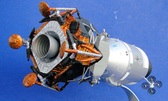
In
order to get the deep gold color of the descent stage, I used a trick from
another space modeler... I painted the decent stage MM chrome silver first and
then painted the appropriate areas with Tamiya clear yellow. It gives a nice
reflective look to the clear paint. After that was dry, I painted the black
areas with MM flat black. The upper sections of the legs were left in chrome
silver. The bottom of the decent stage was pa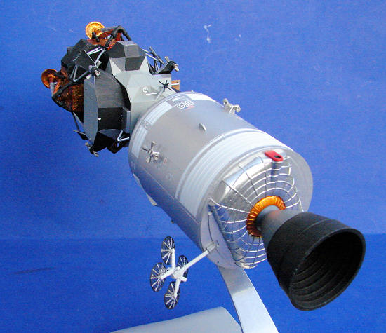 inted chrome silver and the engine
bell was painted MM aluminum outside and MM steel inside.
inted chrome silver and the engine
bell was painted MM aluminum outside and MM steel inside.
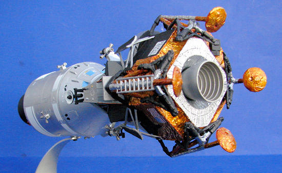
The
LM ascent stage is difficult to paint. There has been much debate in the various
space modeling groups as to what the actual color of the ascent stage is. I can
assure you, however, it is not to silver called for in the instructions. It has
been described as a "beigey gray" color. I have been told that Humbrol 40 is a
close match, but I was unable to find any in my LHS. So I opted to used what I
thought was close... MM Light Sea Gray. It's still a bit too "gray", but it's
close. After the gray was dry, various panels were painted flat black, chrome
silver or gold as required. The antennas were painted black with aluminum
mountings. The inside of the radars were painted flat white. The RCS deflectors
mounts were painted aluminum, as well as the backs. The fronts were painted flat
black. The porch was painted wood with silver rails.
The
CSM was first painted overall with MM flat white. The areas of the radiators was
then masked off and MM German Metallic Silver sprayed on. The windows were brush
painted with Testors Light Blue in the small bottle. The high gain antenna
mounts were painted MM flat white with flat black dishes. The framework on the
back of the dishes was painted chrome silver. The lower mount where it attaches
to the CSM was painted silver. The 2 vents on the lower panel of the CSM were
painted red with flat black openings. The SM engine bell was painted MM Gunship
gray on the upper section and flat black on the lower section and inside. The
lower section really should be a bit more metallic. The various RCS nozzles on
both the CSM and LM were painted with MM Steel.
At this point the decals were applied. There are only 5 for the LM, 2 on the decent stage and 3 windows on the ascent stage. The CSM on the other hand has a LOT of decals! Some of them are so small that they are really hard to see. Apply the decals before you install the RCS nozzles. The decals went down with no trouble and look good.
| FINAL CONSTRUCTION |
 After painting go back through the inst
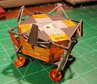 ructions and install the parts left off.
On the CSM, attach the lower vents, engine bell and RCS nozzles. At this point
you can also assemble, and attach, the high gain antenna. Attach the p/e dishes
with some thin CA glue. Care should be taken here as you need to get all 4
dishes aligned with each other as well as the mount.
ructions and install the parts left off.
On the CSM, attach the lower vents, engine bell and RCS nozzles. At this point
you can also assemble, and attach, the high gain antenna. Attach the p/e dishes
with some thin CA glue. Care should be taken here as you need to get all 4
dishes aligned with each other as well as the mount.
On
the LM, assemble the legs. The ladder on the front leg of the LM is not shown in
the instructions, but it is part #C32. Install the S-band, rendezvous radars as
well as the docking target. If you want to the rendezvous radar fixed, you can
use part B17, otherwise use the parts called for in the instructions. For the
front porch, use part #B12, not B19 as called for in the instructions. The last
parts installed were the RCS nozzles.
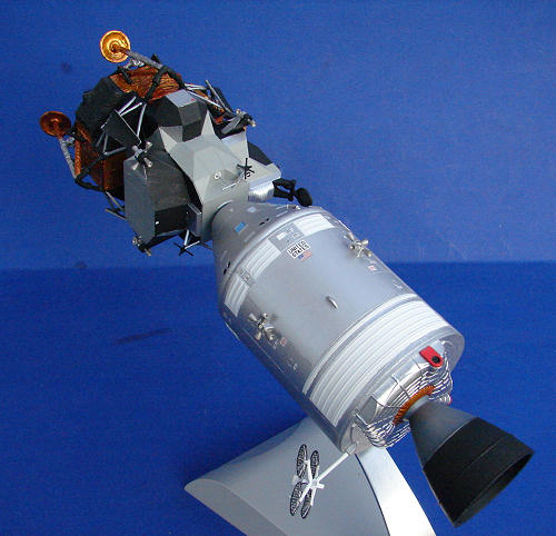
To
attach the LM to the CSM, line up the docking target with second window from the
left. I didn't use any glue here as the fit is quite tight.
| CONCLUSIONS |
There are a few inaccuracies in the kit. The most obvious being that the LM
decent stage is too small. The various radars are also not quite right. Also,
there are no folded landing probes provided for the LM footpads. However, it
builds into a very nice Apollo 11 and anyone who like real space models will
find it an enjoyable build. I can't recommend it to novices, due to the painting
and small parts, but anyone with a bit of experience should have no trouble.
| REFERENCES |
Wikipedia for the history
Space in Miniature
November 2011
Thanks to www.dragonmodelsusa.com for the preview kit. You can get yours at your local shop or have them order it for you.