
RVHP 1/48 HU-16E Albatross
| KIT #: | ? |
| PRICE: | $199.00 SRP |
| DECALS: | Three USCG options |
| REVIEWER: | Pat Earing |
| NOTES: |
Resin kit.
Conversion
decals from CanMil decals |
| HISTORY |
The Grumman HU-16
Albatross is a large twin-radial engine amphibious flying boat.
Originally designated
SA-16, it was
renamed HU-16 in 1962.
The Albatross
was designed to be able to land at sea in open ocean situations in order to
affect the rescue of downed pilots. Its deep-V cross-section and substantial
length helped make it possible for it to land in wavy conditions.
The majority of Albatrosses were used by the U.S. Air Force, primarily by the
Air Rescue Service, and initially designated them as
 SA-16. The
USAF utilized the SA-16 extensively in
SA-16. The
USAF utilized the SA-16 extensively in
The U.S. Navy also employed the HU-16D Albatross as a Search and Rescue
aircraft from coastal naval air stations, both stateside and overseas. It was
also employed as an operational support aircraft worldwide.
The HU-16 was also operated by the U.S. Coast Guard as both a coastal and
long-range open ocean SAR aircraft for many years until it was supplanted by the
HU-25 Guardian and HC-130 Hercules.
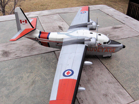
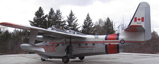
In the RCAF, the Grumman Albatross was selected to replace the World War II "Canso" amphibian employed on post-war Search and Rescue duties. Canada procured ten CSR-110s similar to the USAF's SA-16B but powered by 1,525 hp (1,137 kW) Canadian Wright-built R-1820-82 nine-cylinder, single-row, air-cooled, radial engines; these aircraft also had a triphibian landing gear. All ten rescue aircraft were delivered in 1960-61. The last aircraft was surveyed in 1971.
| THE KIT |
Imagine my
surprise when I stumbled upon a preorder list for an all resin RVHP HU-16 in
1/48 scale!
Is this real?
Although pricey, I preordered on the spot.
It took most of a year, but eventually a box full of beautiful light
tan resin showed up at my door, and my wait for a 1/48 scale Albatross was over.
So what does one
get from RVHP?
Upon opening the box I was struck by the absolute quality of the
casting. All
of the resin parts are bagged, many individually helping with both parts
recognition and shipping damage.
The fuselage comes in two large pieces, and looks every bit like an
injection molded model would with petite panel lines, amazing cast details and
thin-not at all like the resin kits I have built in the past.
The wings came in five parts with the outer sections being solid cast.
The tail surfaces were equally well cast, with no visible surface
bubbles and minimal warpage.
Two cowlings and engines are provided; although, the engine detail is
weak and not up to the same standards as the rest of the kit.
In contrast, the propellers are exquisite, with
 fragile
detail throughout.
fragile
detail throughout.
The kit includes
a full cockpit; however, everything back of the cockpit bulkhead is left to the
builder to create.
The delicate resin cockpit parts are well thought out with easy to
remove casting blocks and minimal shipping damage present.
Although an overhead console is provided, the very visible controls
that hang down are not.
Additionally, no seatbelts are provided.
The instrument panel is a three part resin affair that has to be seen
to be appreciated; being wafer thin and cast with amazing detail.
Another
highlight of the kit is the simply stunning vacuformed canopy.
I have never seen anything like this clarity and strength in a
vacuformed canopy.
Simply state of the art!
RVHP thoughtfully includes two large and very clear canopies with the
kit and additional vacuformed window blisters being included on the sheet.
Fuselage side windows are also included, but as clear resin castings. If you go
to the trouble of scratch building the aft interior, you will want to look for a
more see through alternative.
 The landing
gear is provided by detailed white metal castings.
These are large and very soft.
The main wheels are well cast but look nothing like anything the Coast
Guard or Navy used on the HU-16.
The nose wheels, although simple, look the part and are adequate.
The landing
gear is provided by detailed white metal castings.
These are large and very soft.
The main wheels are well cast but look nothing like anything the Coast
Guard or Navy used on the HU-16.
The nose wheels, although simple, look the part and are adequate.
Missing from the kit are the many lumps and bumps, antennae, and tie down
details that all Albatrosses show.
The kit includes
sparse, but adequate instructions/construction outlines and a full view decal
placement guide.
The decals come sealed in a plastic bag on a large sheet and look the part.
My kit included decals for the USCG version which included the blue
fuselage stripe and a few of the necessary warning decals.
Although not an exhaustive sheet, the decals provided by RVHP are
adequate.
Additionally, I ordered a separate conversion direct from
| CONSTRUCTION |
 I began
construction by carefully removing the resin flash from all of the fuselage
window openings with a sharp #11 blade.
I also looked carefully at the fuselage halves for warpage.
RVHP has done an amazing job here, and for as thin and large as the
castings are, there was very little in the way of mismatch.
I did, however, take the two halves out to my wood shop and lightly
sand them on my large belt sander with 320 grit paper to get them perfectly
flat-not something for the weak of heart to try!
I began
construction by carefully removing the resin flash from all of the fuselage
window openings with a sharp #11 blade.
I also looked carefully at the fuselage halves for warpage.
RVHP has done an amazing job here, and for as thin and large as the
castings are, there was very little in the way of mismatch.
I did, however, take the two halves out to my wood shop and lightly
sand them on my large belt sander with 320 grit paper to get them perfectly
flat-not something for the weak of heart to try!
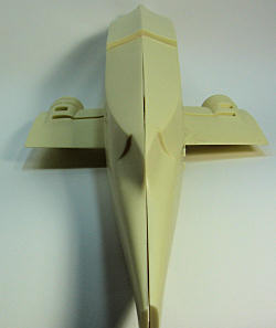
Satisfied that
my fuselage would go together without fuss, I separated the main well bay
inserts from their casting blocks and began to fit them to the fuselage
openings. The
detail of these parts is simply stunning, and very fragile.
Unfortunately, these parts are short in length by at least a
millimeter and did not completely fill the fuselage opening.
Looking over the parts breakdown for the gear doors, and numerous
images of the real aircraft I decided that this was not as big a fubar as it
looked. By
fitting the bays up to the top of the opening and leaving the rather large gap
at the bottom I saved myself considerable headache as the lower gear doors
ultimately covered the entire resulting gap.
Next I thought
about starting work on the cockpit.
For about 3 microseconds I considered a full interior with the aft
doors opened; however, I wanted to get the model built, and I had a bit of a
deadline so I quickly put that idea away!
It is about this time that I began to hear rumblings through the
Web-vine about problems with the wings on the long span version.
Well, forget about the cockpit, I decided I better find out if the kit
was going to be buildable because of the flawed wings.
I taped parts together and mated everything up as best I could looking
for something fatal.
Ultimately, I decided that all was fine and overall looked a whole lot
better than the last big resin kit I had built (a CollectAir Savage).
Just to be safe, and not feeling motivated to start on the cockpit I
took to assembling the wings.
I looked through my ‘stuff’ drawer for a large
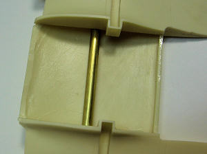 brass or
aluminum tube of sufficient length to support the wings.
I found a 3/8 diameter brass tube that just missed all the cast shapes
and details in the center wing section.
I did have to carve out areas of resin for the tube to pass all the
way through, but once done I was able to attached the two lower engine nacelle
sections to the center fuselage/wing top section leaving about 4 inches of
tubing protruding on both sides of the center section for the wings to attach
too.
brass or
aluminum tube of sufficient length to support the wings.
I found a 3/8 diameter brass tube that just missed all the cast shapes
and details in the center wing section.
I did have to carve out areas of resin for the tube to pass all the
way through, but once done I was able to attached the two lower engine nacelle
sections to the center fuselage/wing top section leaving about 4 inches of
tubing protruding on both sides of the center section for the wings to attach
too.
At this point I
took a deep breath and dug out a big drill.
I had yet to permanently attach the tube into the center section,
allowing me to remove it or slide it from side to side.
I marked a small line top and bottom where the center of tube came
through the center wing section with a pen, and placing the outer wing panels up
to the center section, marked a matching mark top and bottom on these.
Next I checked that the tube was centered in the airfoil section, and
once satisfied marked the center of the outer wing panels for drilling.
Using a 3/8 drill bit in my trusty Makita cordless drill, I began to
put a 4 inch deep hole in those large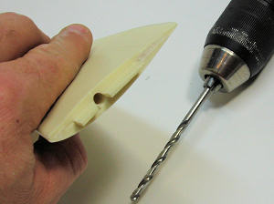 resin wings.
The key here is to make sure that you are not drilling on a slope, so I checked
and recheck my orientation as I drilled.
I thought about using my drill press, but the set up would have been
taxing with the odd tapering shape of the wings, so I freehanded the holes.
This process of drilling into the wing was nerve-wracking, as there is
not much free board and I wasn’t sure that I would get deep enough before I
poked the bit through the top or bottom of the wing…
I went slowly, and in the end all was well; although I could see the
hole near the end as a darkening in the resin, so I did come close!
resin wings.
The key here is to make sure that you are not drilling on a slope, so I checked
and recheck my orientation as I drilled.
I thought about using my drill press, but the set up would have been
taxing with the odd tapering shape of the wings, so I freehanded the holes.
This process of drilling into the wing was nerve-wracking, as there is
not much free board and I wasn’t sure that I would get deep enough before I
poked the bit through the top or bottom of the wing…
I went slowly, and in the end all was well; although I could see the
hole near the end as a darkening in the resin, so I did come close!
Sliding the
wings on, I could see that my initial assessment about the parts fit may have
been optimistic as there was a large step top and bottom; of at least 2
millimeters, and severe gaps as well.
About this time I entered into an online discussion with Tom Cleaver
and discovered that RVHP had realized their mistake and offered replacement wing
sections for those early kits.
Huh, how did I miss that?
Oh well, I was already committed.
I fiddled with the fit, bending and checking the wing with the
fuselage and a straight edge until I was okay with the shape and all the gaps
were was as close as I
 could get.
I then committed the wings and tubing to the center section with epoxy
and CA glue.
At this point I dug out my trusty can of bondo and some 60 grit sand paper and
went to work on that enormous expanse of resin.
Having grown up in a body-shop and spent years as a painter it felt
like a homecoming to sling mud and sand with such heavy grit paper.
I used a two part ‘bondo’ topcoat system produced by Evercoat that I
used in the bodyshop as a topcoat over bondo to ease feathering and fill the
large grit scratches before primer went on.
I initially sanded a large area of the wing with 60 grit-oh to see all
those panel lines disappear- and put on an initial coat of the ‘blue’, letting
it cure for a few minutes by the fire place.
I then sanded using a sanding block with 100 grit paper for a fast
cut.
Wiping the area down with lacquer thinner and blowing the dust away I reapplied
a second coat and feathered the whole mess out, again using 100 grit paper.
I should have finished up with 180 grit sandpaper, but I was trying to
make some time… but as I recall, cutting corners ALWAYS takes more time… Happy
with my body work I again cleaned everything with some lacquer thinner (don’t do
this with a plastic medium!) and mixed up some gray automotive lacquer primer.
This is a holdout for me as it is my primary primer system even with
plastic kits.
It builds thick and sands like a dream, with the added benefit that I have
been using it for thirty-five years and I know what I will get and how to apply
it. I sanded
my first coat with 180 grit paper, and because I used 100 grit earlier, had to
reapply a second heavy primer coat to fully fill all the scratches.
I finished all the sanding to 400 grit paper.
The wings looked fantastic, and I was confident that this build was
going to be okay.
I must add; at about this point in the wing construction, David at
could get.
I then committed the wings and tubing to the center section with epoxy
and CA glue.
At this point I dug out my trusty can of bondo and some 60 grit sand paper and
went to work on that enormous expanse of resin.
Having grown up in a body-shop and spent years as a painter it felt
like a homecoming to sling mud and sand with such heavy grit paper.
I used a two part ‘bondo’ topcoat system produced by Evercoat that I
used in the bodyshop as a topcoat over bondo to ease feathering and fill the
large grit scratches before primer went on.
I initially sanded a large area of the wing with 60 grit-oh to see all
those panel lines disappear- and put on an initial coat of the ‘blue’, letting
it cure for a few minutes by the fire place.
I then sanded using a sanding block with 100 grit paper for a fast
cut.
Wiping the area down with lacquer thinner and blowing the dust away I reapplied
a second coat and feathered the whole mess out, again using 100 grit paper.
I should have finished up with 180 grit sandpaper, but I was trying to
make some time… but as I recall, cutting corners ALWAYS takes more time… Happy
with my body work I again cleaned everything with some lacquer thinner (don’t do
this with a plastic medium!) and mixed up some gray automotive lacquer primer.
This is a holdout for me as it is my primary primer system even with
plastic kits.
It builds thick and sands like a dream, with the added benefit that I have
been using it for thirty-five years and I know what I will get and how to apply
it. I sanded
my first coat with 180 grit paper, and because I used 100 grit earlier, had to
reapply a second heavy primer coat to fully fill all the scratches.
I finished all the sanding to 400 grit paper.
The wings looked fantastic, and I was confident that this build was
going to be okay.
I must add; at about this point in the wing construction, David at
Having stalled
this long working on the wing there was nothing for it but to start on the
cockpit.
Using ModelMaster enamel I sprayed the entire interior section of the fuselage
with FS 16440 light gull gray.
I also sprayed all of the necessary small bits after I cleaned them of
flash. The
Instructions included by RVHP are of little or no use in placing parts, so I
resorted to a large number of on-line images and my two primary sources, the
Ginter and In Action HU-16 texts, to make sure that everything looked right for
both color and placement.
I used some leftover Eduard brass seatbelts and made some repairs to
the pilot and copilot seats
 using
evergreen styrene.
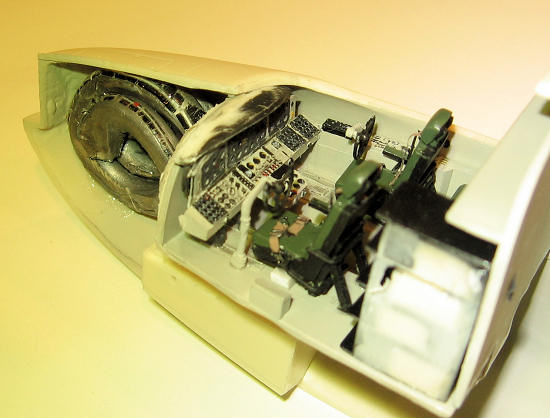
The radio rack is AMAZING, but very difficult to get away from the
molding blocks and unfortunately it is impossible to see on the finished model.
The instrument panel is a three part affair that sandwiches the
instrument dials/faces between a back and front instrument ‘panel’ with the
appropriate holes for the dials.
Overall this set up was a breeze to paint and very convincing-I would
like to see more of this style in our mainstream styrene releases. Finishing up
I painted and detailed the overhead console and added some Reheat brass levers
and bits of styrene for the controls that hang down here.
Placement of the cockpit is crucial, and although RVHP do give some
indicators for placement, it is at best a guess where to glue for final
placement. I
did find that the instrument panel bound with the coaming and required a fair
amount of sanding and fiddling before everything sat right and I could glue it
in place. At
this point I removed and fit a canopy so that I could confirm the for/aft
placement of the cockpit and the width of the fuselage before I glued it
together.
Additionally I added small strips of plastic to support the canopy at the resin
edge. If I
haven’t said it yet, these are the most amazing vacuformed canopies I have ever
worked with.
Thick, and consistent as well as crystal clear, these parts are simply amazing.
I masked and painted the inside of the canopy-don’t forget to check
references on the aircraft you intend to model as to whether you need to mask
the small round porthole windows aft of the main canopy glazing.
I then installed the overhead console.
using
evergreen styrene.
The radio rack is AMAZING, but very difficult to get away from the
molding blocks and unfortunately it is impossible to see on the finished model.
The instrument panel is a three part affair that sandwiches the
instrument dials/faces between a back and front instrument ‘panel’ with the
appropriate holes for the dials.
Overall this set up was a breeze to paint and very convincing-I would
like to see more of this style in our mainstream styrene releases. Finishing up
I painted and detailed the overhead console and added some Reheat brass levers
and bits of styrene for the controls that hang down here.
Placement of the cockpit is crucial, and although RVHP do give some
indicators for placement, it is at best a guess where to glue for final
placement. I
did find that the instrument panel bound with the coaming and required a fair
amount of sanding and fiddling before everything sat right and I could glue it
in place. At
this point I removed and fit a canopy so that I could confirm the for/aft
placement of the cockpit and the width of the fuselage before I glued it
together.
Additionally I added small strips of plastic to support the canopy at the resin
edge. If I
haven’t said it yet, these are the most amazing vacuformed canopies I have ever
worked with.
Thick, and consistent as well as crystal clear, these parts are simply amazing.
I masked and painted the inside of the canopy-don’t forget to check
references on the aircraft you intend to model as to whether you need to mask
the small round porthole windows aft of the main canopy glazing.
I then installed the overhead console.
Having checked
the canopy fit to the fuselage I was nearly ready to close everything up.
I tried using Future to help the clarity of the fuselage side windows,
but to my chagrin realized I had not washed them in the initial cleaning and the
Future would not stick to the windows because of the release agent.
After a good cleaning with lacquer thinner, all went well and they fit
like a dream with a little CA glue to hold them in place.
I also added the forward gear bay at this time.
Finally I taped the entire aircraft together
 and
attempted to figure out how much lead weight this tail sitter was going to need.
In the end all I can say is that I used an enormous amount of fishing
weight to get this one to stay on its wheels. Weight in, and a final check over
finished, I closed up the fuselage halves with CA glue and gave the seams a
light sanding as well as an initial coat of primer.
and
attempted to figure out how much lead weight this tail sitter was going to need.
In the end all I can say is that I used an enormous amount of fishing
weight to get this one to stay on its wheels. Weight in, and a final check over
finished, I closed up the fuselage halves with CA glue and gave the seams a
light sanding as well as an initial coat of primer.
Moving back to
the wings I began the process of rescribing all the lost detail.
Using an Olfa P cutter for the first time I was pleased with the speed
and accuracy I achieved with this sometimes tedious stage.
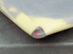
Images of HU-16s show a large and distinctive wingtip light.
I cut out the appropriate amount of resin and made a cover out of an
old clear tooth brush that I keep for just this purpose.
I drilled and painted the bulbs, glued the assemblies in place and
polished them up.
Eventually I masked them with yellow Tamiya tape to protect them from
the construction to come.
Additionally I drilled and placed small MV lenses (part number LS-8)
on the underside of the wing approximately one inch out board of the outrigger
(center to center).
For some added detail around the lights I added a small photo etched
ring that came from the leftover stash.
Finally, I measured, confirmed those measurements and made clear
indents for mounting both the outriggers and the auxiliary fuel tanks later on.
Finished with
the wing assembly I final sanded the fuselage and completed the necessary
rescribing.
At this point I started thinking about how I was going to mount the wing solidly
to the fuselage.
I decided that I did not trust either CA or epoxy to hold t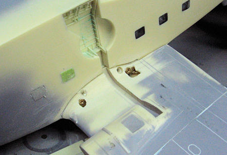 his
assembly together for the long term as the weight of the model was approaching
the absurd.
Going back to my wood shop I looked around
and came up with some brass #4 wood screws about 3/4 inch long.
I set the wing onto the fuselage and proceeded to drill holes through
the lower wing fairing area into the now concealed upper fuselage.
In order to counter sink the screws I drilled a slightly larger ‘dent’
for the screw head with a larger 3/8 drill bit for the screw head to rest in
after I had established the initial screw hole.
Towards the trailing edge I was forced to go through the outer layer
of resin to get a strong placement for the screw using the inner wing resin
surface; and although it looks bad, the holes were quite easy to fill and repair
with bondo.
Once I was satisfied that the screw heads were not going to stand
proud and would adequately hold the wing to the fuselage, I took the whole mess
apart and added 5 minute epoxy to the mix, screwed it all back together and
wiped off the excess. I
also installed the canopy at this time, and once all the glue was dry I sanded
and applied a small amount of bondo to the wing root and canopy top fuselage
area. These
areas took a multiple applications of primer and fussing to get correct, but
once finished and rescribed the model was starting to look the part of an
Albatross.
his
assembly together for the long term as the weight of the model was approaching
the absurd.
Going back to my wood shop I looked around
and came up with some brass #4 wood screws about 3/4 inch long.
I set the wing onto the fuselage and proceeded to drill holes through
the lower wing fairing area into the now concealed upper fuselage.
In order to counter sink the screws I drilled a slightly larger ‘dent’
for the screw head with a larger 3/8 drill bit for the screw head to rest in
after I had established the initial screw hole.
Towards the trailing edge I was forced to go through the outer layer
of resin to get a strong placement for the screw using the inner wing resin
surface; and although it looks bad, the holes were quite easy to fill and repair
with bondo.
Once I was satisfied that the screw heads were not going to stand
proud and would adequately hold the wing to the fuselage, I took the whole mess
apart and added 5 minute epoxy to the mix, screwed it all back together and
wiped off the excess. I
also installed the canopy at this time, and once all the glue was dry I sanded
and applied a small amount of bondo to the wing root and canopy top fuselage
area. These
areas took a multiple applications of primer and fussing to get correct, but
once finished and rescribed the model was starting to look the part of an
Albatross.
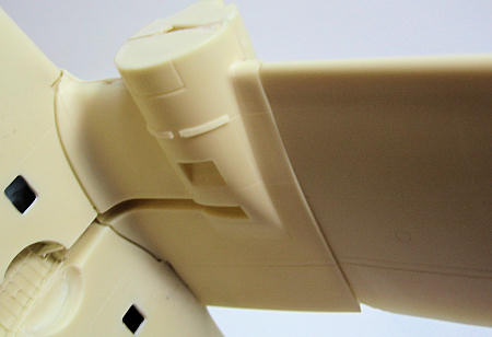
I next looked
into how best to attach the horizontal and vertical tail assemblies. RVHP
engineered these assemblies to the point that there were absolutely no gaps what
so ever; however, they sandwich on top of each other on a small fuselage ‘nub’
that did 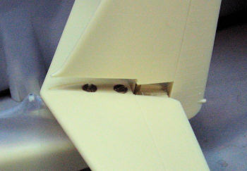 not
provide much gluing surface.
I again went for small brass screws and counter sunk them into the
center of horizontal tail assembly where the vertical tail mounts to hide them.
For the vertical surface I drilled holes into it and set short
sections of brass rod that I drilled corresponding mounting holes into the
center of the horizontal tail.
I made these joints permanent with epoxy and CA glue.
The horizontal tail was the only piece in the entire kit that showed
warpage. As
such I boiled the tail and worked the surface back straight using gloves to
protect my hands from the heat.
not
provide much gluing surface.
I again went for small brass screws and counter sunk them into the
center of horizontal tail assembly where the vertical tail mounts to hide them.
For the vertical surface I drilled holes into it and set short
sections of brass rod that I drilled corresponding mounting holes into the
center of the horizontal tail.
I made these joints permanent with epoxy and CA glue.
The horizontal tail was the only piece in the entire kit that showed
warpage. As
such I boiled the tail and worked the surface back straight using gloves to
protect my hands from the heat.
With all the
major assemblies together it was time to commit to which version of the
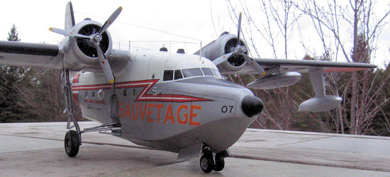
Albatross I was going to create-USCG or Canadian?
I had really already made up my mind, and choosing the Canadian
CSR-110, I started looking at the engines.
Unfortunately, the kit provided units are a real disappointment.
I had two Engines and Things Wright 1820’s in my stash, but the
CSR-110 used a different dash number which have subtle but obvious differences.
Eventually, through discussions on line, David at 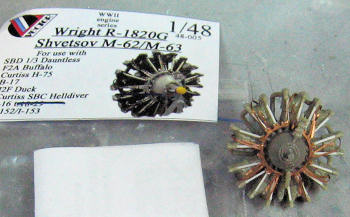 plastic
and created an exhaust ‘ring’ from round plastic tubing as well as a single
exhaust stack that were unique to the Canadian version.
The engines fit tight into the cowlings, and did require just a bit of
sanding on top of the cylinders to get them far enough in in to the cowlings to
look right. I
did push too hard on one engine, creating a lot of reassembly work as the engine
disassembled itself.
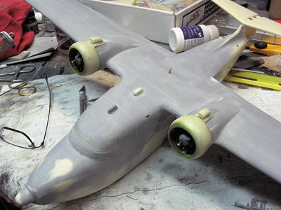
Once both engines were safely in the cowlings I drilled large (3/4
inch) holes into the front face of the wing cowling face so that the rear of the
engines could inset and allow the cowls to fit up flush with the wing cowling
sections.
Next I cleaned up the distinctive carburetor inlets and mounted them up top and
began priming and filling the cowling assemblies.
Unfortunately, as I looked at the kit and images of the real aircraft
it became apparent that the intakes were not far enough forward on the cowling
and of the wrong shape.
Nothing for it, I pried them off and used coarse grit sand paper to
reshape them, and when satisfied I reattached them about a quarter inch further
forward. Satisfied with the top, I began rescribing the wing root and cowlings.
Additionally, I added the small resin vent doors provided by RVHP to
the bottom of the cowling and masked up the engines with toilet paper.
plastic
and created an exhaust ‘ring’ from round plastic tubing as well as a single
exhaust stack that were unique to the Canadian version.
The engines fit tight into the cowlings, and did require just a bit of
sanding on top of the cylinders to get them far enough in in to the cowlings to
look right. I
did push too hard on one engine, creating a lot of reassembly work as the engine
disassembled itself.
Once both engines were safely in the cowlings I drilled large (3/4
inch) holes into the front face of the wing cowling face so that the rear of the
engines could inset and allow the cowls to fit up flush with the wing cowling
sections.
Next I cleaned up the distinctive carburetor inlets and mounted them up top and
began priming and filling the cowling assemblies.
Unfortunately, as I looked at the kit and images of the real aircraft
it became apparent that the intakes were not far enough forward on the cowling
and of the wrong shape.
Nothing for it, I pried them off and used coarse grit sand paper to
reshape them, and when satisfied I reattached them about a quarter inch further
forward. Satisfied with the top, I began rescribing the wing root and cowlings.
Additionally, I added the small resin vent doors provided by RVHP to
the bottom of the cowling and masked up the engines with toilet paper.
 Checking
over all the primer areas for flaws I began prepping the model for paint.
I used Tamiya yellow tape for all the window areas and mounted up the
metal nose gear.
The main gear required that I drill out the mount site as RVHP had cast it
considerably undersized.
Once the main gear was installed I began mounting up the gear doors,
detailing them with small bits of brass and plastic.
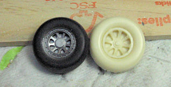
The main wheel are another serious let down of this kit.
Searching through images of Canadian CSR-110’s it became obvious that
they wore many different wheels throughout their careers, but for the late era
markings I was using they all tended to have an uncovered wheel with a hub
design very similar to those on the A-26.
Looking through my stash, I found an old set of Monogram A-26 wheels
and a resin set by True Details.
Not only were the A-26 wheels sporting the right look, they were the
correct diameter, if not a tad over wide.
Choosing the plastic wheels, I took them apart and reduced the width
by approximat
Checking
over all the primer areas for flaws I began prepping the model for paint.
I used Tamiya yellow tape for all the window areas and mounted up the
metal nose gear.
The main gear required that I drill out the mount site as RVHP had cast it
considerably undersized.
Once the main gear was installed I began mounting up the gear doors,
detailing them with small bits of brass and plastic.
The main wheel are another serious let down of this kit.
Searching through images of Canadian CSR-110’s it became obvious that
they wore many different wheels throughout their careers, but for the late era
markings I was using they all tended to have an uncovered wheel with a hub
design very similar to those on the A-26.
Looking through my stash, I found an old set of Monogram A-26 wheels
and a resin set by True Details.
Not only were the A-26 wheels sporting the right look, they were the
correct diameter, if not a tad over wide.
Choosing the plastic wheels, I took them apart and reduced the width
by approximat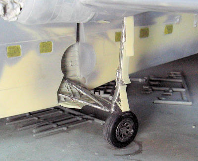 ely
1/8 inch and reassembled them.
Drilling out the mounting hole and putting the wheels onto the landing
gear leg revealed another problem with the lower main gear door sitting too low
on the leg and interfering with the tire.
Carefully prying it off of the leg I shortened the top, non-curved end
and shortened the mounting arm and reinstalled them.
It is about this time that I realized that my CA glue was NOT holding
on the white metal bits.
After considerable growling I found that if I roughed up all the
mating surfaces with 220 grit sandpaper that the glue would bite.
Nothing like doing a tricky assembly process three time each to try
your patience!
ely
1/8 inch and reassembled them.
Drilling out the mounting hole and putting the wheels onto the landing
gear leg revealed another problem with the lower main gear door sitting too low
on the leg and interfering with the tire.
Carefully prying it off of the leg I shortened the top, non-curved end
and shortened the mounting arm and reinstalled them.
It is about this time that I realized that my CA glue was NOT holding
on the white metal bits.
After considerable growling I found that if I roughed up all the
mating surfaces with 220 grit sandpaper that the glue would bite.
Nothing like doing a tricky assembly process three time each to try
your patience!
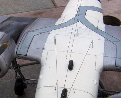
Finally ready
for paint I dug through my parts stash and located all of the funky antenna and
bumps that are all over the top of the Albatross.
Additionally, I drilled the large drain holes on the bottom near the
fuselage step, in the step, and inside the main wheel wells.
Against my better judgment I also drilled, pinned and added the
outriggers to each wing.
Time for paint!
| COLORS & MARKINGS |
 nose
radome, and antiglare panel and shot the whole plane with Floquil bright silver.
After a few days I masked the cheat line and sprayed the white areas
with Floquil reefer white.
I did have some pull up issues with the silver, so I touched those up
and sealed the whole thing in Testors gloss lacquer clear.
Again after a few days I masked everything real tight and sprayed MM
international orange that I had reduced 1 to 1 with Testers airbrush thinner.
Spraying with high pressure and light coats I applied color to the
wing tips and fuselage band; which I chose to paint rather than use the big
decals provided by CanMil.
Unfortunately, I had painted the ailerons with the international
orange, and they were supposed to be silver, so I wet sanded the mistake, masked
up the wings and also the tail, as I had forgotten to paint the rudder silver,
and repainted my omissions.
Finally, I masked up and painted the walkways on top of the cabin with
some dark gull grey MM enamel.
nose
radome, and antiglare panel and shot the whole plane with Floquil bright silver.
After a few days I masked the cheat line and sprayed the white areas
with Floquil reefer white.
I did have some pull up issues with the silver, so I touched those up
and sealed the whole thing in Testors gloss lacquer clear.
Again after a few days I masked everything real tight and sprayed MM
international orange that I had reduced 1 to 1 with Testers airbrush thinner.
Spraying with high pressure and light coats I applied color to the
wing tips and fuselage band; which I chose to paint rather than use the big
decals provided by CanMil.
Unfortunately, I had painted the ailerons with the international
orange, and they were supposed to be silver, so I wet sanded the mistake, masked
up the wings and also the tail, as I had forgotten to paint the rudder silver,
and repainted my omissions.
Finally, I masked up and painted the walkways on top of the cabin with
some dark gull grey MM enamel.
With the
painting finished I began the process of decaling.
The CSR-110 decals come from a company called CanMil and are new to
me. The sheet
looked great with everything in register and good color.
Starting on the bottom, I encountered no real problems over t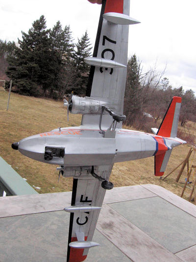 he
next few evenings as I applied the decals.
CanMil prints their decals onto a full carrier sheet, so careful and
close trimming are necessary, but they are sufficiently tough to withstand
moving and tugging for proper placement.
The decals also responded well to MicroSol setting solution, settling
nicely into surface detail.
I used some very fine black trim decal from Yellow Wings for the
walkway boarder color.
Finished with applying decals I let the model sit for a couple of days
to dry, and then sprayed a final sealer coat of semi-gloss Testors lacquer
clear.
Unfortunately, the CanMil decals, almost to a one, wrinkled and lifted from the
basecoat paint.
I don’t know if they just did not adhere well, or if I did something wrong,
but they sure did not like that top coat of clear.
I put everything on hold for a few weeks to let it thoroughly dry.
he
next few evenings as I applied the decals.
CanMil prints their decals onto a full carrier sheet, so careful and
close trimming are necessary, but they are sufficiently tough to withstand
moving and tugging for proper placement.
The decals also responded well to MicroSol setting solution, settling
nicely into surface detail.
I used some very fine black trim decal from Yellow Wings for the
walkway boarder color.
Finished with applying decals I let the model sit for a couple of days
to dry, and then sprayed a final sealer coat of semi-gloss Testors lacquer
clear.
Unfortunately, the CanMil decals, almost to a one, wrinkled and lifted from the
basecoat paint.
I don’t know if they just did not adhere well, or if I did something wrong,
but they sure did not like that top coat of clear.
I put everything on hold for a few weeks to let it thoroughly dry.
After a spell away, things did not look so bad… in some places. I gave the entire model a panel wash with black and burnt umber oils, detailed exhaust stains with pastels and began the final assembly process, adding the very detailed and fragile fuel tanks and antennas. The funky little arrays on the side of the fuselage near the cockpit were tricky to scratch build, as were stringing all the wires and tightening them up. The last bit of construction was of my own making as the propellers on the HU-16s have a shroud that protrudes from the center hub. RVHP had cast this in ridiculously thin resin that I immediately destroyed trying to get the propellers onto the brass rod I had installed into the engine centers. Using very thin card stock I made new shrouds, sanded the blades for adhesion and clean up purposes, and painted them. I used a custom mix of Floquil old silver and flat gull grey for the blades and bright silver for the hub assembly. The tips were sprayed with insignia yellow and I used decal strips for the deicer section. The manufacturer decals came from a sheet I had picked up years ago at the Santa Clara IPMS nationals. At some future point I will remember to make some windscreen wipers, but done is done!
| CONCLUSIONS |
 Well, a
rare bird finished and on the shelf.
Although the kit is not for beginners, I feel that modelers of modest
skill and determination can achieve acceptable results.
A bit of scratch building and problem solving are required, but with
adequate visual resources to check against nothing is too hard to recreate and
other than a few weak points the RVHP kit is an amazing, state of the art resin
casting. The
decals were a huge let down, but that may have been of my own doing.
Overall, RVHP’s Albatross is an excellent product that deserves high
praise.
Well, a
rare bird finished and on the shelf.
Although the kit is not for beginners, I feel that modelers of modest
skill and determination can achieve acceptable results.
A bit of scratch building and problem solving are required, but with
adequate visual resources to check against nothing is too hard to recreate and
other than a few weak points the RVHP kit is an amazing, state of the art resin
casting. The
decals were a huge let down, but that may have been of my own doing.
Overall, RVHP’s Albatross is an excellent product that deserves high
praise.
Recently I noticed that an injection molded HU-16 Albatross has been listed as a future release-will wonders never cease? If the injection kit comes to market, it will be fun to compare builds and make this rare bird, possibly, quite a common sight on model shelves.
| REFERENCES |
Ginter, Steve
Grumman HU-16 Albatross: Navy
Fighters Number Eleven
1984.
Migliardi,
Robert D.
HU-16 Albatross in Action: Aircraft
Number 161
Carrollton: Squadron/Signal Publications, 1993.
Canada.
Canada National Defense.
Canada’s Air Force.
April 2004, Canada’s Air Force Web Site.
13 April, 2011.
http://www.airforce.forces.gc.ca/v2/equip/hist/albatross-eng.asp
Special thanks to
Bill Bailey
David Cooper at
Tom Cleaver
And all the others out there who sent me images and data for this build!
May 2011
Copyright ModelingMadness.com. All rights reserved. No reproduction in any form without express permission from the editor.
If you would like your product reviewed fairly and quickly, please contact the editor or see other details in the Note to Contributors.
Back to the Review Index Page 2026