Hobbytime 1/72 XB-51
| KIT #: | 285 |
| PRICE: | $6.00 |
| DECALS: | None |
| REVIEWER: | Carmel J. Attard |
| NOTES: | Balsa kit |
| HISTORY |
Unveiled in 1949, the Martin
XB-51 was hailed by the US influential magazine, ‘Aviation Week’ as the
most unconventional jet designed yet produced in the United States. In
spite of all it was never to enter production. Designed as a close
support aircraft it fell victim to the demands of the conflict in Korea
and the need to rapidly reverse the decline of US tactical Air Power in
the aftermath of WWII. The XB-51 design prepared by Martin for the first
prototype/serial number 46-685 was built at the Martin factory in Middle
River, Maryland and officially rolled out on the 4th
September 1949.
A mid-wing all-metal
monoplane with swept wings and a ‘T’ tail having an overall length of
85’1” and a span of 52’1” with an empty weight of 29,584 lbs. One of the
most striking features of the XB-51 was the employment of a variable
incidence system. The incidence of the wings could be varied from +2
degrees
 to +7 degrees 30 minutes for normal flight and +7 degrees for
take off and landing. The wings were mounted on bearings at the rear of
the front-mounted irreversible hydraulic jackscrews to move the front of
the wing through the incidence range. This enabled the XB-51 to adopt a
horizontal landing profile more suited to the aircraft’s bicycle
undercarriage.
to +7 degrees 30 minutes for normal flight and +7 degrees for
take off and landing. The wings were mounted on bearings at the rear of
the front-mounted irreversible hydraulic jackscrews to move the front of
the wing through the incidence range. This enabled the XB-51 to adopt a
horizontal landing profile more suited to the aircraft’s bicycle
undercarriage.
To keep the wings as
aerodynamically clean as possible, many of additional elements as fuel,
engine, undercarriage system, these were all placed or attached to the
comparatively large fuselage. Two of the three engines were being hanged
on pods each side of the lower fuselage forward of wing, the third was
buried in tail where it was fed by a gently curving direct leading from
an intake on top of fuselage. Tail plane was placed atop the fin served
to boost the effect of the fin itself , thereby permitting it to be
reduced in size.
The bullet shaped fairing
added between the fin and tail plane, this eliminated aircraft vibration
and roughness at high speeds. The tail operated a brake parachute
ejected from a door on the right side at the base of the rudder. A door
type air brake was fitted to the underside of rear fuselage, primarily
used to change glide path angle.
The XB-51 carried a single
pilot and a radio/SHORAN operator. The pilot sat in the centreline of
the aircraft under a fighter type jettisonable canopy. The operator sat
on a right hand side of rear cockpit, his exterior view being restricted
to a small window on the starboard side of the airframe. Ejection seat
was provided for both crewmembers.
The XB-51 provided a
formidable punch carrying an internal bomb storage provided via a
detachable rotating bomb bay door. By itself this was an innovation
solving the buffet problems created by conventional bomb bay doors. The
design forward way on to the B-57 Canberra and was also adopted to the
Royal Navy Buccaneer strike aircraft. The XB-51 could also carry extra
bombs fixed externally on the bomb bay door itself. The maximum bomb
load was 10,400 lbs. Alternatively
eight 5” HVAR rockets could be carried in bomb
bay. Eight 20mm canon grouped in the
 nose. An oblique strike camera was
carried in the nose. Vertical reconnaissance cameras were also carried
in the fuselage. The aircraft had a range of 8-900 miles at 15-20,000
ft. The service ceiling was 40,000 ft but 30,000 ft was the tactical
ceiling limited by manoeuvrability. Wind tunnel tests predicted tail
surface flutter if speeds exceeded 620 mph at sea level. Mach 0.9 had
been achieved at 20,000 ft .
nose. An oblique strike camera was
carried in the nose. Vertical reconnaissance cameras were also carried
in the fuselage. The aircraft had a range of 8-900 miles at 15-20,000
ft. The service ceiling was 40,000 ft but 30,000 ft was the tactical
ceiling limited by manoeuvrability. Wind tunnel tests predicted tail
surface flutter if speeds exceeded 620 mph at sea level. Mach 0.9 had
been achieved at 20,000 ft .
Touch
down speed could be 140 mph at normal weight but a run of 2,400 ft was
required to become airborne at maximum weight.
In October 1951, English Electric Canberra WD940 was one of two patterns/ later serialled 51-17352 supplied to Martin for use in the B-57 engineering programme. The availability of the Canberra marked the demise of the XB-51. Production of the type was cancelled in November 1951.In January 1952 the first prototype also joined the USAF. Its service career was temporally curtailed on 28th February that year when it was damaged in an overshoot landing at Wright Patterson AFB. Other misfortune struck the XB-51 programme less than three months later. During a test flight on 9th May 1952 46-686 disintegrated in mid-air when Major Neil H.Lathrop USAF, head of flight test branch at Edwards was killed.
| THE KIT |
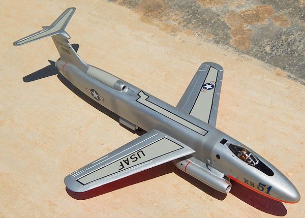
 When one
thinks of early jet bomber design, whether it is a US, Russian or British
make of all the designs that may come to mind, the XB-51 image will stand
out owing to its unique appearance. Two jet engines slung under the forward
fuselage and another embedded in the rear fuselage. From early years,
Hobby-Time served justice to a type ever neglected by injection moulding
manufacturers, when it released the scale model made in Balsa wood. The kit
comes with reasonably good scale plans and very accurate profile of the pre
marked wood parts.
When one
thinks of early jet bomber design, whether it is a US, Russian or British
make of all the designs that may come to mind, the XB-51 image will stand
out owing to its unique appearance. Two jet engines slung under the forward
fuselage and another embedded in the rear fuselage. From early years,
Hobby-Time served justice to a type ever neglected by injection moulding
manufacturers, when it released the scale model made in Balsa wood. The kit
comes with reasonably good scale plans and very accurate profile of the pre
marked wood parts.
Definitely this is not the type
of kit that one expects to select when buying a kit these days. A far cry
from the super detail injection moulded kits we find on the market nowadays.
For the past two years I have exhausted all my efforts to get an Execuform
vac form kit of which I came to know contained accurate scale plans.
Following the release of the Anigrand kit the production of this vac kit
came to an abrupt end. A resin kit is the last thing I will go for my next
option was to make a ‘Google search’ to see what was on offer and up came
the search with a Hobby-Time kit from Phil Juvet in the US. The kit was with
me within a week that I placed the order.
 The kit, which contained all the
wooden blanks, was still in its original cardboard box and the original
titles printed in red. Each blank was accurately outlined and easily snapped
so that one will only require to sand down the airfoil section using the
piece of sand paper that also comes with the kit. In a small sealed bag
there were the two sets of wheels black rubbery plastic and the cockpit
canopy that was clear injected plastic. The fuselage of the XB-51, which is
in the shape of a moray eel, is in the form of a wooden block that is cut in
outline but required sanding the round corners to shape. To simplify matters
the comprehensive instruction sheet gives accurate snap gauges that I copied
on a cardboard and cut shapes with scissors. These gauges at different
fuselage stations served to bring the correct fuselage airfoil. Balsa wood
blocks of different shape and sizes were to serve to shape all the kit
components.
The kit, which contained all the
wooden blanks, was still in its original cardboard box and the original
titles printed in red. Each blank was accurately outlined and easily snapped
so that one will only require to sand down the airfoil section using the
piece of sand paper that also comes with the kit. In a small sealed bag
there were the two sets of wheels black rubbery plastic and the cockpit
canopy that was clear injected plastic. The fuselage of the XB-51, which is
in the shape of a moray eel, is in the form of a wooden block that is cut in
outline but required sanding the round corners to shape. To simplify matters
the comprehensive instruction sheet gives accurate snap gauges that I copied
on a cardboard and cut shapes with scissors. These gauges at different
fuselage stations served to bring the correct fuselage airfoil. Balsa wood
blocks of different shape and sizes were to serve to shape all the kit
components.
| CONSTRUCTION |
All I have used from this kit is
basically the fuselage balsa block. The rest of the kit was scratch built
from scrap plastic pieces. A gig was also made in cardboard to use when the
wings dihedral are to fix at the correct angle. With the fuselage smoothened
to shape a coat of dope mixed with little talc powder was applied and this
was followed by sanding. The open grain pores were practically all closed
bringing a
 smooth surface finish throughout. The wheel wells were then
marked and curved out. The box like interior of each well was then covered
with a plastic card cut to fit forming smooth interior walls to which detail
was added at a later stage. The third engine space which is embedded at the
rear of fuselage was curved out forming a groove and a tube like engine was
embedded in it, fixing it in place and fairing smooth using filler to the
sides. The other two under fuselage engines were shaped from two belly tanks
that came from a Hasegawa Voodoo F-101 kit. These had the ends cut and
shaped by filing. A centre bullet shape was added inside the intake of all
three engines using rounded plastic sprue of correct diameter.
smooth surface finish throughout. The wheel wells were then
marked and curved out. The box like interior of each well was then covered
with a plastic card cut to fit forming smooth interior walls to which detail
was added at a later stage. The third engine space which is embedded at the
rear of fuselage was curved out forming a groove and a tube like engine was
embedded in it, fixing it in place and fairing smooth using filler to the
sides. The other two under fuselage engines were shaped from two belly tanks
that came from a Hasegawa Voodoo F-101 kit. These had the ends cut and
shaped by filing. A centre bullet shape was added inside the intake of all
three engines using rounded plastic sprue of correct diameter.
Wings, tail
planes, fin and rudder were made from scrap plastic correctly cut in outline
and then shaped to respective airfoil sections. I opted to use plastic for
all of these parts as it was easier to scrape panel lines and control
surfaces than using the wooden parts supplied. Six triangular shaped
brackets were then cut and fixed under each of the wing surfaces. These were
actuators. Wing tip dolly wheels were also made from scrap plastic and added
to the wing tips. A pylon was shaped from a thick plastic piece and fitted
to each engine pod. This had dowels at the joining end to secure each of the
engines to the fuselage.
 The cockpit was then cut out and
the pit itself smoothened as best one could. A plastic base plate was added
and on top were mounted the ejection seat, control wheel, rudder pedals,
instrument panel and side instrument. As for the radio operator compartment,
there is very little that could be seen from the starboard side window and
there was no scope to add any detail there. Even the round window itself was
represented by a circular black decal that had the same effect as seen in
photos.
The cockpit was then cut out and
the pit itself smoothened as best one could. A plastic base plate was added
and on top were mounted the ejection seat, control wheel, rudder pedals,
instrument panel and side instrument. As for the radio operator compartment,
there is very little that could be seen from the starboard side window and
there was no scope to add any detail there. Even the round window itself was
represented by a circular black decal that had the same effect as seen in
photos.
Main wings were superglue in
place guided by dowel pins that were carefully fitted to correspond with the
inclined wing root. The tail fin bullet shape at top was made from a small
fuel tank. A set of wheels of right size replaced the somewhat under scale
kit wheels adding a scratch built oleo legs complete with landing light and
other visible detail.
| COLORS & MARKINGS |
Cockpit interior painted
predominantly black with touches of white and silver for the instruments,
seat cushions were olive drab, a crew figure added and cockpit canopy fixed
in place with Klear{Future} and
 allowed to set. Wheel wells painted zinc
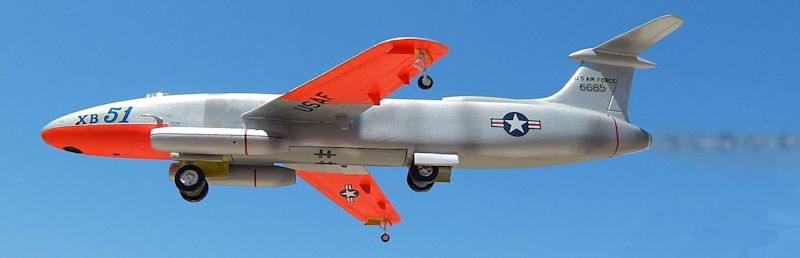
chromate green and wheel legs in silver. The nose legend XB-51 and the fin
serial number came from kit decals but other USAF legend were all scale
master decals picking the correct size as appropriate. The US insignia were
picked from Super Scale decal sheet.
allowed to set. Wheel wells painted zinc
chromate green and wheel legs in silver. The nose legend XB-51 and the fin
serial number came from kit decals but other USAF legend were all scale
master decals picking the correct size as appropriate. The US insignia were
picked from Super Scale decal sheet.
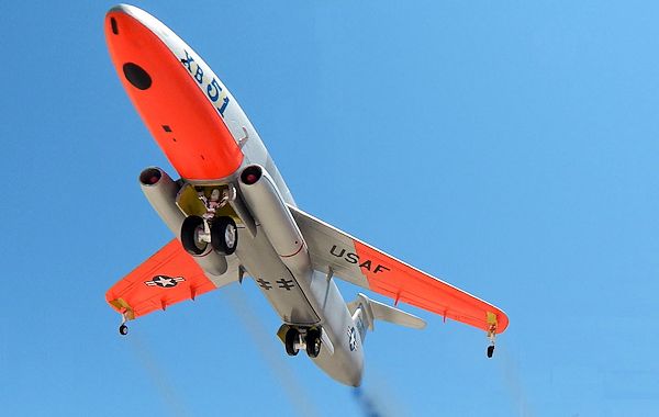
The XB-51was finished in Day Glow Model Master Blaze at the front lower fuselage and the outer half of the wing undersides. The rest of airframe was silver using Hempel paints thinned down for airbrush use. Finally kit was given a brush coat of Klear.
| CONCLUSIONS |
Building a model of the XB-51
brings back memories of a unique aircraft and of the colourful post war era
colorschemes on aircraft
that gave contribution towards the development of early
aircraft designs and systems .
| REFERENCES |
1] Wings of
fame
2] Hobby-Time
kit instructions
http://en.wikipedia.org
August 2013
If you would like your product reviewed fairly and fairly quickly, please contact the editor or see other details in the Note to Contributors.