Execuform 1/72 XP-87 Blackhawk
|
KIT #: |
? |
|
PRICE: |
Pretty sure it was under $10 at the
time. Ed |
|
DECALS: |
None |
|
REVIEWER: |
Carmel J. Attard |
|
NOTES: |
Bare bones vacuform kit with no external detail |
The XP-87 Blackhawk conceived in
response to USAF request for an all weather jet powered interceptor. Design
attempted to integrate radar, weapons, crew and aircraft into self contained,
ground vectored air defence weapon. It was the first pure jet aircraft and also
the last project made by Curtiss. Curtiss leader Walter Tydon designed this
radar equipped multi-jet night fighter. The type was powered by four engines
type Westinghouse J-34 WE7 each giving 2,795 lbs static thrust. It could attain
a maximum speed of 564 mph, a service ceiling of 45,000 ft and a range of 1,891
nautical miles with 3,100 gallons of fuel.
Development crippled due to early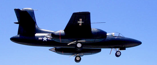 state of the art technical
inadequacies. This manifested that the interceptor had underpowered engines
overweight, dynamic flutter in empennage components, excessive take off run,
brake fade, and radar failures. Time, technology and politics were the cause for
this to be the last Curtiss design for the Air Force. The aircraft achieved 66
hours of flight time during 56 scheduled flight tests.
state of the art technical
inadequacies. This manifested that the interceptor had underpowered engines
overweight, dynamic flutter in empennage components, excessive take off run,
brake fade, and radar failures. Time, technology and politics were the cause for
this to be the last Curtiss design for the Air Force. The aircraft achieved 66
hours of flight time during 56 scheduled flight tests.
The main bulkheads at wing spars pass through, pressure cabin, empennage
and armament areas. Remaining sections joined by longeron and beltframes covered
with metal skins having flush access panels. The wing had dual main spars with
deep lip flanged machined skin panels inboard and tapered skins outboard.
All-metal aileron, speed brakes and wing flaps. Nacelle box shaped to house two
engines and main landing gear. The gear attaches from steeple frame from main
spars. Engine intake ducts divides
around wheel well. Tail cone divider is of stainless steel with removable
panels. Nose gear well is 9.5 inches offset to port of centre. The horizontal
tail has multiple spars with heavy tapered skins. Elevator is all metal and has
two mass balance configurations, which were used during the test program.
Vertical tail and dorsal had multiple closely spaced spars with heavy
skins. Rudder is all metal. Armament was not fitted on flight test aircraft.
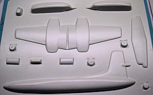
Kit is ‘bare bones’
not much detail at all. Every detail had to be scratch built, no interiors, no
landing gear oleo or wheel well detail or crew office interior at all. It
consists of two sheets of white styrene with vac-form parts to make all the
major components essential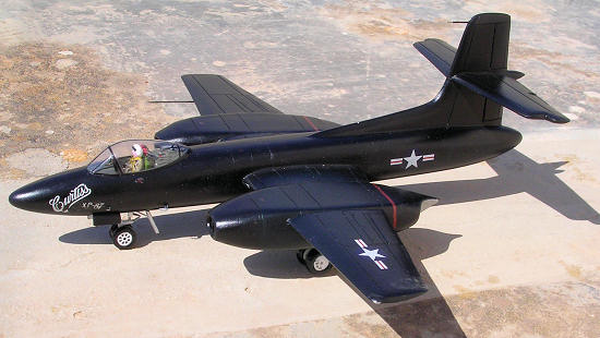 ly wing, tail planes and fuselage parts. Six bulkhead
sections are given on scale plans so that these can be made from backing
styrene. A canopy in clear acetate is also provided. There are two instruction
sheets. An A4 size sheet with building instructions and a double A4 size sheet
printed on blue paper which contains accurate 4-view 1/72 scale plans by Mike Herrill, which are excellent for reference purposes. A scrap view also shows the
position of the offset nose gear. 5 bulkhead sections are also depicted to
produce them from plastic sheet.
ly wing, tail planes and fuselage parts. Six bulkhead
sections are given on scale plans so that these can be made from backing
styrene. A canopy in clear acetate is also provided. There are two instruction
sheets. An A4 size sheet with building instructions and a double A4 size sheet
printed on blue paper which contains accurate 4-view 1/72 scale plans by Mike Herrill, which are excellent for reference purposes. A scrap view also shows the
position of the offset nose gear. 5 bulkhead sections are also depicted to
produce them from plastic sheet.
A quick observation
indicates that as with several of vac form models the vac parts have a slightly
blistered aspect at the surface which means that in order not to have part items
on the thick side there have to be scraping on the outer surface of parts before
one starts to draw and scribe the panel lines and other detail.
 The round part
edges are scribed, and then broken away from the sheet. The edges are sanded
on a flat sanding paper until a crisp seam line joint is produced, extra
care for trailing edges. Having obtained the desired shape of parts,
reference is made to drawing and panel lines and/or or brakes on all wings
and part of fuselage sections are all drawn in pencil. With each part placed
flat on a surface, a steel ruler and sharp pointed blade are used to score
to a certain depth on the marked panel lines. No special tool is used but
these same lines are scored aga
The round part
edges are scribed, and then broken away from the sheet. The edges are sanded
on a flat sanding paper until a crisp seam line joint is produced, extra
care for trailing edges. Having obtained the desired shape of parts,
reference is made to drawing and panel lines and/or or brakes on all wings
and part of fuselage sections are all drawn in pencil. With each part placed
flat on a surface, a steel ruler and sharp pointed blade are used to score
to a certain depth on the marked panel lines. No special tool is used but
these same lines are scored aga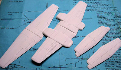 in this time using the blunt end of an X-acto
blade so that the ridges formed are removed. Fine sanding removes any
residue left. I found this technique quite effective in the end.
in this time using the blunt end of an X-acto
blade so that the ridges formed are removed. Fine sanding removes any
residue left. I found this technique quite effective in the end.
Bulkheads are made for
the fuselage and nacelles. A floor is installed at the cockpit and detail to
suite added to interior which are in form of instrument panel and bulkhead, side
consoles, two ejection seat and control column, as well as equipment that one
could imagine after reference to photo particularly the space at aft of crew
seats. A compartment inside the nose is built to house the lead weight, while
box shaped plastic blocks are built and
 fixed to the nose and engine nacelles to
form the wheel wells. A long wing spar is passed through cut square holes in the
fuselage halves.
fixed to the nose and engine nacelles to
form the wheel wells. A long wing spar is passed through cut square holes in the
fuselage halves.
With nacelle bulkheads
in place, the engine nacelle halves are dry fitted, and when desired correctness
is obtained the nacelle halves are fixed together. Each nacelle needed tail pipe
area opened up and two styrene tubes installed for exhaust tail pipes. The
nacelle nose cap required the addition of the intake duct. Halves. These ducts
had two vertical divider plates installed at a slight angle. When dry the
nacelle and nose cap are fitted to upper wing half, and the bottom wing half is
now fixed to the wi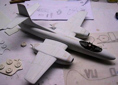 ng assembly. The wing spar is now positioned and bonded to
one side of the wing and nacelle parts so that the spar can slide through the
fuselage and provide extra strength. When the nacelle only are dry on one wing
half, the spar was slid through the fuselage and the opposite wing panels with
the vertical tail. When alignment is correct continued assembling the remaining
nacelle. For the tail planes a spar of aluminium tubing was installed through
the vertical fin. This aligned and bonded the two tail plane parts.
ng assembly. The wing spar is now positioned and bonded to
one side of the wing and nacelle parts so that the spar can slide through the
fuselage and provide extra strength. When the nacelle only are dry on one wing
half, the spar was slid through the fuselage and the opposite wing panels with
the vertical tail. When alignment is correct continued assembling the remaining
nacelle. For the tail planes a spar of aluminium tubing was installed through
the vertical fin. This aligned and bonded the two tail plane parts.
Attention was then
given to detailing the cockpit office, adding seats etc. Canopy was cut from
mold form and carefully trimmed to sit on fuselage contour. While adding the
little filler required care was taken not to fill the scribed detail panel
lines. The wheel well legs were made from metal tubing cut to small size and
joined to stretch sprue parts so that the scale plans were used for reference.
The wheels were slightly reduced in size while the nose wheels were replaced
with a set from spares box. These are smaller in diameter than the main wheels.
Wheel doors were detailed as best one could add detail to the inside face of
door parts. Scratch built segments formed brake pads that were added to main
wheel hubs.
Wheel wells were
zinc chromate but all door interiors were white. Cockpit interior is dark
grey while exhaust area being silver.
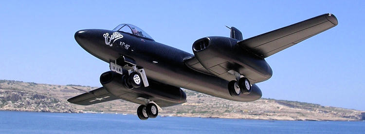
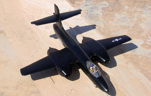 The rest of aircraft was overall high
gloss black, using Revell acrylic black, two coats with dry space in between
allowed. Other details as wheel legs and wheels were white and silver. I had
a decal sheet picked from spares box. Crew figure added to give scale
indication of the true size of the fighter aircraft. Window frames were made
from cut black decal strips and sealed in place with a coat of Klear.
The rest of aircraft was overall high
gloss black, using Revell acrylic black, two coats with dry space in between
allowed. Other details as wheel legs and wheels were white and silver. I had
a decal sheet picked from spares box. Crew figure added to give scale
indication of the true size of the fighter aircraft. Window frames were made
from cut black decal strips and sealed in place with a coat of Klear.
Like most of vac-form
kits this was fun to build and it also offered a challenge in a way as it
required a lot of additional parts, and more satisfying the result was. Thanks
to Scott Van Aken of
www.modelingmadness.com
who sent the kit for this
kit-build review. This also made me look deeper into what Execuform has on offer
in their vast range of kits. In due course more from this range will be
hopefully added to my future builds. In a few words, one tends to develop a
passion for vac form models and an obsession to build them.
Carmel J. Attard
June 2011If you would like your product reviewed fairly and fairly quickly, please contact the editor or see other details in the
Note to
Contributors.
Back to the Main Page
Back to the Review
Index Page