| KIT #: | 4800 |
| PRICE: | $46.00 |
| DECALS: | Three options |
| REVIEWER: | John Summerford |
| NOTES: |
| HISTORY |
Excerpted from Wikipedia.
 The Firebee I was the result of a 1948 U.S. Air Force request and
contract to Ryan for a jet-powered gunnery target. The first flight of the
XQ-2 Firebee prototype took place in early 1951. The drone featured swept
flight surfaces and a circular nose inlet. The initial models had
distinctive "arrowhead" shaped endplates on the tailplane. The Firebee could
be air-launched from a specially modified launch aircraft (Douglas A-26
Invader was first to be used for this), or ground-launched with a single
RATO booster.
The Firebee I was the result of a 1948 U.S. Air Force request and
contract to Ryan for a jet-powered gunnery target. The first flight of the
XQ-2 Firebee prototype took place in early 1951. The drone featured swept
flight surfaces and a circular nose inlet. The initial models had
distinctive "arrowhead" shaped endplates on the tailplane. The Firebee could
be air-launched from a specially modified launch aircraft (Douglas A-26
Invader was first to be used for this), or ground-launched with a single
RATO booster.
The Firebee was ordered into production for the USAF as the Q-2A, powered by a Continental J69-T-19B turbojet engine with 1,060 pounds-force (4.7 kN) of thrust. The Air Force then obtained small numbers of a Q-2B with a more powerful engine for high-altitude performance.
The U.S. Navy bought the Firebee as the KDA-1 which was mostly similar to the Q-2A, differing mainly in its powerplant: a Fairchild J44-R-20B turbojet with 1,000 lbf (4.4 kN) thrust. The KDA-1 and Q-2A could be distinguished by the KDA-1's protruding inlet center body and wider, steeply raked inlet. The U.S. Army also obtained a KDA-1 version designated the XM21 that differed only in minor details.
| THE KIT |
 A flimsy card stock lid covers a much
sturdier corrugated box. Inside that box one finds a resealable bag holding
two light gray sprues, an instruction sheet and decals. The larger sprue has
the parts for the Firebee and the smaller sprue the trailer. Not
surprisingly, there are no clear or photo-etch parts. Neither are there any
mold seams to clean up or flash to deal with.
A flimsy card stock lid covers a much
sturdier corrugated box. Inside that box one finds a resealable bag holding
two light gray sprues, an instruction sheet and decals. The larger sprue has
the parts for the Firebee and the smaller sprue the trailer. Not
surprisingly, there are no clear or photo-etch parts. Neither are there any
mold seams to clean up or flash to deal with.
Assembly instructions are printed on the metric equivalent of 11 by17 sheet with a brief history in Cyrillic and English plus a color chart referencing Revell and Tamiya paints and painting and decaling options on one side. Printed on the other side, are a parts map and 19 assembly steps. Total parts count is 34, but four are not used in this model
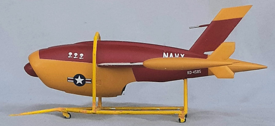
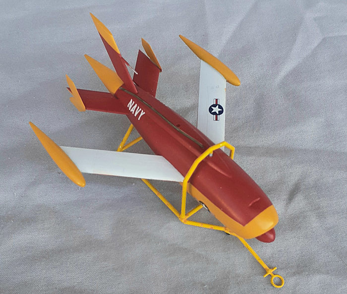
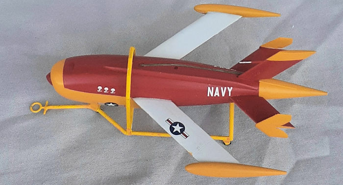
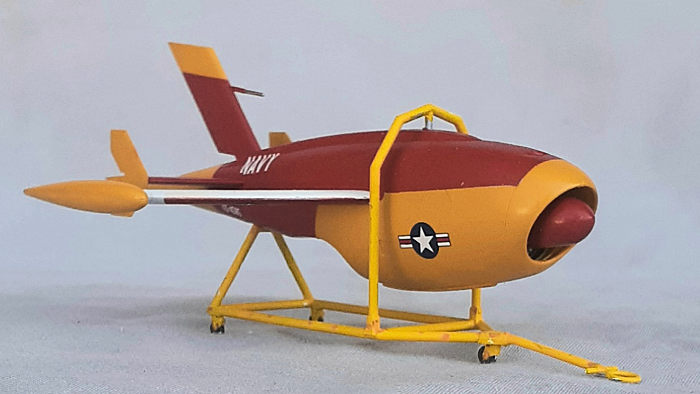
Decal options are for an Air Force all red airframe with white tip tanks, a Navy red and yellow airframe flown at China Lake Naval Test Station, the third being the mostly red -2 prototype with a shark mouth and eyes and is illustrated on the lid. (The second option includes a decal of three parachute stencils, which leads me to believe it survived three missions.)
| CONSTRUCTION |
Assembly begins with the engine turbine blades because, hey, there’s no cockpit to start on first. The first stage of the compressor section and intake trunking are assembled and installed and the fuselage is closed up in step 8. Wings and stabilizes come next. They are cleverly engineered so that they can be glued from the inside, eliminating any gaps. The top of the fuselage and tip tanks come next. Fin and stab finlets finish the drone’s assembly in step 16. The next two steps regard the trailer and the final step brings the two together.
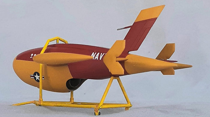
| COLORS & MARKINGS |
 Of course, It’s not quite that simple.
I opted to pre-paint the intake area and mask it for seam clean-up when the
halves are joined. A touch-up coat of yellow went over the seam. The paint
scheme I chose is for the Firebee used by the Navy at China Lake, which is
just over a one-hour drive north of Edwards AFB.
Of course, It’s not quite that simple.
I opted to pre-paint the intake area and mask it for seam clean-up when the
halves are joined. A touch-up coat of yellow went over the seam. The paint
scheme I chose is for the Firebee used by the Navy at China Lake, which is
just over a one-hour drive north of Edwards AFB.
A coat of tan primer was sprayed on in preparation for the paint. I knew that masking for each of the four colors would be time consuming, but I didn’t expect to spend over 10 hours doing it. It didn’t help that I had to do touch-ups for each color.
Two coats of gloss overcoat got the model ready for decaling. The decals are thin, difficult to maneuverer in place and easy to fold onto themselves when sliding off of the backing paper. Their color density is very good. A coat of satin finish toned the gloss down and sealed the decals.
| CONSTRUCTION CONTINUES |
 Before removing the lower frame plus
tow bar piece of the trailer from the sprue, the wheels were glued in place.
Despite being very careful removing the frame, the tow bar broke. This
created an opportunity to correct a problem. The tow bar is molded in the
same plane as the frame, meaning that the tow ring hovers above the
pavement. A new tow bar was cut to length from some rod stock and the
handle/ring glued on one end. While that was curing, a small jig was cut
from basswood stock to prop up the other end of the tow bar and attach to
the frame in a drooped position. The joints were reinforced with some cyano.
The upper trailer pieces easily fit in place.
Before removing the lower frame plus
tow bar piece of the trailer from the sprue, the wheels were glued in place.
Despite being very careful removing the frame, the tow bar broke. This
created an opportunity to correct a problem. The tow bar is molded in the
same plane as the frame, meaning that the tow ring hovers above the
pavement. A new tow bar was cut to length from some rod stock and the
handle/ring glued on one end. While that was curing, a small jig was cut
from basswood stock to prop up the other end of the tow bar and attach to
the frame in a drooped position. The joints were reinforced with some cyano.
The upper trailer pieces easily fit in place.
This time a coat of white rattle can primer was sprayed on the trailer. A brown felt tip marker was swiped around the joints and random areas to act as some pre-shading weathering. A couple coats of a lighter shade of yellow was brushed on., then the wheels painted.
Mounting the Firebee to the trailer takes some dexterity. I applied small drops of glue in the recesses and then held both vertically while the glue took hold.
| CONCLUSIONS |
Fit of the parts is very good, making assembly incredibly easy. I spent less than seven hours putting it together which means that most of the time was spent masking, painting and decaling. The other options are much simpler to paint. The trailer is nice addition, making it easier to display the Firebee. Now about that A-26 kit with two drones slung under the wings?
J
anuary 2022
Copyright ModelingMadness.com. All rights reserved. No
reproduction in part or in whole without express permission.
If you would like your product reviewed fairly and fairly quickly, please
contact the editor or see other details in the
Note to
Contributors.